
95% of researchers rate our articles as excellent or good
Learn more about the work of our research integrity team to safeguard the quality of each article we publish.
Find out more
ORIGINAL RESEARCH article
Front. Phys. , 29 September 2022
Sec. Optics and Photonics
Volume 10 - 2022 | https://doi.org/10.3389/fphy.2022.1012470
This article is part of the Research Topic Transformation Optics and its Frontier Branches View all 11 articles
Transformed Luneburg lens has been widely employed to provide aberration-free imaging and high-gain antenna system, but whose focal plane and beam scanning range decrease correspondingly. In this paper, a two-dimensional compressed elliptical cylindrical Luneburg lens is presented based on transformation optics (TO) to achieve miniaturization and wide-angle beam steering. The Jacobian matrix and the permittivity tensor are calculated after supposing formulas to compress the focal plane, while maintaining the lens’ inherent performance. The gradient permittivity is achieved by two ring-type periodic unit cells on the basis of the Equivalent Medium Theory. The lens is then attached between a pair of parallel metal plates to further improve its gain and lower the side lobe level (SLL). To demonstrate this assumption, a prototype of this Luneburg lens is manufactured by isotropic material and 3D printing technique. The antenna operates at 3.3–5 GHz with a peak gain of 16.1/15.9 dBi. A 2D beam scanning range of ±50° and ± 20° can be implemented by merely five feeds, the side lobe level keeping less than -16.3/-16 dB. Measured results coincide well with theoretical predictions, offering a beneficial transformation mapping to both microwaves and optics.
Lens antenna system, a classic example of aperture array antennas, has the ability to regulate the propagation of electromagnetic waves from the perspective of the electromagnetic field. A typical representative is the Luneburg lens system. The Luneburg lens is originally an inhomogeneous dielectric spherical lens with a continuous refractive index [1], which is capable of converting the spherical wavefront into a planar wavefront and is widely applied in multi-beam and high gain scenario [2]; [3]; [4]. Despite the advantage of beam coherence, the sphere with large scale limits its wider application. With the advent of transformation optics (TO) [5]; [6] and quasi-conformal transformation optics (QCTO) [7], a Luneburg lens can be transformed to a lower and more conformal profile for the sake of better matching with feeds, while original performances of the lens are practically reserved.
Recently, profile reduction and miniaturization of the Luneburg lens have been widely investigated, the typical cases of which are truncated lens [8]; [9]; [10]; [11], hemispherical lens [12]; [13], ellipsoidal lens [14,15], discus lens [16,17]; [18], diffuse lens [19] and flat lens [20]; [21]; [22,23]; [24]; [25]; [26]. The key of all the aforementioned miniaturization is to assign new formulas to a particular coordinate or a group of boundary conditions of the sphere in one specific plane, and then apply it to lower the profile and propose a transformed lens. However, the beam scanning range and aperture efficiency would be lowered owing to the focal plane of the lens being minished. In order to radiate a wider scanning coverage and accommodate more feeds, [11] enlarged the focus surface to be extend-flattened based on QCTO. [14] proposed an lens array composed of two ellipsoidal Luneburg lenses, simultaneously enhancing its aperture efficiency and reducing the amount of feeds by introducing the local-beam shifting method. Alternatively, [26] increased its scanning angle via a transmission line made of two metallic surfaces, which can be regarded as a parallel-plate waveguide. In addition, the fabrication process of transformed Luneburg lens is fairly complicated due to the employment of multiple dielectric materials [16,17]; [18]; [20]; [25] or metamaterials [8]; [9]; [13]; [15]; [22,23]; [24].
This paper argues that the effective aperture of the lens can be adjusted while maintaining a wide scanning angle and high aperture efficiency. This is possible by simultaneously changing two coordinates. In this paper, an elliptical cylindrical Luneburg lens is proposed based on the transformation mapping, which is a novel scheme for miniaturization. The spherical Luneburg lens is transformed from two orthogonal directions, and the continuously spatially variable permittivity is then determined, approximated, discretized, and optimized. Additionally, one single material can be set with specified permittivity and implemented by 3D printing based on the Equivalent Medium Theory. Two ring-type periodic unit cells composed of photosensitive resin are created in order to obtain the gradient permittivity. Experiments reveal that the proposed lens for antenna applications can achieve an impedance bandwidth of 41% (3.3–5 GHz), a peak gain of 16.1/15.9 dBi, and a beam coverage of 100° in the H-plane and 40° in the E-plane with five feed antennas, with beam steering performance of ± 50° with only 1.2 dBi reduction in peak gain.
Figure 1A illustrates the novel scheme of bi-dimensional transformation. Set coordinates for a spherical lens are (x, y, z) in the virtual space, while those for an elliptical cylindrical lens are (x’, y’, z’) in the physical space. Suppose the spherical has a radius of R, the compression factor for the y-coordinate is δ, and it for the z-coordinate is η. Both δ and η take any real number between 0 and 1.
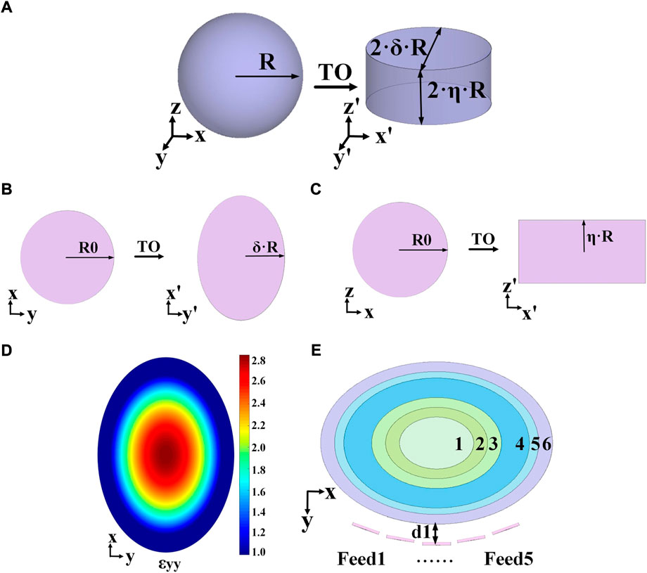
FIGURE 1. Transformation schematic of the Luneburg lens. (A) The proposed approach of transformation. (B) Compression of the y-coordinate. (C) Compression of the z-coordinate. (D) Distribution of the ɛyy component. (E) Shells and feeds.
In the transformation, the y-coordinate transformation is introduced to directly reduce the curvature of the lens profile and change the circular arc into an elliptical arc. And the z-coordinate transformation is proposed to change the original circular surface which is not easily conformable into a rectangle with straight upper and lower boundaries. The transformations of the y- and z-coordinate are all compressed, while the transformation of the x-coordinate are essentially expanded, so that the long axis of the ellipse can be controlled to be R.
A spherical lens can be regarded as an infinite number of planar circles, where the radius of each circle is a function of the coordinates of a point on the circumference as the independent variable. Take a point (x0,y0,z0) as an example. Let the radius of its circle be R0, as shown in Figures 1B,C.
Through coordinate transformation, the circle can be changed into an ellipse with long axis 2R and short axis 2ηR in the H- plane, as illustrated in Figure 1B. And Figure 1C shows that this circle is changed to be a rectangle with length 2R and width 2δR in its orthogonal E- plane. The transformations are namely two-dimensional compression.
The equation of the permittivity of the spherical lens is:
The transformation formulas can be defined as:
For singularities in Formula 2, note x’ = x = 0 in the case of z = ±R, and z’ = z = 0 in the case of y = ±R. In the subsequent analysis, the effect of the 4 singularities is neglected. The Jacobian transformation matrix, the permittivity tensor and the permeability tensor are calculated in the following equations:
where
According to Formulas 4, 5, the elliptical Luneburg lens’ constitutive parameters possess significant anisotropy on account of non-diagonal tensor components. As a result, the permittivity tensor’s numerical value should be processed before being applied to next step.
Most researchers are inclined to deal with the permittivity tensor firstly, and then fabricate Luneburg lens with isotropic materials. There are four representative methods. Method 1: Change the non-diagonal tensor to be a diagonal one by eigenvalues, and then set components of the tensor which are less than one [20] or insensitive to the lens performance to be one [13]. Method 2: For the diagonal tensor, calculate the plane wave dispersion equation and determine a component with the greatest value in the tensor as the permittivity value [14]. Method 3: Designate a component in the diagonal tensor that most affects the lens performance and then directly assume and approximate the numerical value of the permittivity [15]; [16,17]; [18]; [19]; [22,23]. Method 4: Directly rotate the transformed coordinate system x’y’z’ by an angle ϕ, then adjust ϕ to make the non-diagonal elements in the tensor become 0. The element with the greatest influence on wave propagation is specified to be the permittivity value [21]; [27].
Firstly, in order to fully utilize the lens’s focusing capabilities, the xoz plane with the largest section area is chosen as the focal plane. The electromagnetic waves radiated from the feed will be nearly perpendicular to the xoz plane and relatively parallel to the y-axis direction. As a result, the ɛyy component of
Define R = 100 mm, δ = 0.7, and η = 0.5. This compression reduces the size of the lens from 4πR3/3 to 2πηδR3, a volumetric reduction of 47.5%. Meanwhile, the focal plane (the xoz plane) is reduced from πR2 to 4ηR2, an areal reduction of 36.3%. Obviously, the focal plane realizes a relative expansion in comparison with the volume, promising a broader steering angle. Furthermore, the curvature of the lens becomes smaller (from 1/R to δ/R), which is favorable for matching with more feed sources. Figure 1D is the numerical distribution of ɛyy calculated in MATLAB, varying from 1 to 2.86. The gradient permittivity and the size of each layer are listed in Figure 1E; Table 1 in accordance with the gain optimization approach of multishell Luneburg lenses in [28]. The variables lx and ly respectively denote the long and short axes of the elliptical cylinder.
Periodic unit cells are often employed to actualize the gradient permittivity distribution of Luneburg lens, and the common forms include the ring-type units [3], the cubical lattices [4,8], and the hole-type units [29]. Compared with other unit cells, the ring-type units are less sensitive to the angle of incidence and more conducive to beam consistency, hence being employed to realize gradient permittivity. The design of ring-type units is on the basis of the A-BG formula of the Equivalent Medium Theory [30], which actually involves mixing dielectric materials within a cell to obtain equivalent electromagnetic properties. It is widely used in the design of the aforementioned periodic unit cells. The formula is as follows:
The equivalent permittivity of the cell ɛeff can be calculated based on the permittivity of the substrate material ɛh, the permittivity of the insert material ɛi and the volume fraction of the insert material to the whole p. From the perspective of easy preparation, the substrate material is photosensitive resin (ɛr = 2.85, tanδ = 0.005), a common material for 3D printing technology. Furthermore, the photosensitive resin material is stable, which means its refractive index and permittivity slightly vary with the frequency increasing. It hardly affects the performance of the antenna. The insert material is air (ɛr = 1, tanδ = 0). Relative permittivity of Shell 1 can be directly attained by resin, and that of Shells 2–6 can be attained by resin with periodic unit cells, which are shown in Figures 2A,B with b = 7 mm, w = 8 mm and h = 10 mm. White for air, blue for photosensitive resin. The volume fraction p in the ring-unit with different inclusions is in the following equation:
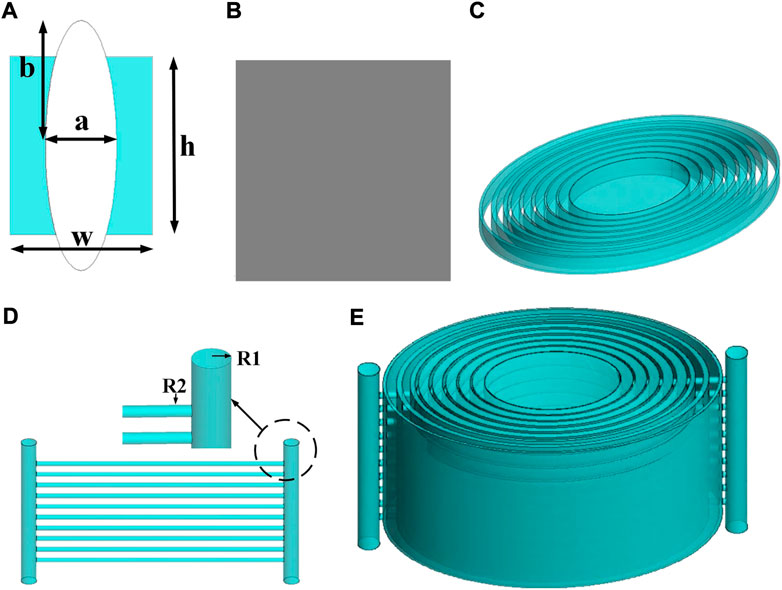
FIGURE 2. Schematic of the proposed Luneburg lens. (A) The ellipse ring-type unit. (B) The rectangle ring-type unit. (C) The single layer lens composed of periodic unit cells. (D) The supporting frame. (E) The elliptical Luneburg lens.
Values of a and permittivity are calculated based on Formulas 6, 7, as listed in Table 2. The combination schematic of the two periodic unit cells is in Figure 2C. To ensure the robustness of the lens, a support structure is introduced. The support structure of the lens is also made of photosensitive resin with two vertical cylinders of radius R1 = 6.5 mm and 10 horizontal cylinders of radius R2 = 2 mm, as illustrated in Figure 2D. The assembled elliptical lens is in Figure 2E.
The feed antenna is a dual-polarized dipole antenna, consisting of two orthogonal modified bowtie dipoles, parasitic elements and a cavity [31]. Parameters of the antenna is modified to operate at 3.3–5 GHz. The simulations are performed in Altair FEKO (2021.2), and the gain, S11, S22, S21 of the feed are shown in Figure 3.
The gain of the proposed lens antenna is optimized below. According to [24], transformation mapping would cause the focal point’s initial placement on the lens’ surface to move to the exterior of the lens. As a result, the optimal distance between the feed source and the lens needs to be investigated. The feed antenna is positioned at four distinct points during simulations, with d1 standing for the distance between the feed and the lens surface. Results are summarized in Figures 4A,B. It is obvious that the gain is prime at d1 = 0.2λ for 14.5/14.3 dBi. The antenna is fixed between two parallel metal plates in order to further improve gain and decrease side lobe level [26]; [32]. Figure 4C depicts two plate shapes, both of which are 1.5 mm thick. Gain curves for the lens antenna are shown in Figures 4D,E, where d2 denotes the separation between the plates and the lens. With Plate 2 and d2 = 10mm, it is discovered that the gain reaches its maximum of 16.9/16.8dBi.
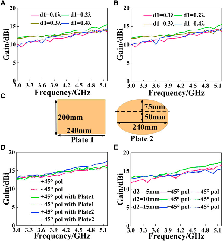
FIGURE 4. Gain performance of the proposed Luneburg lens antenna. (A) Gain for +45° pol with different d1. (B) Gain for -45° pol with different d1. (C) Two type of plates. (D) Gain with two plates. (E) Gain with different d2.
Further investigation into multi-beam properties of the proposed lens is operated. Only results of +45° polarization are shown for simplicity. Figure 5 contrasts the normalized electric field distribution, where the five subjacent plots are under the circumstance of beams passing through the proposed lens. As can be observed from Figure 5, the relative phase of the propagating fields is rebuilt and then the necessary wave-transformation functions to enhance gain and turn the original spherical wavefront to be planar, conforming to the inherent characteristics of Luneburg lens. Figure 6 depicts radiation patterns in the E- and H-plane at 3.3 GHz. It can be seen from the pattern that the cross-polarization level of multiple beams is higher than 18.5dB, and the SLL is lower than -19 dB. Since the beamwidth in H-plane is smaller than it in E-plane, multiple feeds must be put in H-plane, so as to achieve a wide beam coverage. The beamwidth is the sole factor that is affected by the differing lens diameters in the E- and H-plane, while dual-linear polarization remain unchanged.
The feed antenna is depicted in Figure 7A. The proposed elliptical cylindrical Luneburg lens in Figures 7B,C is fabricated by Stereo Lithography Apparatus, a technique of 3D printing. Figure 8A is the measured result, indicating S-parameters of the feed. In 3.3–5 GHz, S11 is less than -10 dB and S21 is less than -30 dB, hence the impedance bandwidth reaches up to 41%. The measured result coincides well with its simulation. Both processing accuracy and measurement error contribute to the slight performance degradation. Contrast of gain curves are shown in Figure 8B, with the maximum value of 16.1/15.9 Bi. Electromagnetic beams radiated from the feed antennas are focused by the transformed lens, thus greatly narrowing beams and enhancing the gain. As can be seen in Figure 8B, gain curves with lens are not consistent, which is common for transformed lenses. Because the transformation mapping applied in this letter is longitudinally parallel to the y- and z-direction, instead of radial mapping, which changes the original radial refractive index distribution and intrinsical rotational symmetry of the spherical lens. Besides, the placement of feed antennas in Figure 1A can also produce different convergences of beams, inevitably resulting in slight diversities and degradation in the final gain. Figure 9 is the measured normalized electric field distribution, which coincides with the simulated results. The different half power bandwidths (HPBW) in Figure 10 strongly prove that the elliptic cylindrical lens can not only independently control the beam in different planes, but also assure its multi-beam performance. And the wider beamwidths in the E-plane can reduce the number of feeds in the same plane. Dual-polarization is achieved by the dipole feed antenna, with cross-polarization level of 17/16.8 dB and the SLL of -16.3/-16 dB.
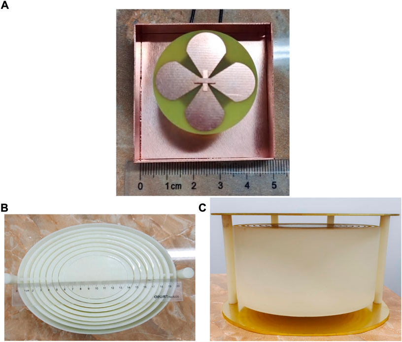
FIGURE 7. The elliptical cylindrical Luneburg lens. (A) The feed antenna. (B) The 3-D printed lens. (C) The overall structure.
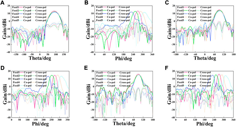
FIGURE 10. Measured radiation patterns for +45° pol. (A) E-plane at 3.3 GHz. (B) H-plane at 3.3 GHz. (C) E-plane at 4.2 GHz. (D) H-plane at 4.2 GHz. (E) E-plane at 5.0 GHz. (F) H-plane at 5.0 GHz.
A comparison between the proposed Luneburg lens and other reported Luneburg lenses based on TO is summarized in Table 3. After the compression in the y-dimension and z-dimension, the antenna has a more miniaturized scale than other lenses that are merely transformed in one dimension. In addition, the flat structure of the elliptical cylinder makes it more conformal and allows for a wider range of practical applications. The proposed two-dimensional coordinate transformation compresses the geometry of the Luneburg lens, making its electrical size is smaller than that in [13, 18]. And the gain of the proposed antenna is superior to antennas in [13, 23]. The different beamwidths in the E- and H-plane enable the proposed antenna to achieve two-dimensional beam coverage with five feed antennas, and produce a wider beam coverage than that in [15, 18].
Based on the analysis of transformed lenses in antenna applications, this paper presents a novel bi-dimensional transformation mapping to minimize the geometry of Lunebueg lens. Through compression, the lens changes from a sphere to an elliptical cylinder, reducing its volume by 47.5%. Meanwhile, since the vertical section of the lens in the xoz plane has the largest profile, it is identified as the focal plane. It contributes to matching with more feeds and steering in a wide angle. Both transformed permittivity tensor and permeability tensor are anisotropic, and they are modified to be isotropic following approximation and discretization. In order to implement the inhomogeneous lens, two ting-type periodic unit cells are designed to achieve the presumptive permittivity. The gain can be further improved through the gain optimization method and a pair of parallel metal elliptical plate, eventually reaching up to 16.1/15.9 dBi. The elliptical cylindrical Luneburg lens is fabricated with photosensitive resin. By reasonably adjusting the position of feed antennas, merely five beams can achieve a two-dimensional beam coverage of 100° in the H-plane and 40° in the E-plane.
The original contributions presented in the study are included in the article/supplementary material, further inquiries can be directed to the corresponding author.
YZ designed the structure and then performed the experiments. The final manuscript was written by YZ and YZ. The numerical calculation was finished by WX and LB. YY and XL fabricated the sample. All authors contributed to the manuscript.
National Natural Science foundation of China (61771490), the Natural Science Foundation of Shaanxi Province, China (2018JM6055), Basic research Foundation of Engineering University of PAP (WJY201908) and Excellent Postgraduate Training Program of Engineering University of PAP (XYYJS01).
The authors declare that the research was conducted in the absence of any commercial or financial relationships that could be construed as a potential conflict of interest.
All claims expressed in this article are solely those of the authors and do not necessarily represent those of their affiliated organizations, or those of the publisher, the editors and the reviewers. Any product that may be evaluated in this article, or claim that may be made by its manufacturer, is not guaranteed or endorsed by the publisher.
2. Liu K, Zhao C, Qu S-W, Chen Y, Hu J, Yang S. A 3-d-printed multibeam spherical lens antenna with ultrawide-angle coverage. IEEE Antennas Wirel Propag Lett (2021) 20:411–5. doi:10.1109/LAWP.2021.3054042
3. Li Y, Ge L, Chen M, Zhang Z, Li Z, Wang J. Multibeam 3-d-printed luneburg lens fed by magnetoelectric dipole antennas for millimeter-wave mimo applications. IEEE Trans Antennas Propag (2019) 67:2923–33. doi:10.1109/TAP.2019.2899013
4. Guo Y, Li Y, Wang J, Ge L, Zhang Z, Chen M, et al. .A 3d printed nearly isotropic luneburg lens antenna for millimeter-wave vehicular networks. IEEE Trans Veh Technol (2022) 71:1145–55. doi:10.1109/TVT.2021.3134703
5. Pendry JB, Schurig D, Smith DR. Controlling electromagnetic fields. science (2006) 312:1780–2. doi:10.1126/science.1125907
7. Li J, Pendry JB. Hiding under the carpet: A new strategy for cloaking. Phys Rev Lett (2008) 101:203901. doi:10.1103/physrevlett.101.203901
8. Ma HF, Cui TJ. Three-dimensional broadband and broad-angle transformation-optics lens. Nat Commun (2010) 1:124–7. doi:10.1038/ncomms1126
9. Biswas S, Mirotznik M. High gain, wide-angle qcto-enabled modified luneburg lens antenna with broadband anti-reflective layer. Sci Rep (2020) 10:12646–13. doi:10.1038/s41598-020-69631-6
10. Driscoll T, Lipworth G, Hunt J, Landy N, Kundtz N, Basov DN, et al. Performance of a three dimensional transformation-optical-flattened lüneburg lens. Opt Express (2012) 20:13262–73. doi:10.1364/oe.20.013262
11. Li Y, Zhu Q. Luneburg lens with extended flat focal surface for electronic scan applications. Opt Express (2016) 24:7201–11. doi:10.1364/oe.24.007201
12. Weily AR, Nikolic N. Dual-polarized planar feed for low-profile hemispherical luneburg lens antennas. IEEE Trans Antennas Propag (2011) 60:402–7. doi:10.1109/tap.2011.2167941
13. Xu R, Chen ZN. A hemispherical wide-angle beamsteering near-surface focal-plane metamaterial luneburg lens antenna using transformation-optics. IEEE Trans Antennas Propag (2022) 70:4224–33. doi:10.1109/tap.2021.3138554
14. Wang B, Wang C, Zhu Q. An ellipsoidal luneburg lens antenna for gain enhancement and beam scanning. 2021 7th International Conference on Computer and Communications (ICCC). IEEE (2021). 10-13 December 2021. Chengdu, China p. 2149–53.
15. Wang C, Xia Y, Guo G, Nasir M, Zhu Q. Ellipsoidal luneburg lens binary array for wide-angle scanning. IEEE Trans Antennas Propag (2020) 68:5702–7. doi:10.1109/tap.2020.2969875
16. Demetriadou A, Hao Y. Slim luneburg lens for antenna applications. Opt Express (2011) 19:19925. doi:10.1364/oe.19.019925
17. Demetriadou A, Hao Y. A grounded slim luneburg lens antenna based on transformation electromagnetics. IEEE Antennas Wirel Propag Lett (2011) 10:1590–3. doi:10.1109/lawp.2011.2180884
18. Giddens H, Andy AS, Hao Y. Multimaterial 3-d printed compressed luneburg lens for mm-wave beam steering. IEEE Antennas Wirel Propag Lett (2021) 20:2166–70. doi:10.1109/lawp.2021.3109591
19. Quevedo-Teruel O, Hao Y. Directive radiation from a diffuse luneburg lens. Opt Lett (2013) 38:392–4. doi:10.1364/ol.38.000392
20. Mateo-Segura C, Dyke A, Dyke H, Haq S, Hao Y. Flat luneburg lens via transformation optics for directive antenna applications. IEEE Trans Antennas Propag (2014) 62:1945–53. doi:10.1109/tap.2014.2302004
21. Guo G, Nasir M, Zhu Q. Subtracted flat generalized luneburg lens for high gain and low profile applications. 2019 IEEE 5th International Conference on Computer and Communications (ICCC) (IEEE) (2019). 06-09 December 2019. Chengdu, China p. 685–9.
22. Su Y, Chen ZN. A flat dual-polarized transformation-optics beamscanning luneburg lens antenna using pcb-stacked gradient index metamaterials. IEEE Trans Antennas Propag (2018) 66:5088–97. doi:10.1109/tap.2018.2858209
23. Su Y, Chen ZN. A radial transformation-optics mapping for flat ultra-wide-angle dual-polarized stacked grin mtm luneburg lens antenna. IEEE Trans Antennas Propag (2019) 67:2961–70. doi:10.1109/tap.2019.2900346
24. Xu R, Chen ZN. A transformation-optics-based flat metamaterial luneburg lens antenna with zero focal length. IEEE Trans Antennas Propag (2022) 70:3287–96. doi:10.1109/tap.2021.3137528
25. Kundtz N, Smith DR. Extreme-angle broadband metamaterial lens. Nat Mater (2010) 9:129–32. doi:10.1038/nmat2610
26. Marin JG, Hesselbarth J. Lens antenna with planar focal surface for wide-angle beam-steering application. IEEE Trans Antennas Propag (2019) 67:2757–62. doi:10.1109/tap.2019.2894336
27. Schurig D. An aberration-free lens with zero f-number. New J Phys (2008) 10:115034. doi:10.1088/1367-2630/10/11/115034
28. Fuchs B, Le Coq L, Lafond O, Rondineau S, Himdi M. Design optimization of multishell luneburg lenses. IEEE Trans Antennas Propag (2007) 55:283–9. doi:10.1109/tap.2006.889849
29. Ansari M, Jones B, Zhu H, Shariati N, Guo YJ. A highly efficient spherical luneburg lens for low microwave frequencies realized with a metal-based artificial medium. IEEE Trans Antennas Propag (2020) 69:3758–70. doi:10.1109/tap.2020.3044638
30. Merrill WM, Diaz RE, LoRe MM, Squires MC, Alexopoulos NG. Effective medium theories for artificial materials composed of multiple sizes of spherical inclusions in a host continuum. IEEE Trans Antennas Propag (1999) 47:142–8. doi:10.1109/8.753004
31. Yang Z, Zhang C, Yin Y-Z, Wang Y. A wideband dual-polarized modified bowtie antenna for 2g/3g/lte base-station applications. PIER Lett (2016) 61:131–7. doi:10.2528/pierl16052504
Keywords: transformation optics, Luneburg lens, lens antenna, multi-beam antenna, gradient index lenses
Citation: Zang Y, Zhu Y, Xie W, Yang Y, Bu L and Liu X (2022) A bi-dimensional compressed Luneburg lens antenna for miniaturization based on transformation optics. Front. Phys. 10:1012470. doi: 10.3389/fphy.2022.1012470
Received: 05 August 2022; Accepted: 12 September 2022;
Published: 29 September 2022.
Edited by:
Ben-Xin Wang, Jiangnan University, ChinaCopyright © 2022 Zang, Zhu, Xie, Yang, Bu and Liu. This is an open-access article distributed under the terms of the Creative Commons Attribution License (CC BY). The use, distribution or reproduction in other forums is permitted, provided the original author(s) and the copyright owner(s) are credited and that the original publication in this journal is cited, in accordance with accepted academic practice. No use, distribution or reproduction is permitted which does not comply with these terms.
*Correspondence: Yongzhong Zhu, YnNiczE5ODBAc2luYS5jb20=
Disclaimer: All claims expressed in this article are solely those of the authors and do not necessarily represent those of their affiliated organizations, or those of the publisher, the editors and the reviewers. Any product that may be evaluated in this article or claim that may be made by its manufacturer is not guaranteed or endorsed by the publisher.
Research integrity at Frontiers

Learn more about the work of our research integrity team to safeguard the quality of each article we publish.