 Francesco Taccogna
 Filippo Cichocki
 Pierpaolo Minelli
95% of researchers rate our articles as excellent or good
Learn more about the work of our research integrity team to safeguard the quality of each article we publish.
Find out more
ORIGINAL RESEARCH article
Front. Phys. , 19 October 2022
Sec. Low-Temperature Plasma Physics
Volume 10 - 2022 | https://doi.org/10.3389/fphy.2022.1006994
This article is part of the Research Topic Numerical Simulations of Plasma Thrusters and/or Related Technologies View all 8 articles
This work represents a first attempt to include the complex variety of electron-molecule processes in a full kinetic particle-in-cell/test particle Monte Carlo model for the plasma and neutral gas phase in a Hall thruster. Particular emphasis has been placed on Earth’s atmosphere species for the air-breathing concept. The coupling between the plasma and the gas phase is self-consistently captured by assuming the cold gas approximation and considering gas-wall and gas recycling from the walls due to ion neutralization. The results showed that, with air molecular propellants, all the most relevant thruster performance figures degraded relative to the nominal case using Xe propellant. The main reasons can be ascribed to a reduced ionization cross-section, a larger gas ionization mean free path due to lighter mass air species, and additional electron collisional power losses. While vibrational excitations power losses are negligible, dissociation and electronic excitations compete with the ionization channel. In addition, for molecular oxygen, the large dissociation leads to even faster atoms, further reducing their transit time inside the discharge channel. Future studies are needed to investigate the role of non-equilibrium vibrational kinetics and metastable states for stepwise ionization.
The different concepts of electric propulsion [1] often use heavy rare gas species (Ar, Kr, Xe) as propellants due to their atomic nature and relatively high mass-to-ionization energy ratios. Studies in recent years have investigated the use of alternative molecular propellants for economic and environmental reasons (I2, H2O) [2, 3] and the potential for harvesting in-situ residual gas for long-lived low-orbit missions. The latter has led to the so-called atmospheric-breathing electric propulsion (ABEP) [4, 5] for Earth (N2 and O2) or Venus and Mars (CO2). The ABEP system includes an intake to collect and compress the molecular gas [6–8] and an efficient electric thruster to compensate for the atmospheric drag operating on the satellite. Due to its similarity to the ramjet gas chemical propulsion used in aerospace applications, the ABEP concept is also known as RAMEP. Different electrothermal, electrostatic, and electromagnetic configurations (Hall, helicon, microwave, ECR, etc.) are being considered as possible candidates for ABEP systems [4, 5].
While the experimental characterization of different thruster configurations using air species as propellant is quite robust [9, 10], their numerical simulation remains in its early stages and currently lacks a detailed representation of plasma chemistry and plasma-gas-surface coupling in different global and fluid models [11–13]. A fully kinetic multi-dimensional simulation is a fundamental tool to study possible changes in size-geometry, electrode arrangement, and magnetic field topology to optimize the efficiency of the mass propellant utilization of the ABEP thruster.
This study addresses this question and develops a novel sophisticated Monte Carlo module in a fully kinetic particle-based model to include electron-induced processes typical of air molecular propellants such as N2 and O2, and a gas mixture N2-O (typical composition of the atmospheric air at 200 km altitude). The model has been applied to an SPT20 Hall thruster configuration [14] and the plasma parameters and thruster performances have been compared to those for the nominal Xe propellant case.
This article is organized as follows. Section 2 describes in detail the numerical model developed in this study. The plasma and gas simulations are described, with particular attention to the Monte Carlo Collision module used to process all the electron-neutral reactions for atoms and molecules of air composition. Section 3 presents and analyzes the results by comparing the plasma parameters and thruster performances for different propellants and with nominal working thruster parameters. Finally, Section 4 reports the conclusions and future development.
This section describes the model used to characterize the physics and chemistry of plasma-gas coupling in a typical low-power Hall thruster (HT) configuration.
The model is based on a fully kinetic particle representation; namely, the particle-in-cell/Monte Carlo collision (PIC-MCC) and test particle Monte Carlo (TPMC) methods for the plasma and gas phases, respectively [15–20]. The simulated region (Figure 1) includes the internal channel discharge and the near-field plume region (up to a distance from the exit plane equal to the external diameter of the channel). The coordinate system is cylindrical and the simulation region is reduced to a two-dimensional axisymmetric plane in the radial-axial (
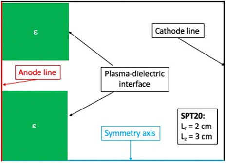
Figure 1. Computational domain with boundary conditions.
Figure 2 shows the typical PIC/TPMC flowchart used for the HT simulation with typical input data exchanged between the PIC and TPMC modules. Table 1 summarizes the simulation parameters used for the cases analyzed in Section 3.
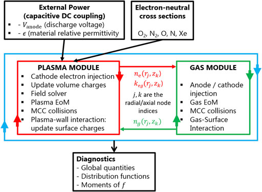
Figure 2. Flowchart of the present Hall thruster PIC-TPMC model.
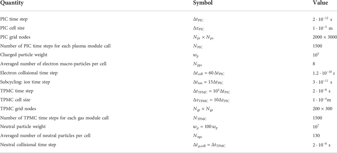
Table 1. Simulation parameters used for the present PIC-DSMC model.
The plasma and gas modules inside the code workflow (Figure 2) are separately and sequentially solved due to the very different time scales characteristic of the plasma and gas dynamics [21]. Inside the plasma module (Section 2.1), the typical PIC tasks (free flight of the charged particles, field solver, and bulk/surface collisional processes) are iterated using a small time step (
The two different PIC plasma and TPMC gas modules with their unique tasks are detailed in the following sub-sections.
The model presented in this work simulates the full plasma discharge evolution starting from the gas breakdown to plasma sustainment in a steady-state condition. Initially, the simulation domain is empty with only gas particles from the first TPMC module call (Section 2.2). A fixed prescribed number of macro-electrons is initially injected into the plume region and the electron multiplication cascade occurs, leading to gas breakdown. When a macroscopic ion current is detected at the outflow boundary (the cathode line in Figure 1), the electron current injected into the plume is automatically set as equal to the total current collected at the anode
This guarantees that the total current computed at the outflow boundary is globally zero, leading to a perfectly neutralized flow at all timesteps. In the steady-state condition, the anode (or discharge) current Id must be equal to the cathode current Ie,inj, that partially enters the discharge channel to sustain it and partially enters the plume to neutralize the ion plume current (see Figure 3). The latter condition is not forced but verified during the simulation. Therefore, the discharge current is not a priori prescribed in the simulation but is instead computed self-consistently, resulting in a function of the imposed working conditions: discharge voltage, magnetic field, mass flow rate, and chemical composition of the gas propellant.
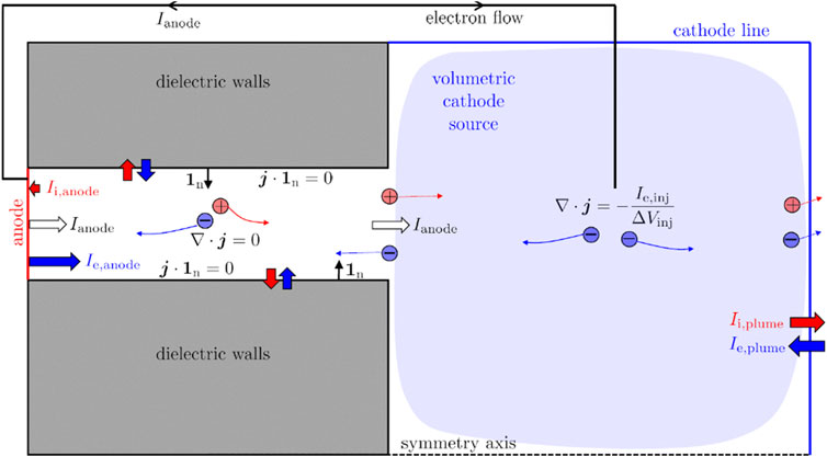
Figure 3. Scheme representing the electron injection scheme used in the model.
Due to the axisymmetric nature of the simulation, the electron emission from the out-of-axis cathode location cannot be reproduced and the electrons are injected uniformly in position (by considering the cylindrical metrics) in the plume region, with a full Maxwellian distribution in the velocity space, which is characterized by a temperature Te0 = 2 eV. Electron macro-particles, just like ions, are eliminated from their respective particle lists, whenever they cross a simulation boundary, including an external boundary of the simulation domain or a material boundary. The current version of the code does not perform selective reflection (based on the electron kinetic energy) at the downstream boundaries, as done in other reports [22, 23]. Consequently, a numerical plasma sheath develops close to the downstream boundary to guarantee a perfect local ambipolar current condition.
At each PIC time step, the electron charge is deposited on the four cell nodes through an area weighting interpolation function. When the electric field is solved on the mesh (Section 2.1.1), it is interpolated back to the particle location by using the same interpolation function. The Boris algorithm is used to integrate the Lorentz force and the particles are moved according to the leapfrog method [15]. Due to the large ion mass (according to the propellant used in this study), a subcycling method is used to move ions and deposit their charge to the nodes only every 15 electron PIC cycles (
Anomalous electron transport contributions due to azimuthal fluctuations are considered as additional scattering with a prescribed frequency
where the fitting coefficient k is set to 0.2 by matching the results of experimental measurements obtained using Xe as a propellant [24]. The anomalous collision output velocity is computed as for an elastic isotropic one, although a recent study demonstrated how the isotropic and anisotropic characters of anomalous scattering can lead to different discharge characteristics [25]. The transport due to electron-wall interaction (so-called near-wall conductivity) is self-consistently considered due to the radial nature of the simulation.
Finally, the model implemented no numerical tricks (reduced ion mass, increased vacuum permittivity [26], or geometrical scaling [27]) to accelerate the execution time of the simulation.
The Poisson equation is solved in both the plasma and the dielectric material regions (green regions in Figure 1) to consider the effect of the relative permittivity
If integrated in a volume
where
where (assuming
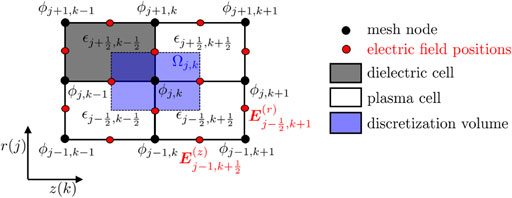
Figure 4. Scheme representing the Poisson equation discretization used in the model.
On the axis of symmetry (
At the remaining boundaries (the cathode and anode lines), simple Dirichlet conditions are applied. The linear algebraic system derived from Eq. 4 (and including the boundary conditions) is finally solved using the Petsc package [28].
When an electron strikes the dielectric wall, the number of secondary electrons emitted is selected from the Vaughan formula [29].
using the following fitting parameters corresponding to BNSiO2:
All ions hitting the dielectric surfaces are deleted from the particle list since they are assumed to be neutralized and re-injected from the dielectric surfaces as neutrals. A counter is activated to update the flux of the different neutral species g (henceforth with g or G we will denote the generic neutral species used in the present study, N, N2, O, O2, or Xe) at the inner iw and outer ow walls as a function of the axial location
For simplicity, the present model simulates only electron-gas collisions. Previous HT studies showed the negligible effect of Coulomb processes involving electron and ion species [18], while ion-neutral collisions have a relevant impact on the plume expansion and plume-spacecraft interactions. For electron-atom collisions, elastic scattering, electronic excitation, and single ionization are considered, while vibrational excitations, dissociation, and dissociative ionization are additionally considered for electron-molecule collisions. Collisions between electron and molecular oxygen O2 also provide the possibility to include the production of negative ions O− through the dissociative attachment process. The production of multiply charged ions of atoms and molecules is neglected due to the low power range investigated.
An important assumption, valid for low-pressure plasmas, is that the neutral particle target G is always found by the electron projectile in the electronic ground states since the spontaneous relaxation from an electronically excited state
is considered to be much faster than the electron collisional time [32]. This is true for radiative excited states, but not for metastable states. The possible implications of two-step ionization processes (ionization of metastable states) will be investigated in the future by adding metastable states to the ground state in the gas module. In addition, the vibrational kinetics of molecules are deactivated and all the molecules are considered to be in their vibrational ground level ν = 0.
The different cross-sections used in the model are reported and discussed in Section 2.1.3.1, while the Monte Carlo algorithm used for the electron-neutral collisions is presented in Section 2.1.3.2.
This section presents the different electron-induced processes involving the air species (N, N2, O, and O2) and Xe included in the model. The corresponding cross-sections are also discussed.
Detailed overviews of the relevant cross-sections with nitrogen species are given in Brunger and Buckman [33], Itikawa [34], Tabata et al. [35, 36], Thorsteinsson and Gudmundsson [30], and Kawaguchi et al. [37]. The complete reaction set used in the present model is reported in Table 2.
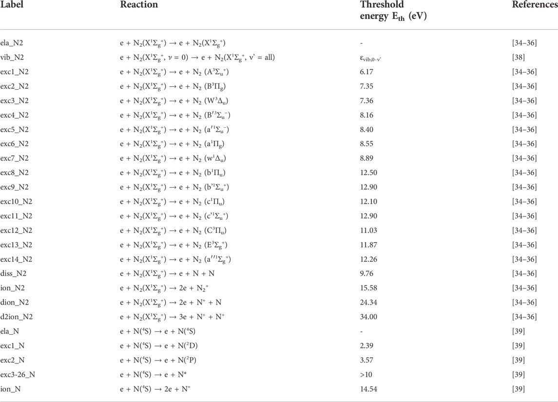
Table 2. Reactions between electron and the neutral nitrogen species (N2 and N) considered in the proposed PIC-TPMC model.
The cross-section for elastic scattering by the molecular ground state N2(X1Σg+) is taken from [34–36]. The vibrational excitation cross-section corresponds to the sum of the transitions from ν = 0 to all possible final states [38]. In our model, we have considered the electron impact excitation of the following 14 electronic excited states of the nitrogen molecule [34–36]: A3Σu+, B3Πg, W3Δu, B′3Σu−, a′1Σu−, a1Πg, w1Δu, b1Πu, b'1Σu+, c1Πu, c'1Σu+, C3Πu, E3Σg+, and a′′1Σg+. Furthermore, we assumed that the total molecular dissociation cross-section includes three channels: 1) a resonant dissociation through the intermediation of the unstable nitrogen negative ion N2 + e → (N2−)* → 2N + e leading to a sharp narrow peak around 10 eV; 2) predissociation; i.e., excitation to certain electronic and vibrational states that automatically dissociate into two nitrogen atoms by an internal conversion from an excited state towards a repulsive dissociative state [40]; and 3) the remaining contributions for
The cross-section for elastic scattering by the atomic nitrogen ground state N(4S) is taken from [39]. In addition to atomic excitations to the N(2D) state at 2.39 eV and to the N(2P) state at 3.57 eV, 24 other electronic excitations with thresholds >10 eV are considered [39]. The cross-section for atomic ionization (at 14.54 eV) is taken from [39].
The cross-sections for the collisions between electron and the oxygen species (O and O2) were presented by Brunger and Buckman [33], Itikawa [41], Vahedi and Surendra [42], Gudmundsson et al. [31], and Vass et al. [43]. The complete reaction set is reported in Table 3.
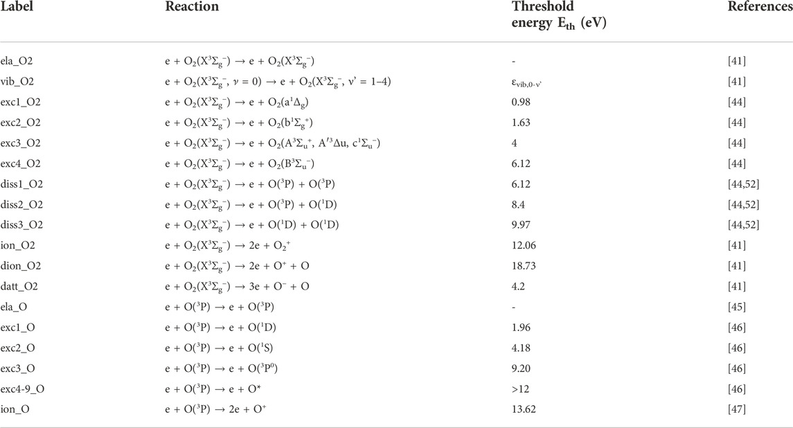
Table 3. Reactions between electron and the neutral oxygen species (O2 and O) considered in the proposed PIC-TPMC model.
The cross-section used for the elastic scattering of electrons by the ground state of the oxygen molecule O2(X3Σg−) is that recommended by Itikawa [41]. The vibrational cross-section of O2 shows completely different behavior in the energy regions above and below 1 eV. At energies >1 eV, the cross-section shows a broad peak at about 10 eV. At 0.2–1 eV, the cross-section consists of a set of very sharp peaks due to a temporary electron capture of O to form a negative ion state O−(2Πg). In between, the cross-section value is very small. Here, we have included the contributions of four different transitions ν = 0 → 1-4 and neglected the resonant peaks due to their small width and energy range compared to the typical electron energies in HT. The cross-sections for the excitations [44] to the two metastable O2(a1Δg) (energy threshold 0.98 eV) and O2(b1Σg+) (energy threshold 1.63 eV) are distinguished while the excitations to the three states O2(A3Σu+), O2(A′3Δu), and O2(c1Σu−) are represented as a unique cross-section since the corresponding threshold energies (≈4 eV) are very close. Finally, the electron energy loss spectrum for O2 electronic excitation shows a broad peak ranging from 7 to 9.5 eV. This is called the Schumann-Runge (SR) continuum and is caused by the excitation of the O2(B3Σu−) state. Its energy threshold is 6.12 eV. The excitation of the SR continuum also contributes to a neutral dissociation O2(B3Σu−) → O(3P) + O(1D). The cross-sections for the electron-impact dissociation of the oxygen molecule are taken from [44]. The excitation to the 6.12 eV level leads to dissociation into O(3P) + O(3P), excitation to the 8.4 eV level leads to dissociation into O(3P) + O(1D), and excitation to the 9.97 eV level leads to dissociation into O(1D) + O(1D). The corresponding released energy magnitudes to each pair of heavy fragments are 1.03 eV, 1.27 eV, and 0.88 eV, respectively. The cross-sections for electron-impact and dissociative ionization of the oxygen molecule ground state are taken from Itikawa [41] and the corresponding ionization potential are 12.06 eV and 18.73 eV, respectively. For the dissociative attachment from the ground state oxygen molecule, the cross-section is taken from Itikawa [41]. The threshold energy is 4.2 eV. The incident electron loses its energy, which is absorbed by the oxygen molecule to form O2−, which subsequently dissociates to form the fragments O and O−. The potential energy for the O+ O− pair is 3.63 eV above the ground state potential for O2. The remaining incident electron energy (Einc - 3.63) eV is divided between the two fragments.
The cross-section for elastic collisions of electrons with oxygen atoms is taken from Itikawa and Ichimura [45]. The cross-sections for electron-impact excitation of the atomic oxygen ground 3P state to the 1D, 1S, and 3P0 excited states and to the Rydberg 5S0, 3S0, 5P, 3P, 5D0, and 3D0 states are taken from Laher-Gilmore [46]. The cross-section for electron-impact ionization is taken from [47]. The ionization potential is 13.62 V.
Finally, the electron-Xe reaction set (Table 4) includes the elastic momentum transfer of the Xe ground state 5p6 1S0 showing the typical Ramsauer minimum at 0.62 eV and 74 electronic excitations from 8.32 eV to 12.58 eV taken from [39]. Finally, the single ionization of the Xe ground state with an energy threshold of 12.13 eV is from Hayashi [44].
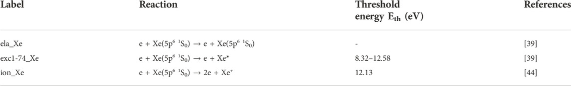
Table 4. Reactions between electrons and Xe in the proposed PIC-TPMC model.
All cross-sections used in the model are reported in Figures 5A–E.
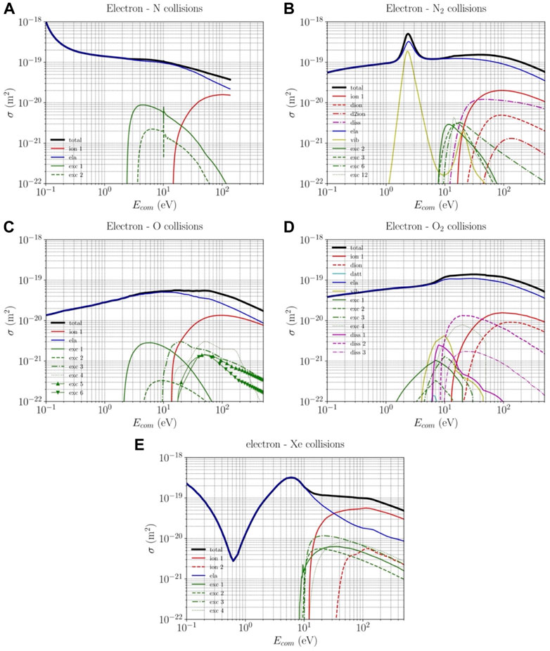
Figure 5. Electron-neutral collision cross-sections used in the model for (A) atomic nitrogen N, (B) molecular nitrogen N2, (C) atomic oxygen, (D) molecular oxygen O2, and (E) xenon.
The collision probability of the ith electron can be written as [16].
where
The sum of the vibrational and electronic excitations and for the dissociation in Eq. 11 includes all possible channels (Table 3) for these reactions.
The null Monte Carlo collision method [42] is used to save computational time and the Nanbu method [48] simultaneously determines:
1) whether an electron collides
(henceforth, R01 is a generic random number uniformly distributed in the range [0,1]);
2) which gas species
3) which particular collisional event c occurs among the total
The Monte Carlo module is called every 60 PIC cycles (
Under the cold gas approximation used (the gas-particle velocity is much smaller than the electron velocity), the relative and electron velocities are equal. Neglecting the electron mass compared to the neutral mass
where
In the case of an ionization event (single ionization for an atom and molecule or dissociative ionization for a molecule) the total post-collisional energy is equally distributed between the scattered (parent) and ejected (progeny) electrons:
where
The velocity components of the ion byproduct are sampled from a full Maxwellian distribution with the local temperature
In the last MCC call of the PIC module iteration, the reaction rate constant of the different collisional events l of the electron-g collision
is calculated [here the brackets refer to the average over all electrons belonging to the home cell centered around the location
During the neutral module iteration, gas particles are allowed to enter the simulation domain from the anode location and from the inner and outer wall (with an axial-dependent flux
Once injected, neutral macro-particles move in straight lines until they experience a collision (see Section 2.2.1), hit the walls, or exit the simulation domain.
For every ith gas particle of the
where the electron density
• elastic and excitation events: the neutral particle velocity and internal energy level (vibrational and electronic) remain unchanged;
• dissociation (dissociative ionization) event: two atoms (one atom) are (is) created and the molecule is deleted from the particle list; the total energy available (depending on the actual dissociation channel) is randomly distributed between the two by-products and they are assumed to be isotropically scattered.
• ionization event: the neutral particle is simply removed from the neutral particle list.
Due to the low-pressure regime, the possible gas-gas processes are not considered.
The HT configuration selected in the present study corresponds to a low-power SPT-20 HT type [14]. This decision is suggested by the need to minimize the size of the full satellite system to reduce the drag to be compensated and the propellant mass flow rate required to operate. The channel length is
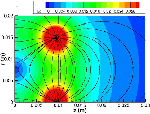
Figure 6. Magnetic field topology (streamlines in black and B field magnitude in Tesla) used for all analyzed cases.
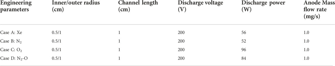
Table 5. Engineering parameters used for the SPT20 simulations.
Figure 7 shows the two-dimensional plots of the most relevant HT plasma and gas parameters for the Xe propellant case (Case A): 1) electric potential

Figure 7. Two-dimensional maps of the most relevant HT plasma and gas parameters for the SPT20 nominal case using Xe (case A) as the propellant: (A) electric potential
The maps demonstrate the main features of the typical HT discharge and plume. The results are strongly correlated with the magnetic field topology used: most of the electric field is concentrated near the exhaust, where the neutral density is so low (
This section compared cases using N2 (case B), O2 (case C) and N2-O mixture (case D, with 50%–50% in terms of mass flow rate and corresponding to the air composition at an altitude of approximately 200 km) as propellants to the nominal case using Xe (case A), focusing on plasma and performance parameters, which are summarized in Table 6. Case D does not consider air composition changes due to the gas dynamics inside the intake, which can lead to the possible formation of N, O2, and NO species entering the thruster channel discharge from the anode [49].
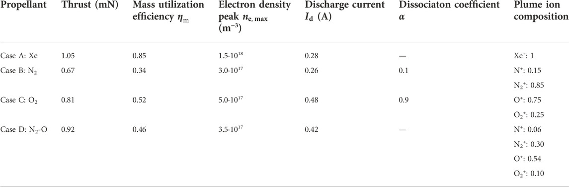
Table 6. Global performance and main plasma parameters corresponding to the different propellants.
Figures 8–10 report the same plasma and gas parameters of Figure 7 for cases B, C, and D, respectively. The dissociation coefficient for cases B and C is defined as the ratio between the atomic and total (atomic G and molecular parent G2) gas density averaged over the entire computational domain
while the mass utilization efficiency
with
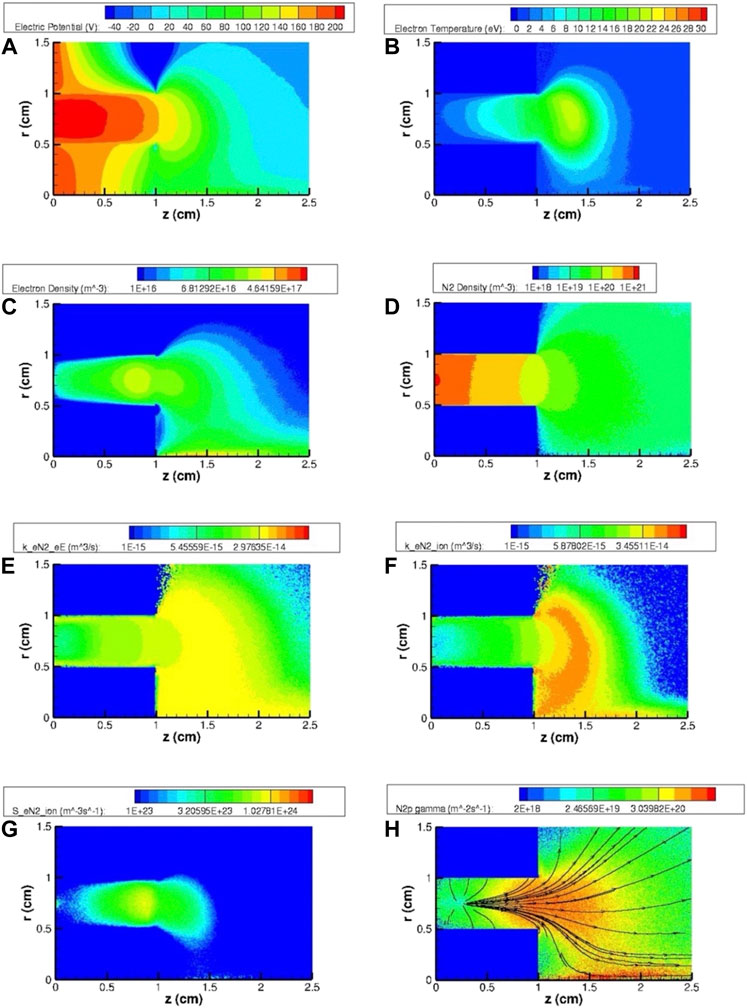
Figure 8. Two-dimensional maps of the most relevant HT plasma and gas parameters for the SPT20 nominal case using N2 (case B) as the propellant: (A) electric potential
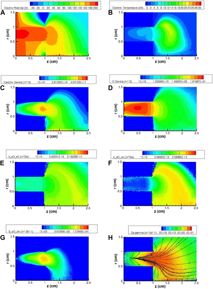
Figure 9. Two-dimensional maps of the most relevant HT plasma and gas parameters for the SPT20 nominal case using O2 (case C) as the propellant: (A) electric potential
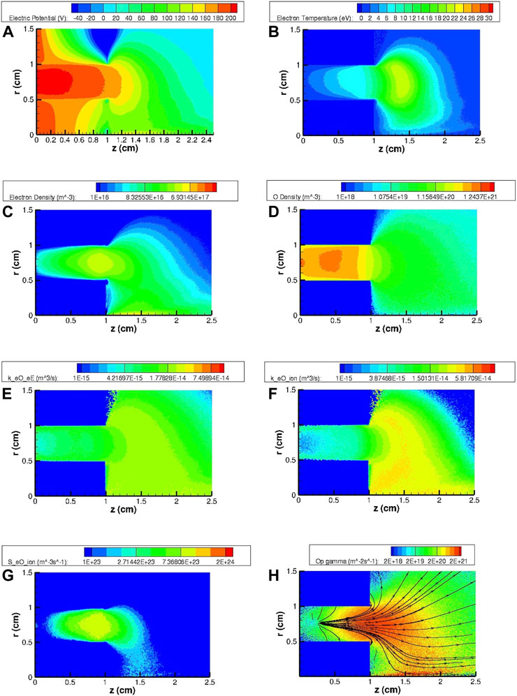
Figure 10. Two-dimensional maps of the most relevant HT plasma and gas parameters for the SPT20 nominal case using N2 and O (case D) as the propellant: (A) electric potential
The most evident result is that the thrust values for all air species propellants (cases B, C, and D) are lower than the corresponding values relative to the Xe propellant (case A). The main reason is ascribed to the lower mass utilization efficiency
1) Lower ionization reaction rate coefficient
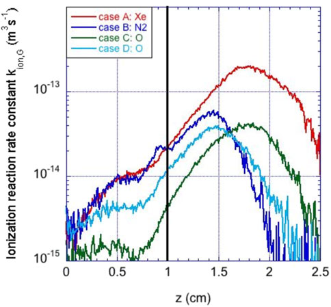
Figure 11. Axial profiles along the channel thruster centerline of the ionization reaction rate coefficient
2) Nitrogen N2 and oxygen O2 molecules are lighter (approximately five-fold) than Xe atoms, which directly affect the thrust (for a given total thrust efficiency and discharge power, ions that are exhausted faster produce a lower thrust) but also indirectly affect the ionization efficiency. The faster the neutral propellant particles, the smaller their transit time through the channel, reducing their chance of being ionized by the electron cloud. The corresponding ionization mean free path
is larger, thus reducing the propellant mass utilization, for a given thruster chamber length. The ion mean free path is further increased by a smaller electron density
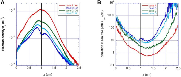
Figure 12. Axial profiles along the channel thruster centerline with (A) electron density
To better understand this point, Figure 12 shows the axial profiles along the channel thruster centerline of the 1) electron density
with
3) Additional reaction channels lead to extra electron power losses (alternative to ionization). Table 7 and Figure 13 report the repartition of the total power spent by electrons in the main gas propellant collisional channels for the different cases. Although the power losses in molecular vibrational MeV excitations are negligible (
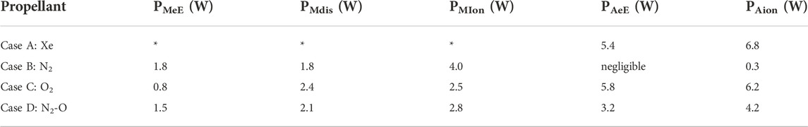
Table 7. Electron power loss (W) repartition in the main collisional molecular (MeE-electronic excitation, Mdis-dissociation, and Mion-ionization) and atomic (AeE-electronic excitation and Aion-ionization) channels for the different propellants.
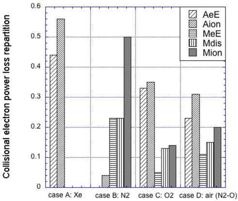
Figure 13. Repartition of the electron power losses (normalized to the total collisional power loss) among the main electron-gas collisional channels (MeE: molecular electronic excitation, Mdis: molecular dissociation, Mion: molecular ionization, AeE: atomic electronic excitation, and Aion: atomic ionization) for the different cases.
This study has developed a PIC-TPMC model to simulate the coupling between plasma and gas in HTs when using molecular propellants that are relevant for air-breathing applications. The model features two different alternating modules for plasma species (PIC) and neutral gas species (TPMC), which are iterated and coupled until convergence. The PIC module features standard algorithms, except for the Poisson solver, which computes the electric potential solution within the dielectric material through a generalized Poisson equation formulation. This allows the use of more realistic boundary conditions. Collisional events include electron-neutral collisions and have been modeled through the well-known null-collision method (against a background of frozen non-uniform neutrals) within the PIC module and using pre-computed (from the PIC) collisional rates for the TPMC module (against a background of frozen non-uniform electrons). A large variety of collisional processes are included; among these, elastic scattering, electronic excitation, and single ionization are considered for collisions with atoms, while vibrational excitations, dissociation, and dissociative ionization are additionally simulated for collisions with molecules (by adding the dissociative electron attachment for O2).
The model has demonstrated how the degradation of the thruster performance compared to the nominal case using Xe can be ascribed mainly to the lower elementary mass of the molecular propellants. This produces a lower propellant mass utilization (and, hence, thrust efficiencies) for a fixed thruster chamber length. The results show that the latter must be elongated by factors of 4 and 10 for O2 and N2/air propellants, respectively, to provide more efficient ionization of molecular and atomic by-products.
The Xe propellant case shows a total power dissipated towards ionization larger than 55%. No other air-species propellants show such a large value due to additional electron energy collisional loss channels. The main losses are due to dissociation (only partially compensated by the following atomic ionization) for O2 and molecular electronic excitation and dissociation (equally distributed) for N2.
Finally, this work has assumed that the molecules are in their vibrational ground states and has not considered all the possible metastable states of the atoms and molecules. Additional studies are needed to investigate the role of non-equilibrium vibrational kinetics for molecules and metastable electronic states for atoms and molecules, which may be relevant for the selected propellants and increase the overall efficiency of the molecular propellant cases, through stepwise ionization [51]. Further research is also needed to address unexplored physical phenomena such as the role of ion-induced secondary electron emission or ion/neutral collisions, which have been neglected in the present work.
The raw data supporting the conclusion of this article will be made available by the authors without undue reservation.
FT developed the code and analyzed the results of the model. PM implemented the algorithm to solve the Poisson equation. All authors contributed to the writing of this article.
This work was funded by the Italian Ministry of University and Research (MUR) (project PON “CLOSE to the Earth”, No. ARS ARS01–00141).
The authors declare that the research was conducted in the absence of any commercial or financial relationships that could be construed as a potential conflict of interest.
All claims expressed in this article are solely those of the authors and do not necessarily represent those of their affiliated organizations, or those of the publisher, the editors, and the reviewers. Any product that may be evaluated in this article, or claim that may be made by its manufacturer, is not guaranteed or endorsed by the publisher.
1. O’Reilly D, Herdrich G, Kavanagh DF. Electric propulsion methods for small satellites: A review. Aerospace (2021) 8(22). doi:10.3390/aerospace8010022
2. Szabo J, Pote B, Paintal S, Robin M, Hillier A, Branam RD, et al. Performance evaluation of an iodine-vapor Hall thruster. J Propuls Power (2012) 28:848–57. doi:10.2514/1.B34291
3. Schwertheim A, Knoll A. Low power thrust measurements of the water electrolysis Hall effect thruster. CEAS Space J (2021) 14:3–17. doi:10.1007/s12567-021-00350-y
4. Schönherr T, Komurasaki K, Romano F, Massuti-Ballester B, Herdrich G. Analysis of atmosphere-breathing electric propulsion. IEEE Trans Plasma Sci (2015) 43(1):287–94. doi:10.1109/TPS.2014.2364053
5. Zheng P, Wu J, Zhang Y, Biqi W. A comprehensive review of atmosphere-breathing electric propulsion systems. Int J Aerospace Eng (2020) 2020:1–21. doi:10.1155/2020/8811847
6. Romano F, Espinosa-Orozco J, Pfeiffer M, Herdrich G, Crisp N, Roberts P, et al. Intake design for an atmosphere-breathing electric propulsion system (ABEP). Acta Astronaut (2021) 187:225–35. doi:10.1016/j.actaastro.2021.06.033
7. Ferrato E, Giannetti V, Tisaev M, Lucca Fabris A, Califano F, Andreussi T. Rarefied flow simulation of conical intake and plasma thruster for very low earth orbit spaceflight. Front Phys (2022) 2022:823098. doi:10.3389/fphy.2022.823098
8. Singh LA, Walker MLR. A review of research in low Earth orbit propellant collection. Prog Aerospace Sci (2015) 75:15–25. doi:10.1016/j.paerosci.2015.03.001
9. Gurciullo A, Fabris AL, Cappelli MA. Ion plume investigation of a Hall effect thruster operating with Xe/N2 and Xe/air mixtures. J Phys D: Appl Phys (2019) 52:464003. doi:10.1088/1361-6463/ab36c5
10. Marchioni F, Cappelli MA. Extended channel Hall thruster for air-breathing electric propulsion. J Appl Phys (2021) 130:053306. doi:10.1063/5.0048283
11. Taploo A, Lin L, Keidar M. Analysis of ionization in air-breathing plasma thruster. Phys Plasmas (2021) 28:093505. doi:10.1063/5.0059896
12. Garrigues L. Computational study of Hall-effect thruster with ambient atmospheric gas as propellant. J Propuls Power (2012) 28(2):344–54. doi:10.2514/1.B34307
13. Pekker L, Keidar M. Analysis of airbreathing Hall-effect thrusters. J Propuls Power (2012) 28(6):1399–405. doi:10.2514/1.B34441
14. Loyan AV, Maksymenko TA. Performance investigation of SPT-20M low power Hall effect Thruster. In: IEPC-2007-100 paper, 30th International Electric Propulsion Conference; September 17-20, 2007; Florence, Italy (2007).
15. Tskhakaya D, Matyash K, Schneider R, Taccogna F. The particle-in-cell method. Contrib Plasma Phys (2007) 47(8-9):563–94. doi:10.1002/ctpp.200710072
16. Taccogna F. Monte Carlo Collision method for low temperature plasma simulation. J Plasma Phys (2015) 81(1):305810102. doi:10.1017/S0022377814000567
17. Taccogna F, Longo S, Capitelli M, Schneider R. Stationary plasma thruster simulation. Comput Phys Commun (2004) 164(1-3):160–70. doi:10.1016/j.cpc.2004.06.025
18. Taccogna F, Longo S, Capitelli M, Schneider R. Surface-driven asymmetry and instability in the acceleration region of Hall thruster. Contrib Plasma Phys (2008) 48(4):375–86. doi:10.1002/ctpp.200810061
19. Taccogna F, Minelli P. Three-dimensional particle-in-cell model of Hall thruster: The discharge channel. Phys Plasmas (2018) 25(6):061208. doi:10.1063/1.5023482
20. Taccogna F, Minelli P, Asadi Z, Bogopolsky G. Numerical studies of the ExB electron drift instability in Hall thrusters. Plasma Sourc Sci Technol (2019) 28(6):064002. doi:10.1088/1361-6595/ab08af
21. Taccogna F, Minelli P, Bruno D, Longo S, Schneider R. Kinetic divertor modeling. Chem Phys (2012) 398:27–32. doi:10.1016/j.chemphys.2011.04.004
22. Jambunathan R, Levin DA. A self-consistent open boundary condition for fully kinetic plasma thruster plume simulations. IEEE Trans Plasma Sci (2020) 48(3):610–30. doi:10.1109/tps.2020.2968887
23. Li M, Merino M, Ahedo E, Haibin T. On electron boundary conditions in PIC plasma thruster plume simulations. Plasma Sourc Sci Technol (2019) 28(3):034004. doi:10.1088/1361-6595/ab0949
24. Taccogna F, Garrigues L. Latest progress in Hall thrusters plasma modelling. Rev Mod Plasma Phys (2019) 3(1):12–63. doi:10.1007/s41614-019-0033-1
25. Marín-Cebrián A, Domínguez-Vázquez A, Fajardo P, Ahedo E. Macroscopic plasma analysis from 1D-radial kinetic results of a Hall thruster discharge. Plasma Sourc Sci Technol (2021) 30(11):115011. doi:10.1088/1361-6595/ac325e
26. Szabo J, Warner N, Martinez-Sanchez M, Batishchev O. Full particle-in-cell simulation methodology for axisymmetric Hall effect thrusters. J Propuls Power (2014) 30(1):197–208. doi:10.2514/1.B34774
27. Taccogna F, Longo S, Capitelli M, Schneider R. Self-similarity in Hall plasma discharges: Applications to particle models. Phys Plasmas (2005) 12(5):053502. doi:10.1063/1.1877517
28. Balay S, Abhyankar S, Adams M, Brown J, Brune P, Buschelman K, et al. PETSc users manual (2019).
29. Villemant M, Belhaj M, Sarrailh P, Dadouch S, Garrigues L, Boniface C. Measurements of electron emission under electron impact on BN sample for incident electron energy between 10 eV and 1000 eV. Europhys Lett (2019) 127:23001. doi:10.1209/0295-5075/127/23001
30. Thorsteinsson EG, Gudmundsson GT. A global (volume averaged) model of a nitrogen discharge: I. Steady state. Plasma Sourc Sci Technol (2009) 18:045001. doi:10.1088/0963-0252/18/4/045001
31. Gudmundsson JT, Kawamura E, Lieberman MA. A benchmark study of a capacitively coupled oxygen discharge of the oopd1 particle-in-cell Monte Carlo code. Plasma Sourc Sci Technol (2013) 22:035011. doi:10.1088/0963-0252/22/3/035011
32. Liebermann LA, Lichtenberg AJ. Principles of plasma discharges and materials processing. 2nd ed. Hoboken, NJ, USA: Wiley (2005).
33. Brunger MJ, Buckman SJ. Electron–molecule scattering cross-sections. I. Experimental techniques and data for diatomic molecules. Phys Rep (2002) 357:215–458. doi:10.1016/S0370-1573(01)00032-1
34. Itikawa Y. Cross sections for electron collisions with nitrogen molecules. J Phys Chem Ref Data (2006) 35:31–53. doi:10.1063/1.1937426
35. Tabata T, Shirai T, Sataka M, Kubo H. Analytic cross sections for electron impact collisions with nitrogen molecules. Data Nucl Data Tables (2006) 92:375–406. doi:10.1016/j.adt.2006.02.002
36. Tabata T, Shirai T, Sataka M, Kubo H. Erratum to “Analytic cross sections for electron impact collisions with nitrogen molecules” [At. Data Nucl. Data Tables 92 (2006) 375–406]. Data Nucl Data Tables (2011) 98:74. doi:10.1016/j.adt.2011.06.002
37. Kawaguchi S, Takahashi K, Satoh K. Electron collision cross section set for N2 and electron transport in N2, N2/He, and N2/Ar. Plasma Sourc Sci Technol (2021) 30:035010. doi:10.1088/1361-6595/abe1d4
38. Laporta V, Little DA, Celiberto R, Tennyson J. Electron-impact resonant vibrational excitation and dissociation processes involving vibrationally excited N2 molecules. Plasma Sourc Sci Technol (2014) 23:065002. doi:10.1088/0963-0252/23/6/065002
39. BSR database. BSR database (2022). Available from: www.lxcat.net (Accessed June 9, 2022).
40. Lewis BR, Gibson ST, Zhang W, Lefebvre-Brion H, Robbe J-M. Predissociation mechanism for the lowest 1Πu states of N2. J Chem Phys (2005) 122:144302. doi:10.1063/1.1869986
41. Itikawa Y. Cross sections for electron collisions with oxygen molecules. J Phys Chem Ref Data (2009) 38:1–20. doi:10.1063/1.3025886
42. Vahedi V, Surendra M. A Monte Carlo collision model for the particle-in-cell method: Applications to argon and oxygen discharges. Comput Phys Commun (1995) 87:179–98. doi:10.1016/0010-4655(94)00171-w
43. Vass M, Wilczek S, Lafleur T, Brinkmann RP, Donkó Z, Schulze J. Electron power absorption in low pressure capacitively coupled electronegative oxygen radio frequency plasmas. Plasma Sourc Sci Technol (2020) 29:025019. doi:10.1088/1361-6595/ab5f27
44. Biagi database. Biagi database (2022). Available from: www.lxcat.net (Accessed June 9, 2022).
45. Itikawa Y, Ichimura A. Cross sections for collisions of electrons and photons with atomic oxygen. J Phys Chem Ref Data (1990) 19:637–51. doi:10.1063/1.555857
46. Laher RR, Gilmore FR. Updated excitation and ionization cross sections for electron impact on atomic oxygen. J Phys Chem Ref Data (1990) 19:277–305. doi:10.1063/1.555872
47. Bell KL, Gilbody HB, Hughes JG, Kingston AE, Smith FJ. Recommended data on the electron impact ionization of light atoms and ions. J Phys Chem Ref Data (1983) 12:891–916. doi:10.1063/1.555700
48. Nanbu K. Probability theory of electron-molecule, ion-molecule, molecule-molecule, and Coulomb collisions for particle modeling of materials processing plasmas and cases. IEEE Trans Plasma Sci (2000) 28(3):971–90. doi:10.1109/27.887765
49. Parodi P. Analysis and simulation of an intake for air-breathing electric propulsion systems. Graduation thesis. Pisa, Italy: Aerospace engineering department, University of Pisa (2019).
50. Morozov AI, Melikov IV. Similitude in Hall-current plasma accelerators. Soviet Physics-Technical Phys (1974) 19:340–2.
51. Yamashita Y, Tsukizaki R, Nishiyama K. Importance of stepwise ionization from the metastable state in electron cyclotron resonance ion thrusters. J Electr Propuls (2022) 1:2. doi:10.1007/s44205-022-00002-1
Keywords: kinetic particle-in-cell modeling, test particle Monte Carlo gas dynamics, low power Hall thruster, air-breathing electric propulsion, molecular propellant
Citation: Taccogna F, Cichocki F and Minelli P (2022) Coupling plasma physics and chemistry in the PIC model of electric propulsion: Application to an air-breathing, low-power Hall thruster. Front. Phys. 10:1006994. doi: 10.3389/fphy.2022.1006994
Received: 29 July 2022; Accepted: 21 September 2022;
Published: 19 October 2022.
Edited by:
Amar Prasad Misra, Visva-Bharati University, IndiaReviewed by:
Hui Liu, Harbin Institute of Technology, ChinaCopyright © 2022 Taccogna, Cichocki and Minelli. This is an open-access article distributed under the terms of the Creative Commons Attribution License (CC BY). The use, distribution or reproduction in other forums is permitted, provided the original author(s) and the copyright owner(s) are credited and that the original publication in this journal is cited, in accordance with accepted academic practice. No use, distribution or reproduction is permitted which does not comply with these terms.
*Correspondence: Francesco Taccogna, ZnJhbmNlc2NvLnRhY2NvZ25hQGNuci5pdA==
Disclaimer: All claims expressed in this article are solely those of the authors and do not necessarily represent those of their affiliated organizations, or those of the publisher, the editors and the reviewers. Any product that may be evaluated in this article or claim that may be made by its manufacturer is not guaranteed or endorsed by the publisher.
Research integrity at Frontiers
Learn more about the work of our research integrity team to safeguard the quality of each article we publish.