- 1PowerChina Huadong Engineering Corporation Limited, Hangzhou, China
- 2HydroChina Itasca R&D Center, Hangzhou, China
An installation platform will disturb the natural seabed adjacent to a monopile and, consequently, affects the bearing capacity of the monopile foundation. Thus, consideration of the influence of installation disturbance is required in the monopile design, which can also save a fraction of the construction costs and avoid security risks. It was found in a sensitivity analysis, depending on the numerical simulations for an offshore monopile foundation installed using an installation platform, that the bearing capacities of the monopile were reduced by the penetration and extraction of the support legs of the installation platform, which were, a reduction of about 7% of the horizontal bearing capacity of the monopile (decreasing with a larger diameter of the monopile), about 2% of the ultimate bending moment, and almost no reduction of the vertical bearing capacity. For the monopile specifically subjected to the combined loads, it was found in SLS that horizontal displacement and rotation at the mudline increased by about 5.13% and 2.12%, respectively, and internal forces increased by about 3.29%–9.87%; and the horizontal displacement and the rotation at the mudline increased by about 4.56% and 2.79% in ULS, respectively, and the internal forces increased by about 3.49%–7.79% in the ULS. The study on the effects of the disturbance of the installation platform can be an important suggestion for the engineer in monopile design.
1 Introduction
In recent years, large-diameter monopile foundations were widely used in offshore wind power projects taking full account of their simple structure, simple manufacturing, and convenient construction. Statistics indicated that the monopile foundation accounted for more than 80% of offshore wind power foundations [1]. A monopile with a large diameter can ensure the stability of itself and the wind power generator in extreme conditions. DNVGL-ST-0126 represented a criterion, which indicated that the rotation at the top of the monopile foundation must be smaller than 0.25 grad during the operation [2]. In this background, an accurate estimation of the bearing capacity of the monopile foundation under various load conditions is relatively important.
Besides the experiments onsite, the bearing capacity of the monopile foundation can be determined depending on the beam–spring model, which can determine the soil reaction curves (SRCs) and in which the monopile is simplified as the beam element coupling to a series of soil springs. The lateral displacements of the monopile as a relevant design indicator in the m-method [3], p-y method [4], and elastoplastic method [5] are used to determine the lateral bearing capacity. However, these methods are not capable of considering the shaft friction, the bending moment at the pile base, and the base shear force, which are beneficial to improve the lateral bearing capacity of the monopile with a large diameter. Thus, they were modified depending on the laboratory tests by some researchers. Xing et al. modified the conventional strain wedge model and proposed a method based on the modification to determine the lateral bearing capacity of the monopile [6]. Zhuang et al. represented that the pile diameter and the stiffness of the soil surrounding the monopile were dominant to determine the lateral bearing capacity, and suggested increasing the pile diameter, improving the shallow soil layer, and using the cushion to improve the lateral bearing capacity.
Besides the abovementioned methods, the numerical methods, i.e., finite element method (FEM) and discrete element method (DEM), are widely accepted and applied in geotechnical engineering. Liu et. al. simulated the performance of an offshore monopile foundation in the program Abaqus, compared the results to the measured data onsite, and found that soil plugging can improve the bearing capacity of the pile foundation [7]. After determining the lateral bearing capacity of an offshore large-diameter monopile under high-frequency vibration by using the FEM, Zhang et. al. proposed a reduction factor for the monopile under the cyclic loading and found that the embedded depth was more dominant in calculating the lateral bearing capacity than the pile diameter [8]. Li et. al. found that the vertical loading affected the lateral bearing capacity by a few, depending on the numerical simulation in the program FLAC3D; seabed scours reduced the lateral bearing capacity of the monopile. Meanwhile, the location of the maximum moment moved down [9]. Kong et al. built a numerical model for the monopile foundation in the non-uniform soil to study the pile–soil interaction and summarized the influencing factor on the lateral displacements, shear force, and the moment for the offshore large-diameter monopile under cyclic loading.
Although the large-diameter monopile foundation was widely applied and studied, the installation quality of the monopile was strictly requested. In general, the pile-driving technology is extremely important during the pile installation, and an auxiliary installation platform is widely applied in pile driving [11]. However, the penetration and the extraction of the piles supporting the auxiliary installation platform will disturb the seabed surrounding the large-diameter monopile and affect the performance of the monopile further. This issue cannot be neglected in the pile design. Some studies on the offshore jack-up platform were conducted while installing the pile foundations in the deep sea [12, 13]. The large spudcans penetrated the bearing layer in the seabed to provide enough support for the offshore installation platform, which remolds the soil adjacent to the large-diameter monopile. For the influence of a specific auxiliary installation platform in the shallow sea, it was numerically studied depending on an offshore monopile design in a Vietnamese project. The study was conducted not only in a sensitivity analysis for the monopile foundation but also under the real loading conditions, which can provide design and even installation suggestions.
2 Project overview
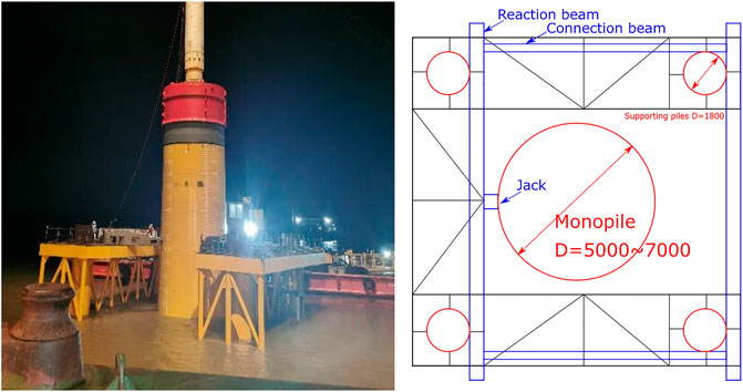
The study object, the A25 monopile foundation of a Vietnamese project, was focused. The monopile was manufactured with a diameter of 5.5 m, a length of 54 m (embedded depth of 41 m), and a thickness of 50–70 mm. Figure 1 shows the installation of the monopile by using an auxiliary installation platform onsite and the layout of the pile foundations. The auxiliary installation platform is composed of the main platform, four supporting piles with a diameter of 1.8 m, a lifting system, and a pile holding system, and is capable of installing a monopile with a diameter of 5–7 m. The monopile during the installation can be adjusted in the horizontal multidirections by using the hydraulic cylinder on the main platform.
The installation of the large-diameter monopile is composed of the GPS positioning, penetration of the supporting piles, installation of the main platform, large-diameter monopile driving, and finally removing the auxiliary installation platform. In this whole process, the supporting piles of the auxiliary installation platform will be penetrated and extracted, which will disturb the soil adjacent to the large-diameter monopile, and affect the performance of the monopile during the operation further. Therefore, it is necessary to study the influence of the installation on the performance of the monopile.
3 Numerical model in FLAC3D
3.1 Material properties
The geological conditions were verified depending on the piezocone penetration test (CPTU). Figure 2 represents the CPTU interpretation data at the location of the A25, i.e., the cone tip resistance qc, shaft friction fs, and the pore water pressure u2 at the tip. Table 1 lists the material properties of each sublayer based on the interpretation data according to the method by Robertson [14]. The elevation of the seabed is −3.0 m and is mainly composed of sand and clay. In particular, the organic clay in the shallow soil layer has a thickness of 11.3 m.
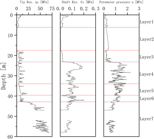
FIGURE 2. The profile of the cone penetration resistance, shaft resistance, and the pore water pressure.
3.2 Numerical model
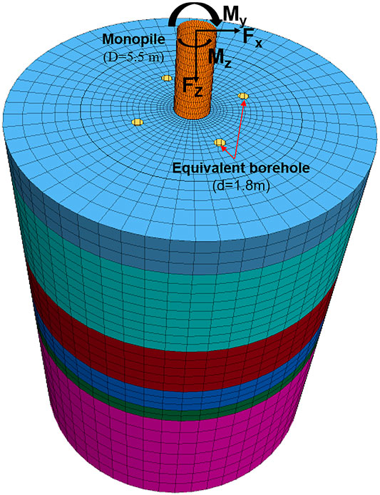
FLAC3D is an explicit finite volume program to study, numerically, the mechanical behavior of a continuous three-dimensional medium, and is widely applied in geotechnical engineering. Figure 3 describes the 3D numerical model of the A25 monopile foundation in the Vietnamese project, in which the soil is represented by the liner elements and the large-diameter monopile by the beam elements. The yellow boreholes can equivalently simulate the penetration and extraction of the supporting piles. The Mohr–Coulomb model is employed to describe the soil behavior, and all material properties from the CPTU interpretation data are listed in Table 2. It is suggested by the documentation of FLAC3D that the coefficient of the lateral earth pressure can be estimated onsite or by the equation K0 = ν/(1−ν), in which ν is the Poisson ratio. The K0 of sand can be particularly estimated by 1-sinφ´. Bolton represented that the dilation angle of sand was φ′-30°, and the dilation angle of clay was zero [19].
The numerical simulation, which was carried out for analyzing the weak effect on the performance of the large-diameter monopile by the installation platform, was simplified using the equivalent boreholes according to the representations by the guidance notes on the geotechnical performance of spudcan foundations [12]. The disturbance zone by the penetration and extraction of the supporting piles of the installation platform is usually in the area with a diameter of 1.5D and 1.0D, which can be adopted as the diameter of the equivalent boreholes, in which D is the diameter of the supporting pile. In this case, D = 1.8 m.
The pile is assigned with an elastic modulus of 210 GPa and a Poisson ratio of 0.3. The large-diameter monopile is composed of the liner elements, which can model the normal-directed compressive and tensile interaction, and the shear-directed frictional interaction. Figure 4 demonstrates the normal- and shear-directional interface behavior of the liner elements, for which the normal and shear coupling stiffnesses kn/ks, the (residual) cohesion c, the friction angle φ, and the tensile strength t are required. Note that a gap between the liner elements and the medium is allowed. These soil behaviors can also be mathematically described by Eqs. 1–3. The parameters (c,φ) can be empirically adopted as 60%–80% of these values of the surrounding soil [17, 18]. In this case, c = 70%csoil, φ = 70%φsoil, and t = 0.
3.3 Load combinations
The large-diameter monopile in extreme conditions is subjected to the structural loads, wave loads, current load, and the self-weight (incl. the wind power generator and the monopile foundation). According to the design standard, different loads should be combined to figure out the most disadvantageous case for the serviceability limit state (SLS) and the ultimate limit state (ULS). The deformations of the monopile foundation at the top and the mudline are mainly focused in the SLS; and the bearing capacity, the stability, and the strength tolerance of the monopile are mainly focused in the ULS. The structural load listed in Table 2 is provided by the manufacturer. The wave load and the current load are determined based on the design high/low water table in the SLS as well as the extreme high/low water table for the 50-year return period in the ULS [15]. According to the Code of Hydrology for Harbor and Waterway [16], they can be determined by the Morison equations, as listed in Table 3 Note that the structural loads are applied at the top of the monopile foundation, the wave load and current load are equivalently applied at the mudline.
3.4 Load pattern
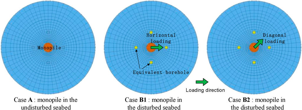
The locations of the four equivalent boreholes are represented in Figure 5. Two representative load patterns are selected for the following analyses, i.e., the horizontal loading (Case B1) and the diagonal loading (Case B2). For a quantitative comparison, the performance of the monopile in the undisturbed seabed is simulated as well. It is called Case A. The steps to simulate the performance of the monopile are:
i Balancing the earth pressure field.
ii Activating the large-diameter monopile.
iii Excavating the equivalent boreholes of the supporting piles.
iv Appling the combined loads.
v Extracting the data for analyses.
4 Results of numerical simulations
4.1 Sensitivity analyses
The bearing capacity of the monopile under the horizontal and vertical loading, as well as the bending moment, was analyzed using the numerical simulation in the program FLAC3D. The diameter of the monopile varied at 5, 6, and 7 m. Figure 6 illustrates the simulation results of the monopile with different diameters in different load patterns, note that the horizontal loading and diagonal loading for the monopile subjected to the vertical loads are identical.
The bearing capacity for the horizontal load and the bending moment are more critical than for the vertical loads. The load–displacement curves of the monopile under different loads are mostly hyperbolic shapes without a significant yielding point. Thus, it can be empirically recognized that the ultimate limit state is achieved when the horizontal displacement is achieved at 0.02D [10]. Table 4 lists the bearing capacity of the monopile determined at 0.02D of the horizontal displacement. It was found that the load–displacement curves were similar, and the diameter of the monopile affected significantly the lateral bearing capacity. The lateral bearing capacity increased with a larger diameter of the monopile. Case B1 was more critical than case B2, and the lateral bearing capacity in case B1 was reduced up to 7% in comparison with case A. The weak effect was reduced when the diameter increased. The lateral bearing capacity of the monopile would be overestimated when the weak effect was ignored. The bearing capacity for the bending moment was reduced up to 2.7% in comparison with case A, but the disturbed seabed barely affected the vertical bearing capacity.
4.2 Analyses in serviceability limit state and ultimate limit state
The performance of the large-diameter monopile at the location of A25 was analyzed in the SLS and ULS. The monopile in the undisturbed seabed for comparison was simulated as well. This work can provide some suggestions for the monopile design.
4.2.1 Serviceability limit state
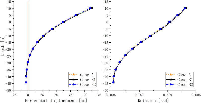
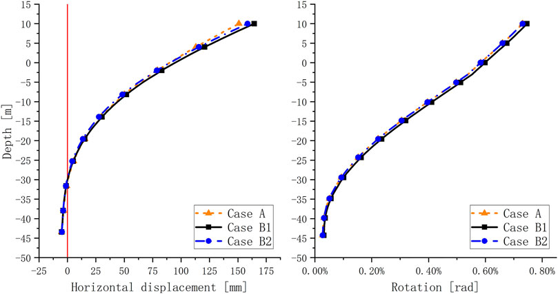
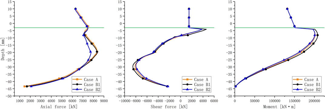
Figures 7 and 8 represent the deformation characteristics and internal forces along with the length of the monopile. It was found that the distributions along with the length of the monopile were similar. Table 5 summarizes the maximum deformations and the maximum internal forces of the monopile in the disturbed seabed. The maximum horizontal displacement and the maximum rotation at the mudline were 51.8 mm and 3.85‰ (≈0.22 grad), respectively, which were increased by about 5.13% and 2.12% in comparison with the monopile in the undisturbed seabed. The deformations of the monopile in the disturbed and undisturbed seabed satisfied the serviceability constraints. The maximum axial force, shear force, and moment of the monopile in the disturbed seabed were 8,370.8, 8,531.3, and 207,986.5 kN m, which were increased by about 7.79%, 6.81%, and 3.49%, respectively.
4.2.2 Ultimate limit state
Figures 9 and 10 represent the deformation characteristics and internal forces along with the length of the monopile in ULS. Table 6 summarizes the maximum deformations and the maximum internal forces of the monopile in the disturbed seabed. The curve shapes of the deformations and the internal forces in the ULS were similar to those in SLS, but the values were increased significantly. The deformations of case B1 in ULS were the largest, the deformations of case A were the smallest. The monopile under horizontal loading in the disturbed seabed deformed with a maximum horizontal displacement of 77.43 mm and a maximum rotation of 5.53‰, which were increased approximately about 4.56% and 2.79%, respectively. Similarly, the internal forces of the monopile in the disturbed seabed were increased significantly. The maximum axial force, shear force, and moment were 8,370.8, 8,531.3, and 207,986.5 kN m, which were increased about 7.79%, 6.81%, and 3.49%, respectively.
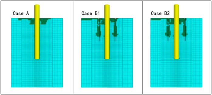
Figure 11 describes the plastic zone of the surrounding soil under different loading patterns. In case A, the shallow soil up to a depth of 7 m yielded mainly. The yielding area was increased in cases B1 and B2 after the disturbances by the penetration and extraction of the supporting piles for the installation platform. However, the stress rearrangement of the surrounding soil did not affect significantly the pile–soil interaction due to sufficient distance between the equivalent boreholes and the large-diameter monopile. Thus, the disturbance by the installation platform limitedly affected the performance of the monopile.
5 Conclusion
The installation platform often disturbs the surrounding seabed adjacent to the monopile in the phase of the installation, which can affect the performance of the monopile during the operation. It was analyzed depending on the A25 monopile foundation of a Vietnamese project for summarizing the effects of the penetration and extraction of the supporting piles on the performance of the large-diameter monopile. It was observed that, due to the disturbed seabed, the lateral bearing capacity was significantly reduced by up to 7%, while the horizontal displacement is achieved at 0.02D. In the serviceability limit state (SLS), the maximum horizontal displacement and the maximum rotation at the mudline were increased by about 5.13% and 2.12%. In the ultimate limit state (ULS), the internal force was increased up to 7.79%. The current study is limited to a large-diameter monopile under monotonic loading on site. A cyclic correction for this weak effect by the installation platform is the next step in future works.
Data Availability Statement
The raw data supporting the conclusion of this article will be made available by the authors, without undue reservation.
Author Contributions
CF, HB, and GP provided the CPTU data and performed some tasks of simulation in this study. GX performed a portion of the simulations and wrote the text with CF under the technical notes by ZY and CW. ZY helped during the simulation and gave some comments for building the numerical model.
Conflict of Interest
CF, HB, and GP were employed by the company “PowerChina Huadong Engineering Corporation Limited” and GX, ZY, and CW were employed by the company “PowerChina Huadong Engineering Corporation Limited” and “HydroChina Itasca R&D Center.”
Publisher’s Note
All claims expressed in this article are solely those of the authors and do not necessarily represent those of their affiliated organizations, or those of the publisher, the editors, and the reviewers. Any product that may be evaluated in this article, or claim that may be made by its manufacturer, is not guaranteed or endorsed by the publisher.
References
1. Negro V, López-Gutiérrez J-S, Esteban MD, Alberdi P, Imaz M, Serraclara J-M. Monopiles in Offshore Wind: Preliminary Estimate of Main Dimensions. Ocean Eng (2017) 133(MAR.15):253–61. doi:10.1016/j.oceaneng.2017.02.011
2.DNVGL-ST-0126. Support Structures for Wind Turbines[S] (2016). Available at: https://rules.dnv.com/docs/pdf/DNV/ST/2018-07/DNVGL-ST-0126.pdf (Accessed November, 2021).
3.JTJ 254-1998. Code for Pile Foundation of Harbor Engineering[S] (1998). Ministry of Transport of the People's Republic of China.
4.American Petroleum Institute. Geotechnical and Foundation Design considerations[S]. Us: American Petroleum Institute (2014). ANSI/API recommended practice 2 GEO first edition.
5. Zhang L, Gong X, Li R, Jiao D. Elastoplastic Solution of Deflections and Inner Forces for Slightly Inclined Single Pile Subjected to Combined Vertical and Lateral Loads[J]. J Cent South Univ (Science Technology) (2017) 048(007):1901–7. doi:10.11817/j.issn.1672-7207.2017.07.029
6. Xing K, Wu W, Zhang S, Liu H. Analysis Method for Bearing Capacity of Large Diameter Pile Foundation Based on Modified Strain Wedge Model[J]. Saf Environ Eng (2020) 27(No.12903):204–11.
7. Liu R, Zhou L, Lian J-j., Ding H-y. Behavior of Monopile Foundations for Offshore Wind Farms in Sand. J Waterway, Port, Coastal, Ocean Eng (2016) 142(1):04015010. doi:10.1061/(asce)ww.1943-5460.0000312
8. Zhang Q, Zhang Y, Lin H, Feng L. Numerical Investigation on Bearing Capacity of OWT Foundation with Large Diameter Monopile under Seismic Load. Appl Ocean Res (2021) 108:102518. doi:10.1016/j.apor.2020.102518
9. Li F, Tian P, Wang L, Chen M. Investigation on Lateral Bearing Capacity of Monopile under Combined Vertical-Lateral Loads and Scouring Condition. Mar Georesources Geotechnology (2021) 39(4):505–14. doi:10.1080/1064119x.2020.1719562
10. Kong D, Liu Y, Deng M, et al. Analysis of Influencing Factors of Monopile Foundation-Soil Interaction Characteristics for Offshore Wind Power[J]. Ocean Eng 39(1):12. doi:10.1016/j.apor.2020.102106
11. Zou T, Liu X. Verticality Control of Oversize Steel Pipe Pile Sinking of Offshore Wind Power[J]. China Harbour Eng (2018) 35(S1):4–9.
12.ABS. ABS 246 CORR-2018, Guidance Notes on Geotechnical Performance of Spudcan foundations[S]. United States: ABS (2018).
13. Kellezi L, Sundararajan S. Spudcan-Soil-Jacket Pile Group Foundation Interaction during Jack-Up Rig Installation and Removal. In: 14th International Jack-up Conference; November 2021; Copenhagen, Denmark (2013).
14. Robertson PK. Interpretation of Cone Penetration Tests-A Unified Approach [J]. Can Geotechnical Journa (2009) 46(46):1337–55. doi:10.1139/t09-065
15.NB/T 10105-2018. NB/T 10105-2018, Code for Design of Wind Turbine Foundations for Offshore Wind Power Projects[S] (2018). Available at: https://www.chinesestandard.net/PDF/English.aspx/NBT10105-2018 (Accessed November, 2021).
16.JTS 145-2015. JTS 145-2015, Code of Hydrology for Harbour and Waterway[S]. (2015). Available at: https://www.chinesestandard.net/PDF/English.aspx/JTS145-2015 (Accessed November, 2021).
17.Itasca Consulting Group, Inc. FLAC3D — Fast Lagrangian Analysis of Continua in Three Dimensions. Minneapolis: Itasca (2020). Version 7.0.
18. Sørensen SPH, Møller M, Brødbæk KT, Ibsen LB. Evaluation of Load-Displacement Relationships for Non-slender Monopiles in Sand[J]. Faits De Langues (2009) 5(9):193–200. doi:10.3406/flang.1997.1155
Keywords: monopile with large diameter, bearing capacity, installation disturbance, numerical simulation, FLAC3D
Citation: Fabo C, Ben H, Peng G, Xiangming G, Yong Z and Weijiang C (2022) Effect of Installation Platform on Bearing Capacity of an Offshore Monopile Foundation. Front. Phys. 9:809581. doi: 10.3389/fphy.2021.809581
Received: 05 November 2021; Accepted: 02 December 2021;
Published: 12 January 2022.
Edited by:
Chun Zhu, Hohai University, ChinaReviewed by:
Jinzhong Liu, Shandong University of Science and Technology, ChinaZequn Hong, China University of Mining and Technology, China
Copyright © 2022 Fabo, Ben, Peng, Xiangming, Yong and Weijiang. This is an open-access article distributed under the terms of the Creative Commons Attribution License (CC BY). The use, distribution or reproduction in other forums is permitted, provided the original author(s) and the copyright owner(s) are credited and that the original publication in this journal is cited, in accordance with accepted academic practice. No use, distribution or reproduction is permitted which does not comply with these terms.
*Correspondence: Ge Xiangming, Z2VfeG1AaGRlYy5jb20=
 Chen Fabo1
 Ge Xiangming