
94% of researchers rate our articles as excellent or good
Learn more about the work of our research integrity team to safeguard the quality of each article we publish.
Find out more
REVIEW article
Front. Phys. , 07 January 2022
Sec. Low-Temperature Plasma Physics
Volume 9 - 2021 | https://doi.org/10.3389/fphy.2021.808971
The First Helicon Plasma Physics and Applications Workshop was held on September 23−24, 2021, through Zoom Cloud Meeting, instead of in an on-site gathering, due to the COVID-19 pandemic. It was convened by Rod Boswell (IOC) and Guangnan Luo (LOC), and organised by Lei Chang’s group. The workshop attracted 110 registrations and
Helicon plasma has been attracting great interests since its first production in 1968 [1, 2]. Because of its remarkable ionisation rate (100% in core region), high density (1018 − 1020 m−3), and electrodeless feature, it finds various applications including material processing, space propulsion, magnetic fusion, and fundamental plasma physics [3–13]. There are 840 and 2,394 records, respectively, with “helicon plasma” in the title and topic from the Web of Science. However, to our best knowledge, the “Mini-conference on helicon plasma sources” in 2008 is the only meeting until now held particularly for this field [14]. Initially proposed to commemorate the 50th anniversary of the first publication of helicon plasma (1970−2020) but delayed by the COVID-19 pandemic, the First Helicon Plasma Physics and Applications Workshop (referred as HPPA-2021 hereafter) was organised on September 23−24, 2021, by the Institute of Plasma Physics, HFIPS, Chinese Academy of Sciences. It aims to establish a professional and regular meeting for academic exchange, to promote the physics understanding and application development of helicon plasma, as well as the collaborations between research groups. The HPPA-2021 attracted 110 registrations and
Rod Boswell gave a review presentation on the history, mechanism, and future of helicon plasma. The dispersion relation, E-H-W transition, wave damping, antenna excitation, and blue-core mode during helicon discharge were introduced in detail. The relationship between plasma density and input power can be approximated as:

FIGURE 1. Illustration of the interaction between electrons and helicon wave in phase space (A) and comparison between numerical and experimental electron densities (B). Reproduced from [15], with the permission of AIP Publishing.
Earl Scime shared insight into the processes responsible for the creation and heating of helicon plasma through the coupling of RF energy into ions and electrons. [17–19]. He presented the measurements of ion and electron velocity distribution functions in helicon sources as a function of antenna frequency, magnetic field strength, operating pressure, and radial location. It is observed that clear resonances in ion and electron energisation take place at specific, but different, antenna frequencies and magnetic field strengths. Figure 2 illustrates the dependence of electron temperature, plasma density, and ion temperature on antenna frequency and magnetic field strength [17]. Notably, the particle energisation is also anisotropic and depends on the direction of the applied magnetic field [20, 21]. Moreover, it is suggested that edge electron heating, which would be expected for slow wave damping, creates an energetic electron population that travels downstream along the expanding magnetic field and sets up an ambipolar potential that then accelerates the ions out of the plasma core in low pressure helicon plasmas, forming a ring of fast electrons around an ion beam in the core. These measurements of deep physics provide an interesting and inspiring picture of helicon ionisation procedure.
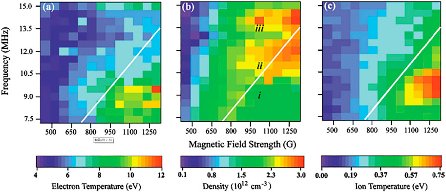
FIGURE 2. Variations of electron temperature (A), plasma density (B), and ion temperature (C) with antenna frequency and magnetic field strength. Reproduced from [17], with the permission of APS Publishing.
Juan Caneses reported plasma-induced surface heat fluxes incident on the helicon window during high power operation (60−150 kW net power), oriented for the design of the upcoming material plasma exposure experiment (MPEX) [22–24]. He introduced the infrared imaging system and associated physics models for the extraction of surface heat fluxes. The control of plasma strike point via magnetic flux mapping and dedicated limiters performs effectively in terms of reducing heat loads on the dielectric window. Figure 3 shows the employed flux mapping scenarios and corresponding magnetic field strength profiles. It is claimed that the flux mapping must create a gap between the plasma and the dielectric window of at least the plasma radial decay length. This scheme could reduce the power lost to the dielectric window by 33% if extrapolated to 200 kW. These findings are of particular interests for the design of high-power helicon plasma sources operating in steady state, e.g., linear plasma-material interaction (PMI) simulators, electric thrusters, and negative ion sources. Moreover, the presented infrared imaging system with heat extraction model could find applications in other fields as well.
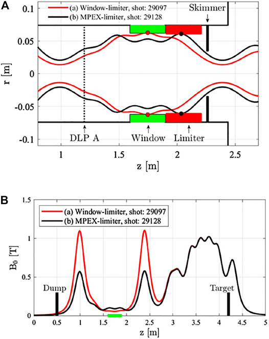
FIGURE 3. Illustration of two different flux mapping scenarios in Proto-MPEX (A) and the corresponding magnetic field strength profiles (B). Reproduced from [24], with the permission of IOP Publishing.
Lei Chang first reviewed the five popular hypotheses: (1) collisional damping [25], (2) Landau damping [25, 26], (3) electrostatic ion-sound instability/turbulence [27–29], (4) helicon-TG (Trivelpiece–Gould) conversion [30], and (5) radially localized helicon (surface-type) [31], regarding the ionisation mechanism of helicon plasma. It is commented that (a-c) are generic phenomena for plasma discharge and insufficient to support the remarkable ionisation rate and high density of helicon sources, and more attention should be paid to (d-e) which involves the critical parameter of confining magnetic field that promotes the density jump from inductively coupled plasma to helicon mode; further, (4) and (5) rely on density magnitude and density gradient, respectively, and optimum discharge may be achieved when the required density magnitude comes across with the largest density gradient at the same location. Then, the sign (positive or negative) and zero-crossing position of second-order density gradient are shown to effect the power absorption profile significantly, consistent with (5) [32–34]. Moreover, it is suggested that the power deposition profile could be shaped by designing the antenna of particular geometry to excite the required axial current distribution, considering their resemblance. Interestingly, the spectral gap and gap eigenmode (Figure 4 shows an example) of helicon wave propagating in a periodic structure with local defect are also introduced [35]. This talk suggests new directions for fundamental helicon research and antenna optimisation in experiment.
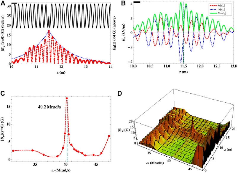
FIGURE 4. Gap eigenmode of helicon wave propagating in a periodic structure with local defect. Reproduced from [35], with the permission of IOP Publishing. (A) Longitudinal profiles of the static magnetic field (solid line) and the rf magnetic field on axis (dots), together with the theoretically calculated envelope (dotted line); (B) longitudinal profile of the rf electric field (on-axis) (vertical dot-dashed line marks the defect location, and solid horizontal bar marks the antenna); (C) resonance in the dependence of the on-axis amplitude of the rf magnetic field on driving frequency at the location of the defect; (D) 3D plot of the on-axis wave field strength.
Shogo Isayama presented a self-consistent fluid model. It includes neutral dynamics and could certify several important temporal behaviors of power absorption, flux balance, and density jumps in high-density helicon plasma. The computed results agree well with experimental data [36, 37]. Figure 5 shows the spatial profiles of electron density, electron temperature, and power absorption at three subsequent times: 12 μs, 30 μs, and 122 μs. It is claimed that there exists a cutoff density above which helicon wave becomes prominent and strong coupling between helicon and TG modes yield more power deposition towards the core. The dynamic behaviors of helicon discharge involving the effect of neutral dynamics were discussed in detail. It shows a clear procedure of equilibrium establishment and helps the understanding of helicon-TG conversion.
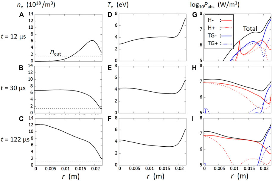
FIGURE 5. Computed profiles of electron density (A–C), electron temperature (D–F) and power absorption (G–I) at t = 12 μs, t = 30 μs, and t = 122 μs. Reproduced from [36], with the permission of AIP Publishing.
Mingyang Wu introduced a numerical study on the mode transition and discharge process of helicon plasma [38]. Simulations are conducted through a recently developed code, i.e., Peking university helicon discharge (PHD). The computed physics include ionisation process, particle transport, power deposition, and mode transition. It is claimed that large-amplitude standing helicon waves are responsible for the mode transitions during helicon discharge, similar to the concept of a resonant cavity for laser generation. Moreover, this resonance theory could explain several key questions regarding helicon plasma and guide plasma production in experiment. More interesting and deep findings are expected from the PHD simulations in the future.
Yunju Chang studied the temporal evolution of helicon discharge based on drift-diffusion equations [39]. It is found that electron density and temperature arrive steady-state around 100 μs and 1.5 μs, respectively, while electric and magnetic wave fields arrive steady-state around 2 μs. The steady-state electron density and power absorption profiles exhibit consistency with previous experiments and computations, validating the presented work. Parameter studies illustrate that high background pressure, confining magnetic field, and RF power are beneficial to obtaining high-density helicon plasma, especially the blue-core mode, while the driving frequency has little effect. Although these COMSOL Multiphysics simulations show interesting results, future effort may be devoted to PIC simulations to reveal more details about helicon plasma establishment.
Ruilin Cui talked about the experimental results of discharge characteristics and heating mechanism of argon helicon plasma in different wave modes from Langmuir probe, magnetic probe, and local optical emission spectroscopy (LOES) [40]. It is shown that there exist three or four distinct wave modes (i.e., number of half-wavelengths along the axial direction mz = 1, 3, 5, or 7) under different operating conditions. The lowest wave mode has a travelling wave structure of smaller wavelength from the antenna center to the downstream, while the other wave modes are all characterized by complex wave structure of standing wave in the downstream of the antenna and traveling wave in the upstream, respectively. Moreover, the azimuthal electron heating of standing wave is dominant in most wave modes except the lowest wave mode for which the wave-electron coupling of traveling wave dominates. The existence of higher distinct wave modes looks very interesting, together with the different features of wave propagation, although their underlying physics may need further exploration in the next steps.
Tianliang Zhang showed the effects of neutral depletion on the blue-core helicon discharges of nitrogen (N2) and oxygen (O2) [41]. For N2, the main species in the core are N2,
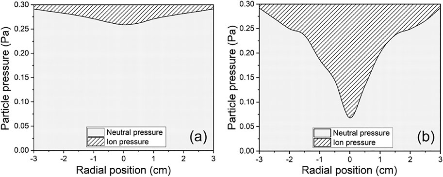
FIGURE 6. Radial profiles of ion pressure and neutral pressure: (A) without blue core, (B) with blue core. Reproduced from [41], with the permission of AIP Publishing.
Hao Liu described a planar helicon plasma source with four-ring antenna for the linear experimental advanced device (LEAD) (Figure 7) [42, 43]. The diameter of the largest ring is 0.32 m. A special feature of the source lies in that the antenna is placed over the cross-section at one end of the vacuum chamber. RF power is fed from the antenna into the chamber through a quartz window of diameter 0.34 m. It is reported that low power threshold of 150 W for H-W transition has been experimentally confirmed. The high performance of this large-area helicon source is also demonstrated by the plasma density of
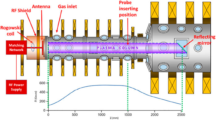
FIGURE 7. LEAD (linear experimental advanced device). Reproduced from [43], with the permission of IOP Publishing.
Xin Yang delivered a talk on a recently designed and constructed device, i.e., physics and thruster oriented helicon research (PANTHER) [44, 45], to study the fundamental physics of helicon plasma with potential applications to space propulsion. One of the special features is that the antenna wrapping around quartz tube is immersed in a vacuum to simulate the space environment. The magnetic field produced by three sets of liquid-cooled solenoid coils is highly flexible with strength up to 0.18 T. The downstream plasma density, light emission, and plasma impedance are characterised in detail. Dynamic transitions from regular helicon mode to blue and blue-core modes are also observed and measured by argon-ion line (Ar II 480 nm) emission. It is shown that the input power and magnetic field strength are key factors determining the blue-core formation, while higher magnetic field and lower pressure result in better power coupling during helicon discharge. The vacuum environment outside quartz tube is indeed necessary to study problems such as heat for a helicon source in space.
Chenyao Jin narrated the development of helicon detachment test source (Hi-DTS) constructed to investigate the physical processes of sheath formation related to divertor detachment in fusion devices. Two sets of Langmuir probes and a LIF diagnostic system are installed to explore the discharge characteristics and mode transitions. The effects of neutral pressure, magnetic field strength, and input power are measured and consistent with previous studies. The diagnostics of Hi-DTS could provide comprehensive spatial profiles of electron and ion parameter distributions. It is shown that the electron density and electron temperature can be up to
Chishung Yip revisited the known fast sweep Langmuir probe techniques in a uniform, quiescent multi-dipole confined hot cathode discharge with two operation scenarios: the probe sweeping frequency is much lower or greater than the ion plasma frequency. Distortions of I-V traces at high frequencies are not observed in the degree previously claimed to be the ion-motion limitation effect, unless that shunt resistance is sufficiently high. Comparison between high-speed dual Langmuir probe and single probe demonstrates that the capacitive response could be removed through subtracting a load line for the single probe, which then works effectively as the high-speed dual Langmuir probe. However, the high-speed dual Langmuir probe remains advantageous for better recovery of weak current signal in low-density plasmas. These deep comprehensions and findings offer inspiring knowledge for the usage of Langmuir probe.
Yong Wang designed a high-resolution laser Thomson scattering (LTS) system to diagnose low-pressure plasmas. A homemade triple gratings spectrometer (TGS) has been elaborated to physically block strong stray light and accurately measure electron temperature (Te) and electron density (ne). The spectral resolution can be up to 0.07 nm in full-width-half-maximum at 532 nm, allowing the measurement of Te as low as 0.1 eV. The limit of ne detection is around 1.0 × 10¹⁷ m−3, benefiting from the great suppression of stray light. There is a software specially designed to automatically process the complex LTS spectra distorted by TGS and to determine Te and ne in real time. This LTS system has been employed successfully for cascaded arc plasma [46, 47], nanosecond pulse discharge plasma [48], and RF plasma (Figure 8 shows the experimental setup) [49]. The employment of LTS system to precisely measure the temperature of helicon plasma is also possible, exciting, and expected in the ongoing work.
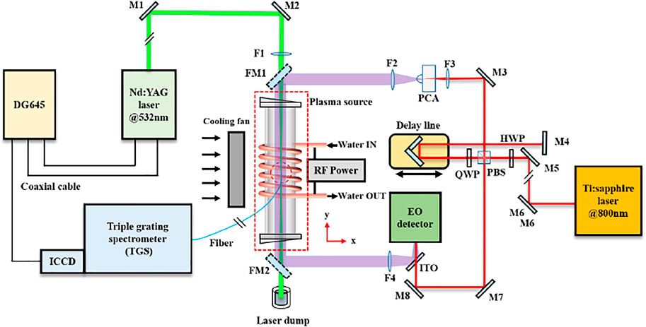
FIGURE 8. Experimental setup showing laser Thomson scattering (LTS) employed for RF plasma diagnostics. Reproduced from [49], with the permission of IOP Publishing.
Haibao Zhang employed retarding field energy analyzer (RFEA) to study the ion energy evolution in argon helicon plasma. The ion density and ion energy are measured in the plasmas excited by loop and right-helical antennas, respectively. The influence of discharge parameters, i.e., input RF power and background pressure, on the ion energy evolution is explored. It shows that for E and H modes the peak of ion energy increases with RF power, whereas for W mode the peak drops with power, and it drops again when the discharge further transits to blue-core mode. The change of ion energy during mode transitions is consistent with plasma density, although the trend is opposite. Detailed modelling is required to show the underlying physics, which may be underway.
Shunjiro Shinohara overviewed the studies on various-sized helicon plasma sources and their application to plasma thrusters under the helicon electrodeless advanced thruster (HEAT) project [50]. The characteristics of very large (up to 0.74 m in diameter and 4.86 m in axial length [51]) or small (from 0.02 m to 0.000 5 m in diameter [52, 53]) sources driven by a broad range of frequency (7−435 MHz) are presented, together with their plasma thrust performance. These sources exhibit excellent performance in terms of particle production efficiency, and can be utilised to study electrostatic drift instabilities with high-pressure gradient and high-β (β ∼ 1) physics. Electrodeless acceleration methods of rotating magnetic field [54, 55] and m = 0 half cycle [56] are also introduced. Figure 9 displays the schematics. Emphasis is given particularly to the importance of diagnostics, including laser induced fluorescence, tomography using high-speed camera with interference filters (involving a collisional radiative model to deduce electron temperature and density [57]), and various thrust stands. These innovative explorations on the size limit of helicon plasma source and electrodeless acceleration schemes are very impressive and may inspire new applications.

FIGURE 9. Electrodeless acceleration schemes: (A) rotating magnetic field, reproduced from [54], with the permission of JSPF; (B) m = 0 half cycle, reproduced from [56], with the permission of IEEE Publishing.
Kazunori Takahashi clarified the thrust generation and loss processes by the direct thrust measurement and individual measurements of the force exerted to magnetic nozzle via electron diamagnetic Lorentz force and the force exerted to radial wall [58–61]. Figure 10 shows the measured plasma pressure profile and particle dynamics relating to the loss of axial momentum [62]. It is claimed that the propulsive magnetic nozzle (increasing thrust) is essentially caused by the diamagnetism of plasma flow (decreasing axial magnetic field and diverging magnetic nozzle), and the plasma flow state stretching magnetic nozzle has not been observed in laboratory experiments. The stretch of magnetic nozzle occurs at the axial location of Alfvén Mach number less than unity, with the diamagnetic momentum gain maintained near the thruster exit [63]. The presented model qualitatively explains this stretch of magnetic nozzle, while the change of magnetic field strength is a few percent of the applied magnetic field. Moreover, the pure interaction between electron gas and magnetic nozzle is studied based on a specially constructed experiment, by removing the electric field from the system [64]. Electron energy probability functions are measured precisely, revealing the adiabatic expansion of electron gas without electric field [65, 66]. The status of thruster performance and new application of plasma thrusters to active space debris removal are also introduced. These detailed studies on the interaction between plasma and magnetic nozzle, with respect to thrust optimisation, show very deep physics and inspiring findings.
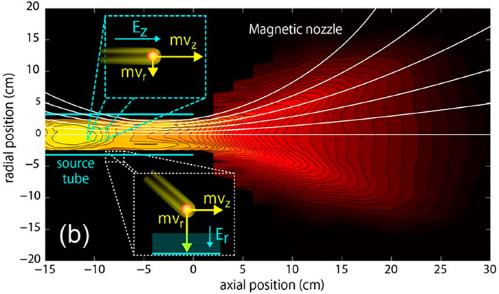
FIGURE 10. The measured plasma pressure profile and particle dynamics relating to the loss of axial momentum. Reproduced from [62]. Credit: Kazunori Takahashi.
Kuan Qiao proposed a confining criterion for plasma plume in magnetic nozzle via the theory of adiabatic loss separation. It is a dimensionless parameter (Q = rci∇B/B0) and can visually reflect the strength of magnetic field confinement and the behavior of plasma in the magnetic nozzle. Combined with COMSOL Multiphysics simulations, experiments are carried out to explore the effects of magnetic field strength and gradient on the plasma confining effectiveness and the relationship with the confining criterion through adjusting coil current. The validity of this confining criterion may need further experimental confirmation, which will be possibly seen in the upcoming publication.
Zhen Wang exhibited a miniaturized helicon plasma thruster of mN class. The inner diameter of discharge cavity is in scale of mm. Successful ignition in a vacuum environment is achieved based on a suitable RF source with customized matching box. A thrust frame (suspended target type) is designed to measure the thrust indirectly. The elastic element of connection between movable and fixed frames uses pivot. Polycarbonate serves as the target surface material. Closed-loop control is realized through a PID (proportional, integral, derivative) control circuit. Calibration of the thruster shows good linearity, which paves the way for practical thrust measurement. This is perhaps the smallest helicon source developed in China and most close to space applications.
Tianyuan Huang researched wall conditioning and surface treating based on high magnetic field helicon experiment (HMHX) [67]. The HMHX can generate steady-state high-density plasma with relatively low electron temperature, a promising candidate to simulate the edge plasma in fusion reactors and to study PMI problems including impurity transport, sputtering, co-deposition, fuel recycling, and retention. Its magnetic field compatibility and wide range of excitation frequency are technically validated on the experimental advanced superconducting tokamak (EAST), through self-designed helicon antenna modules [68]. Figure 11 shows the experimental setup and typical image for toroidal field strength of 0.5 T, RF power of 20 kW, and He pressure of 0.27 Pa. Moreover, through HMHX, tungsten nitride and carbon-based (vertical graphene nanosheets and multi-wall carbon nanotube arrays) functional films are synthesized respectively on silicon substrate by physical sputtering and chemical vapor deposition techniques with high deposition rate at room-temperature [69–71]. This work represents the first application of helicon plasma for Tokamak wall conditioning in China, an interesting exploration of great practical value.

FIGURE 11. Wall conditioning on EAST via helicon discharge: (A) experimental setup, (B) typical image. Reproduced from [68], with the permission of IEEE Publishing.
Jingchun Li investigated helicon wave heating and current drive in toroidal plasmas by the ray-tracing code GENRAY [72–74]. It is found that increasing poloidal launch angle does not vary the absorption rate of helicon wave, but rather moves the peak of wave absorption towards the core of plasma. Frequency in range of 460−480 MHz shows little effect on wave absorption. Variations of the peak position and magnitude of wave power deposition with launched parallel refractive index are also presented, for low and high plasma parameters, respectively. The driving current increases with temperature but oppositely with density in the core. Ohmic current does not change the helicon current drive efficiency significantly, but moves the driven current toward the core and results in narrowed width of current profile. Figure 12 illustrates the helicon wave trajectories and profiles of driven current for different plasma parameters. This work serves as a reference and theoretical basis for the experimental implementation of helicon wave heating and current drive in tokamaks such as HL-2M and EAST.
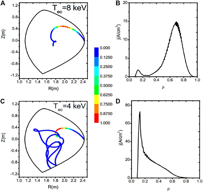
FIGURE 12. Helicon wave trajectories and profiles of driven current for different plasma parameters: (A) and (B), nec = 6.4 × 10¹⁹ m−3 and Tec = 8 keV; (C) and (D), nec = 4.0 × 10¹⁹ m−3 and Tec = 4 keV. Reproduced from [74], with the permission of IOP Publishing.
There are also discussions on the ionisation mechanism and blue-core phenomena of helicon plasma over the chatline of Zoom Cloud Meeting. We summarise them below by person so that the presented opinions are traceable.
Rod Boswell:
• In my PhD thesis, the collisionless damping of electrons was shown to be ineffective for heating. However, Bert Ellingboe showed by fast spectroscopy that wave particle trapping is clearly responsible for the excess ionisation [75]. Actually, the same thing was shown experimentally by Hong-Young Chang at KAIST [76, 77].
• Regarding the edge heating, this will occur simply through the skin depth (evanescent wave) of the RF antenna. If you measure away from the antenna there is no edge heating, just the blue core. But as I mentioned, the helicon needs to do effective work on the electrons and this is best seen when the wave accelerates electrons having an energy just below the ionisation energy to just above the ionisation energy. Faster and slower waves will still interact with the electrons and can be used for current drive but they do not produce the sudden jump to the blue mode in argon.
• Our last measurements on the WOMBAT (waves on magnetised beams and turbulence) [78] strongly suggested that the long blue column extending 1.5 m from the source is produced by fast electrons coming from the source, which generates local ionisation [15, 16].
Xuan Sun:
• Several years ago, we had an antenna on one end of a mirror machine (10 m in length), and we successfully obtained blue core in the central cell of the mirror. The formed blue core is at least 7 m in length. At that time, we believed that it was the wave to cause ionisation. This made sense when we measured the axial density profile and the time delay of plasma generation from central cell to antenna.
• The helicon plasma was used to fill up the chamber. The blue core could be 10 m long from one end to the other end of machine. Later, we found that it could be the longest blue core observed in experiment. Unfortunately, we terminated and didn’t really study it. The input RF power was 2 kW and the working gas was hydrogen.
Saikat Thakur:
• I concur with Rod Boswell. We also found fast electrons in the blue-core mode. On the CSDX (controlled shear decorrelation experiment) device [79], we got blue cores of about 2 m in length and
Lei Chang:
• Ellingboe’s paper shows similar phase between energetic electron current and electron density [75], but the fraction of contribution is not shown. Is it possible to have other contributions besides wave-trapped energetic electrons?
• It is indeed extraordinary to have such a long distance of blue-core column, and the electrons can bring energy far away from the source. Is this axial extension caused by standing eigenmode or any mysterious “remote confinement”?
• I am wondering what causes and confines such a long-distance plasma column (blue core). The magnetic field is diverging from the end to the mid-plane of magnetic mirror and from source to downstream so that cannot be the reason.
• Another thing I am curious about is the upper pressure limit for helicon discharge; this is important for air-breathing electric thruster. Could anyone please provide comments or information about it?
• For students, the following links may be useful, and I suggest they read early references as many as possible to save time instead of repeating too much others’ work.
– Helicons and Their Surface Modes, http://www.heliconrefs.com
– Helicon Plasma, http://legolas.ece.wisc.edu/helicon.php
To create a quiz show environment, we collected questions beforehand from the helicon community. The following questions are from students and answered by Rod Boswell.
• When was the exact time that you first succeeded in helicon discharge?
– In 1968, in the third year of my PhD. It was in a 0.05 m diameter tube and the central column was so intense it melted the top of the tube!
• How did you come to the idea of double-saddle antenna design?
– To get power into the centre of the magnetised column using the radial component of the m = 1 wave field.
• What is the biggest jump that you made based on previous studies?
– Showing the wave fields of the electromagnetic whistler and the resonance cones forming a TG mode using a small 0.01 m diameter antenna.
• What is the general requirement of a helicon antenna?
– To be broad band and to produce a radial magnetic field.
• Do you agree with the theory of helicon-TG conversion for ionisation?
– There is no theory of helicon-TG conversion and no experimental evidence.
• What is the biggest progress regarding helicon research since 1970?
– Making people believe the experimental results.
• What are your suggestions for young scientists in this field?
– Test everything.
• Is it practical to apply helicon double-layer thruster in the future?
– Under certain conditions, yes. Kazunori Takahashi has managed to get 50 mN!
• Is it possible to obtain another density jump beyond helicon?
– No, there are problems with ion pumping so with higher power you just get higher ionisation states, like in a Tokamak.
• How to study the high-β effect of blue-core helicon plasma?
– Pulsing. Check our paper [80].
The phrase “blue-core” has been used widely in helicon references for argon discharge in particular; however, it may be generalised to “bright-core” to cover the common physics for other working gases as well, such as helium and nitrogen. Along with the helicon-TG conversion and energetic electrons, this “bright-core” phenomenon also remains as a challenging topic, attracting great research interest. This special discharge mode could manifest the essential physics of helicon-TG conversion and collisionless wave-electron interaction. Hence, it deserves special attention from the helicon community. As suggested previously, the characteristics of “bright-core” could be decomposed spatially into radial electrostatic confinement, light emission in phase axially and azimuthal instabilities driven by radial pressure gradients, together with high-β effects, showing the directions for future research. From the perspective of applying “bright-core” plasma to space propulsion and fusion-related PMI simulation, which require high and stable particle flux, effort should be also given to the size enhancement (diameter and length) and precise establishment (routine and reliability) of “bright-core” formation.
Future research can be also devoted to the direct identification of TG mode in experiment, which is a missing part for the helicon-TG conversion although challenging because of very small wavelength. To optimise the helicon source, the helicon-TG conversion and surface-type hypotheses might be combined, as pointed earlier; the required density magnitude if it occurs at the location where the second-order density gradient vanishes may yield best power coupling and ionisation efficiency. A fully consistent model covering the ionisation procedure, power transmission, wave propagation, particle transport, evolutionary instabilities, and their dynamic feedbacks to the established equilibrium is important work, as well as the corresponding program. Regarding the applications, novel exploration is always desired. Additionally, it is felt from the workshop that although the development and applications of helicon sources progress quickly in China, the deep explorations on fundamental physics and original innovations on modelling, coding and diagnosing are relatively immature, compared with research groups overseas, which may be improved in the next decade.
This workshop was convened by RB (IOC) and GL (LOC) and organised by LC’s group. The manuscript was prepared by these three authors together.
The authors declare that the research was conducted in the absence of any commercial or financial relationships that could be construed as a potential conflict of interest.
All claims expressed in this article are solely those of the authors and do not necessarily represent those of their affiliated organizations, or those of the publisher, the editors, and the reviewers. Any product that may be evaluated in this article, or claim that may be made by its manufacturer, is not guaranteed or endorsed by the publisher.
The authors would like to thank sincerely the contributions from speakers and audiences. The citation words are phrased based on their abstracts, presentations, and the authors’ understanding. Due to limited space, however, not all the presentations are included but appreciated in the same way. Gratitude is also given to the permissions for reprinting figures. This workshop is supported by the Department of International Cooperation (HFIPS) and the Bureau of International Cooperation, Chinese Academy of Sciences.
1. Boswell RW. A Study of Waves in Gaseous Plasmas. [PhD thesis]. Adelaide: Flinders University of South Australia (1970).
2. Boswell RW. Plasma Production Using a Standing Helicon Wave. Phys Lett A (1970) 33(7):457–8. doi:10.1016/0375-9601(70)90606-7
3. Petri R, Henry D, Sadeghi N. Tungsten Etching Mechanisms in Low‐pressure SF6plasma. J Appl Phys (1992) 72(7):2644–51. doi:10.1063/1.351565
4. McKenzie DR, McFall WD, Sainty WG, Yin Y, Durandet A, Boswell RW. New Technology for PACVD. Surf Coat Techn (1996) 82(3):326–33. doi:10.1016/0257-8972(95)02776-9
5. Arefiev AV, Breizman BN. Theoretical Components of the Vasimr Plasma Propulsion Concept. Phys Plasmas (2004) 11(5):2942–9. doi:10.1063/1.1666328
6. Ziemba T, Carscadden J, Slough J, Prager J, Winglee R. High Power Helicon Thruster. In: 41st AIAA/ASME/SAE/ASEE Joint Propulsion Conference & Exhibit; 2005 Jul 10–13; Tucson, AZ (2005). doi:10.2514/6.2005-4119
7. Charles C. Plasmas for Spacecraft Propulsion. J Phys D: Appl Phys (2009) 42(16):163001. doi:10.1088/0022-3727/42/16/163001
8. Batishchev OV. Minihelicon Plasma Thruster. IEEE Trans Plasma Sci (2009) 37(8):1563–71. doi:10.1109/tps.2009.2023990
9. Loewenhardt P, Blackwell B, Boswell R, Conway G, Hamberger S. Plasma Production in a Toroidal Heliac by Helicon Waves. Phys Rev Lett (1991) 67(20):2792–4. doi:10.1103/physrevlett.67.2792
10. Hanna J, Watts C. Alfvén Wave Propagation in a Helicon Plasma. Phys Plasmas (2001) 8(9):4251–4. doi:10.1063/1.1386801
11. Petrzilka V, Tataronis JA. Non-resonant Currents Driven by Helicon Waves. Plasma Phys Control Fusion (1994) 36(6):1027–35. doi:10.1088/0741-3335/36/6/006
12. Zhu P, Boswell RW. Ar Ii Laser Generated by Landau Damping of Whistler Waves at the Lower Hybrid Frequency. Phys Rev Lett (1989) 63(26):2805–7. doi:10.1103/physrevlett.63.2805
14. Scime EE, Keesee AM, Boswell RW. Mini-conference on Helicon Plasma Sources. Phys Plasmas (2008) 15(5):058301. doi:10.1063/1.2844795
15. Degeling AW, Boswell RW. Modeling Ionization by Helicon Waves. Phys Plasmas (1997) 4(7):2748–55. doi:10.1063/1.872143
16. Degeling AW, Sheridan TE, Boswell RW. Model for Relaxation Oscillations in a Helicon Discharge. Phys Plasmas (1999) 6(5):1641–8. doi:10.1063/1.873419
17. Kline JL, Scime EE, Boivin RF, Keesee AM, Sun X, Mikhailenko VS. Rf Absorption and Ion Heating in Helicon Sources. Phys Rev Lett (2002) 88(19):195002. doi:10.1103/physrevlett.88.195002
18. Kline JL, Balkey MM, Keiter PA, Scime EE, Keesee AM, Sun X, et al. Ion Dynamics in Helicon Sources. Phys Plasmas (2003) 10(5):2127–35. doi:10.1063/1.1563260
19. Aguirre EM, Bodin R, Yin N, Good TN, Scime EE. Evidence for Electron Energization Accompanying Spontaneous Formation of Ion Acceleration Regions in Expanding Plasmas. Phys Plasmas (2020) 27(12):123501. doi:10.1063/5.0025523
20. Scime EE, Keesee AM, Spangler RS, Koepke ME, Teodorescu C, Reynolds EW. Evidence for thermal Anisotropy Effects on Shear Modified Ion Acoustic Instabilities. Phys Plasmas (2002) 9(10):4399–401. doi:10.1063/1.1505847
21. Scime EE, Keiter PA, Balkey MM, Kline JL, Sun X, Keesee AM, et al. The Hot hELicon eXperiment (HELIX) and the Large experiment on Instabilities and Anisotropy (LEIA). J Plasma Phys (2014) 81(1):345810103. doi:10.1017/s0022377814000890
22. Rapp J, Biewer TM, Bigelow TS, Caughman JBO, Duckworth RC, Ellis RJ, et al. The Development of the Material Plasma Exposure experiment. IEEE Trans Plasma Sci (2016) 44(12):3456–64. doi:10.1109/tps.2016.2628326
23. Rapp J, Lau C, Lumsdaine A, Beers CJ, Bigelow TS, Biewer TM, et al. The Materials Plasma Exposure eXperiment: Status of the Physics Basis Together with the Conceptual Design and Plans Forward. IEEE Trans Plasma Sci (2020) 48(6):1439–45. doi:10.1109/tps.2020.2970398
24. Caneses Marin JF, Beers CJ, Chakraborty Thakur S, Simmonds MJ, Goulding RH, Lau C, et al. Characterizing the Plasma-Induced thermal Loads on a 200 kW Light-Ion Helicon Plasma Source via Infra-red Thermography. Plasma Sourc Sci. Technol. (2021) 30(7):075022. doi:10.1088/1361-6595/abf814
25. Chen FF. Plasma Ionization by Helicon Waves. Plasma Phys Control Fusion (1991) 33(4):339–64. doi:10.1088/0741-3335/33/4/006
26. Chen FF, Blackwell DD. Upper Limit to Landau Damping in Helicon Discharges. Phys Rev Lett (1999) 82(13):2677–80. doi:10.1103/physrevlett.82.2677
27. Akhiezer AI, Mikhailenko VS, Stepanov KN. Ion-sound Parametric Turbulence and Anomalous Electron Heating with Application to Helicon Plasma Sources. Phys Lett A (1998) 245(1-2):117–22. doi:10.1016/s0375-9601(98)00437-x
28. Virko VF, Kirichenko GS, Shamrai KP. Parametric Ion-Acoustic Turbulence in a Helicon Discharge. Plasma Sourc Sci. Technol. (2003) 12(2):217–24. doi:10.1088/0963-0252/12/2/313
29. Lorenz B, Krämer M, Selenin VL, Aliev YM. Excitation of Short-Scale Fluctuations by Parametric Decay of Helicon Waves into Ion-Sound and Trivelpiece-Gould Waves. Plasma Sourc Sci. Technol. (2005) 14(3):623–35. doi:10.1088/0963-0252/14/3/027
30. Shamrai KP, Taranov VB. Volume and Surface Rf Power Absorption in a Helicon Plasma Source. Plasma Sourc Sci. Technol. (1996) 5(3):474–91. doi:10.1088/0963-0252/5/3/015
31. Breizman BN, Arefiev AV. Radially Localized Helicon Modes in Nonuniform Plasma. Phys Rev Lett (2000) 84(17):3863–6. doi:10.1103/physrevlett.84.3863
32. Chang L, Li Q, Zhang H, Li Y, Wu Y, Zhang B, et al. Effect of Radial Density Configuration on Wave Field and Energy Flow in Axially Uniform Helicon Plasma. Plasma Sci Technol (2016) 18(8):848–54. doi:10.1088/1009-0630/18/8/10
33. Chang L, Hu X, Gao L, Chen W, Wu X, Sun X, et al. Coupling of RF Antennas to Large Volume Helicon Plasma. AIP Adv (2018) 8(4):045016. doi:10.1063/1.5025510
34. Wang R, Chang L, Hu X, Ping L, Hu N, Wu X, et al. The Role of Second-Order Radial Density Gradient for Helicon Power Absorption. Contrib Plasma Phys (2019) 59(9):e201900032. doi:10.1002/ctpp.201900032
35. Chang L, Breizman BN, Hole MJ. Gap Eigenmode of Radially Localized Helicon Waves in a Periodic Structure. Plasma Phys Control Fusion (2013) 55(2):025003. doi:10.1088/0741-3335/55/2/025003
36. Isayama S, Shinohara S, Hada T, Chen SH. Underlying Competition Mechanisms in the Dynamic Profile Formation of High-Density Helicon Plasma. Phys Plasmas (2019) 26(2):023517. doi:10.1063/1.5063506
37. Isayama S, Shinohara S, Hada T, Chen SH. Spatio-temporal Behavior of Density Jumps and the Effect of Neutral Depletion in High-Density Helicon Plasma. Phys Plasmas (2019) 26(5):053504. doi:10.1063/1.5093920
38. Wu M, Xiao C, Liu Y, Yang X, Wang X, Tan C, et al. Effects of Magnetic Field on Electron Power Absorption in Helicon Fluid Simulation. Plasma Sci Technol (2021) 23(8):085002. doi:10.1088/2058-6272/ac0718
39. Chang YJ, Chang L, Yuan XG, Yang X, Xu Q, Wang Y, et al. Numerical Study on the Temporal Evolution of a Helicon Discharge. IEEE Trans Plasma Sci (2021) 49(11):3733–44. doi:10.1109/TPS.2021.3121396
40. Cui R, Han R, Yang K, Zhu W, Wang Y, Zhang Z, et al. Diagnosis of Helicon Plasma by Local OES. Plasma Sourc Sci Technol (2020) 29(1):015018. doi:10.1088/1361-6595/ab56dc
41. Zhang T, Cui R, Zhu W, Yuan Q, Ouyang J, Jiang K, et al. Influence of Neutral Depletion on Blue Core in Argon Helicon Plasma. Phys Plasmas (2021) 28(7):073505. doi:10.1063/5.0050180
42. Liu H, Yu Y, Wang ZH, Xu M, Che T, Zheng PF, et al. Design of Magnetic Configurations for the Linear Plasma Device LEAD. Fusion Eng Des (2019) 144:81–6. doi:10.1016/j.fusengdes.2019.04.060
43. Liu H, Shinohara S, Yu Y, Xu M, Zheng PF, Wang ZH, et al. A Large-Area Planar Helicon Plasma Source with a Multi-Ring Antenna on Linear Experimental Advanced Device (LEAD). J Inst (2020) 15(11):P11002. doi:10.1088/1748-0221/15/11/p11002
44. Yang X, Yuan XG, Chang L, Xu Q, Zhang LP, Chang YJ, et al. Development and Characterization of a Helicon Plasma Source under High Magnetic Field with Antenna Immersed in Vacuum. Plasma Sourc Sci Techn (2022). in preparation.
45. Chang L, Zhang LP, Yuan XG, Chang YJ, Zhang JH, Yang X, et al. Coupling between Multiple Antennas through a Plasma cylinder. IEEE Trans Plasma Sci (2021). Submited.
46. Wang Y, Li C, Shi J, Wu X, Ding H. Measurement of Electron Density and Electron Temperature of a Cascaded Arc Plasma Using Laser thomson Scattering Compared to an Optical Emission Spectroscopic Approach. Plasma Sci Technol (2017) 19(11):115403. doi:10.1088/2058-6272/aa861d
47. Wang Y, Shi J, Li C, Feng C, Ding H. Observation of a Significant Drop of Electron Density in Cascaded Arc Argon Plasma Doped with Oxygen Gas Using Laser thomson Scattering. Plasma Phys Control Fusion (2020) 63(2):025013. doi:10.1088/1361-6587/abce8d
48. Shi J, Wang Y, Zhao Y, Li C, Feng C, Ding H. The Spatial-Temporal Distribution of the Electron Density and Temperature in Nanosecond Pulsed Discharge Plasma Measured by Laser thomson Scattering. J Inst (2019) 14(12):C12017. doi:10.1088/1748-0221/14/12/c12017
49. Zhao Y, Wang Y, Shi J, Wu D, Feng C, Wu G, et al. Comparison of Terahertz Time Domain Spectroscopy and Laser thomson Scattering for Electron Density Measurements in Inductively Coupled Plasma Discharges. J Inst (2019) 14(12):C12019. doi:10.1088/1748-0221/14/12/c12019
50. Shinohara S, Nishida H, Tanikawa T, Hada T, Funaki I, Shamrai KP. Development of Electrodeless Plasma Thrusters with High-Density Helicon Plasma Sources. IEEE Trans Plasma Sci (2014) 42(5):1245–54. doi:10.1109/tps.2014.2313633
51. Shinohara S, Tanikawa T. Development of Very Large Helicon Plasma Source. Rev Scientific Instr (2004) 75(6):1941–6. doi:10.1063/1.1753089
52. Shinohara S, Tanikawa T, Hada T, Funaki I, Nishida H, Matsuoka T, et al. High-density Helicon Plasma Sources: Basics and Application to Electrodeless Electric Propulsion. Fusion Sci Techn (2013) 63(1T):164–7. doi:10.13182/fst13-a16896
53. Shinohara S, Kuwahara D, Ishigami Y, Horita H, Nakanishi S. Extremely Small-Diameter, High-Density, Radio Frequency, Plasma Sources and central Gas Feeding for Next-Generation Electrodeless Plasma Thrusters. Rev Scientific Instr (2020) 91(7):073507. doi:10.1063/5.0003387
54. Otsuka S, Takizawa K, Tanida Y, Kuwahara D, Shinohara S. Study on Plasma Acceleration in Completely Electrodeless Electric Propulsion System. Plasma Fusion Res (2015) 10:3401026. doi:10.1585/pfr.10.3401026
55. Furukawa T, Kuwahara D, Shinohara S. Spatial Characteristics of Rotating Magnetic Field (RMF) Plasma Acceleration Method in Open Magnetic Field Configuration under Partial RMF Penetration. Phys Plasmas (2021) 28(7):073507. doi:10.1063/5.0035383
56. Shinohara S, Kuwahara D, Ishii T, Iwaya H, Nishimura S, Yamase T, et al. Development of High-Density Radio Frequency Plasma Sources with Very Small Diameter for Propulsion. IEEE Trans Plasma Sci (2018) 46(2):252–62. doi:10.1109/tps.2017.2776110
57. Horita H, Kuwahara D, Akatsuka H, Shinohara S. Estimating Electron Temperature and Density Using Improved Collisional-Radiative Model in High-Density RF Argon Plasma. AIP Adv (2021) 11(7):075226. doi:10.1063/5.0050215
58. Takahashi K, Lafleur T, Charles C, Alexander P, Boswell RW. Electron Diamagnetic Effect on Axial Force in an Expanding Plasma: Experiments and Theory. Phys Rev Lett (2011) 107(23):235001. doi:10.1103/physrevlett.107.235001
59. Takahashi K, Lafleur T, Charles C, Alexander P, Boswell RW. Axial Force Imparted by a Current-free Magnetically Expanding Plasma. Phys Plasmas (2012) 19(8):083509. doi:10.1063/1.4747701
60. Takahashi K, Charles C, Boswell RW. Approaching the Theoretical Limit of Diamagnetic-Induced Momentum in a Rapidly Diverging Magnetic Nozzle. Phys Rev Lett (2013) 110(19):195003. doi:10.1103/physrevlett.110.195003
61. Takahashi K, Chiba A, Komuro A, Ando A. Axial Momentum Lost to a Lateral wall of a Helicon Plasma Source. Phys Rev Lett (2015) 114(19):195001. doi:10.1103/physrevlett.114.195001
62. Takahashi K, Ando A. Performance Degradation Mechanism of a Helicon Plasma Thruster (2015). Available at: https://phys.org/news/2015-05-degradation-mechanism-helicon-plasma-thruster.html (Accessed May 13, 2015).
63. Takahashi K, Ando A. Laboratory Observation of a Plasma-Flow-State Transition from Diverging to Stretching a Magnetic Nozzle. Phys Rev Lett (2017) 118(22):225002. doi:10.1103/physrevlett.118.225002
64. Takahashi K, Charles C, Boswell R, Ando A. Adiabatic Expansion of Electron Gas in a Magnetic Nozzle. Phys Rev Lett (2018) 120(4):045001. doi:10.1103/PhysRevLett.120.045001
65. Takahashi K, Charles C, Boswell RW, Fujiwara T. Electron Energy Distribution of a Current-free Double Layer: Druyvesteyn Theory and Experiments. Phys Rev Lett (2011) 107(3):035002. doi:10.1103/PhysRevLett.107.035002
66. Takahashi K, Charles C, Boswell RW, Ando A. Thermodynamic Analogy for Electrons Interacting with a Magnetic Nozzle. Phys Rev Lett (2020) 125(16):165001. doi:10.1103/physrevlett.125.165001
67. Huang T, Jin C, Yu J, Wu X, Zhuge L. High Magnetic Field Helicon Plasma Discharge for Plasma-wall Interaction Studies. Sci China Phys Mech Astron (2016) 59(4):645201. doi:10.1007/s11433-016-5794-8
68. Huang T, Jin C, Yu Y, Hu J, Yang J, Ding F, et al. Helicon-wave-excited Helium Plasma Performance and wall-conditioning Study on EAST. IEEE Trans Plasma Sci (2020) 48(8):2878–83. doi:10.1109/tps.2020.3005157
69. Huang T, Ji P, Huang J, Yu B, Wu X. Sputter Deposition of WNx Thin Films by Helicon-Wave-Excited Argon Plasma with N2 Seeding. Surf Coat Techn (2021) 410:126941. doi:10.1016/j.surfcoat.2021.126941
70. Ji PY, Chen JL, Huang TY, Jin CG, Zhuge LJ, Wu XM. Fast Preparation of Vertical Graphene Nanosheets by Helicon Wave Plasma Chemical Vapor Deposition and its Electrochemical Performance. Diamond Relat Mater (2020) 108:107958. doi:10.1016/j.diamond.2020.107958
71. Ji P, Chen J, Huang T, Zhuge L, Wu X. Hydrogen-modulated ar/CH4 HWP-CVD for Fast Preparation of Multi-wall Carbon Nanotube Arrays with High Specific Capacitance. Diamond Relat Mater (2020) 109:108067. doi:10.1016/j.diamond.2020.108067
72. Li JC, Gong XY, Dong JQ, Gao QD, Zhang N, Li FY. Modeling of High Harmonic Fast Wave Current Drive on EAST Tokamak. Phys Plasmas (2015) 22(10):102510. doi:10.1063/1.4933355
73. Li JC, Gong XY, Dong JQ, Wang J, Zhang N, Zheng PW, et al. Current Drive with Combined Electron Cyclotron Wave and High Harmonic Fast Wave in Tokamak Plasmas. Phys Plasmas (2016) 23(12):122504. doi:10.1063/1.4971442
74. Li J, Ding XT, Dong JQ, Liu SF. Helicon Wave Heating and Current Drive in Toroidal Plasmas. Plasma Phys Control Fusion (2020) 62(9):095013. doi:10.1088/1361-6587/aba367
75. Molvik AW, Ellingboe AR, Rognlien TD. Hot-electron Production and Wave Structure in a Helicon Plasma Source. Phys Rev Lett (1997) 79(2):233–6. doi:10.1103/physrevlett.79.233
76. Chung C, Kim SS, Chang HY. Electron Cyclotron Resonance in a Weakly Magnetized Radio-Frequency Inductive Discharge. Phys Rev Lett (2002) 88(9):095002. doi:10.1103/PhysRevLett.88.095002
77. Seo BH, You SJ, Kim JH, Seong DJ, Shin YH, Chang HY. Measurements of Electron Energy Probability Functions in Helicon Discharge by Laser thomson Scattering. Thin Solid Films (2013) 547:52–6. doi:10.1016/j.tsf.2013.05.011
78. Boswell RW, Porteous RK. Large Volume, High Density Rf Inductively Coupled Plasma. Appl Phys Lett (1987) 50(17):1130–2. doi:10.1063/1.98257
79. Burin MJ, Tynan GR, Antar GY, Crocker NA, Holland C. On the Transition to Drift Turbulence in a Magnetized Plasma Column. Phys Plasmas (2005) 12(5):052320. doi:10.1063/1.1889443
Keywords: helicon wave, helicon discharge, helicon plasma, helicon, workshop
Citation: Chang L, Boswell R and Luo G (2022) First Helicon Plasma Physics and Applications Workshop. Front. Phys. 9:808971. doi: 10.3389/fphy.2021.808971
Received: 04 November 2021; Accepted: 24 November 2021;
Published: 07 January 2022.
Edited by:
Endre Szili, University of South Australia, AustraliaReviewed by:
Alan A. Howling, Swiss Federal Institute of Technology Lausanne, SwitzerlandCopyright © 2022 Chang, Boswell and Luo. This is an open-access article distributed under the terms of the Creative Commons Attribution License (CC BY). The use, distribution or reproduction in other forums is permitted, provided the original author(s) and the copyright owner(s) are credited and that the original publication in this journal is cited, in accordance with accepted academic practice. No use, distribution or reproduction is permitted which does not comply with these terms.
*Correspondence: Lei Chang, bGVpLmNoYW5nQGlwcC5hYy5jbg==
Disclaimer: All claims expressed in this article are solely those of the authors and do not necessarily represent those of their affiliated organizations, or those of the publisher, the editors and the reviewers. Any product that may be evaluated in this article or claim that may be made by its manufacturer is not guaranteed or endorsed by the publisher.
Research integrity at Frontiers

Learn more about the work of our research integrity team to safeguard the quality of each article we publish.