- 1PowerChina Huadong Engineering Corporation Limited, Hangzhou, China
- 2Key Laboratory of Ministry of Education for Geomechanics and Embankment Engineering, Hohai University, Nanjing, China
- 3Research Institute of Geotechnical Engineering, Hohai University, Nanjing, China
Kala reservoir is a large hydropower station, which will be built on the Yalong River in Sichuan Province, China. The topography and geomorphology at the project area of the hydropower station are characterized by high mountains and a deep V-shaped valley, where the engineering geological conditions are complex. The stilling basin of the Kala reservoir is planned to be built on a weak rock mass called a sericitized slate. Therefore, the safety of stilling basin structure has an important impact on the regular operation of the Kala hydropower station. To evaluate the working state of the stilling basin structure, a three-dimensional numerical model was built, including the valley, mountains and stilling basin structure. FLAC3D (A three-dimensional finite-difference simulation software) was used to simulate engineering and mechanical responses of the stilling basin structure and the foundation rock mass under various working conditions. Based on the simulation results, the structural layout of stilling basin and the rationality of sericitized slate treatment measurements were verified. It was determined that the engineering properties of the sericitized slate would generally meet the engineering requirements. However, considering that the characteristics of sericitized slate are easy to weaken with water, it was suggested to carry out necessary foundation improvement for sericitized slate to strengthen its engineering mechanical properties.
Introduction
Many hydropower stations have been built in the deep V-shaped river valleys in Southwest China [1, 2]. These hydropower projects are built on complex geological environments [3]. Weak and bad geological strata often appear in key hydraulic structures such as dam foundations, underground powerhouses, or hydraulic tunnels [4–7]. The complex geological environments cause engineering problems for constructing hydropower projects in this region. These engineering problems related to weak rock masses include but are not limited to an insufficient foundation bearing capacity, excavation-reduced relaxation, expansion of plastic zones, large time-dependent deformations. These problems should be evaluated and predicted in the engineering design stage to put forward practical support and reinforcement measures.
In rock engineering, the size of damage or plastic zone are traditionally used to conduct the engineering evaluation of weak rocks [8, 9]. In the field tests, it can be determined by measuring the variations of a sound wave with depth in rock drilling [7, 12], the size of rock damage or plastic zones can be conventional determined. The borehole acoustic testing method has high accuracy and important engineering practical value. It has been widely used in a large number of hydropower projects in China [7, 10, 11].
When there is a lack of field-measured acoustic data, the numerical simulation method becomes an inevitable choice. This method can qualitatively determine the range of damage or plastic zones under varieties of working conditions, which provides an important reference in the pre-feasibility design stage of a project. Numerical simulation technology has also been widely used in the design of hydropower projects in China. A large number of successful application cases have been achieved [8, 12].
For a shallow excavation of rock foundation, excavation activities generally produce small disturbances in the rock mass, which cause limited releases or changes of in-situ stress states. Therefore, the foundation bearing capacity can also be used to evaluate the stability of bedrock. This method is to judge whether the foundation pressure on the bedrock exceeds the standard value of the foundation bearing capacity. Although this method is simple, it has good practicability and is widely used [13, 14].
At present, the Kala hydropower station to be built on the Yalong River in Sichuan Province has encountered the problem of adverse geological conditions. The dam site of Kala hydropower station is located in a section of deep V-shaped valley. Part of the foundation bearing stratum of the stilling basin is a weak sericitized slate, which is characterised by broken rock mass structure, poor rock mass quality, low strength and easy deformation. It can be predicted that the sericitized slate as the bedrock will show complex inelastic and time-dependent deformation, which will have a potentially adverse impact on the stability of stilling basin structure. Therefore, safety evaluation for stilling basin structure and bedrock rock mass is of great engineering value for the design and construction of the project.
By analysing the engineering geological conditions, this study established a three-dimensional numerical model of the valley, mountains and stilling basin structure of the Kala reservoir. Then, the three-dimensional finite difference method (FLAC3D7.0) was used to analyze the engineering and mechanical responses of the stilling basin structure and bedrocks under various working conditions. Based on the numerical modelling results, the stabilities of stilling basin and sericitized slate was evaluated by using plastic zone, bearing capacity and point safety factor. This study has a certain reference value for the design and construction of hydropower projects under similar topographic and geological conditions.
Engineering Descriptions
Topography and Geomorphology
The topography of the dam site of the Kala hydropower station is a typical deep V-shaped river valley. On the slope of the left bank, rock masses are exposed and partially covered with quaternary diluvium. On the lower part of the right bank slope, the terrain is steep and the bedrock is exposed. While the upper part is covered with quaternary colluvium and diluvium, with relatively gentle terrain.
Engineering Geological Conditions
(1) Stratum and lithology
Sandy slate, metamorphic sandstone, carbonaceous slate and marble are exposed at the dam site. These rocks belong to the Zagunao Formation (T3Z2-1∼2–17) of the Upper Triassic of Mesozoic. The rock stratum on the right bank is along [7, 12]. The stratum is characterized by a monoclinal structure. The strike of the rock stratum is consistent with the river flow direction, generally inclined to the left bank. The rock stratum is in the reverse slope direction on the left bank.
(2) Geology structure
At the dam site, various structural discontinuities, such as faults, interlayer compression zones and joint fissures are developed. According to scale, they can be divided into class II, III, and IV structural interfaces. Among them, the geological conditions downstream of the dam are the worst, where stilling basin structures are planned to build. Under the stilling basin structure, there is a weak sericitized slate, which might adversely affect the construction of the stilling basin.
(3) Characteristics of sericitized slate
According to the engineering survey, the sericitized slate is located in elevation (EL.) 8.60–923.83 m and is distributed in a bladder shape. It is mostly in interbedded or interlayer contact with the surrounding hard rock strata. On the whole, the sericitized slate is exposed at a lower elevation near the river downstream. Sericitized slate is a kind of weak rock mass characterised by broken structure, poor quality, low strength, and easy deformation.
Geological Model and Calculation Conditions
Geological Modeling and Material Parameters
Figure 1A shows the three-dimensional numerical model of stilling basin structure, bank mountains and river valley at the project area. The bottom elevation of the model is EL.1777 m. The bottom and top elevations of the stilling basin are EL.1873 m and EL. 1935 m, respectively. In the crossing-river direction, the model length is 300 m, where vertical left and right boundaries are both 150 m away from the centre line of the riverbed. Along river-flowing direction, the model length is 250 m, where vertical upstream and downstream boundaries are 41 and 209 m away from the central axis of stilling basin dam crest, respectively. The terrain contours at the project area are used to generate the mountain surface of the model.
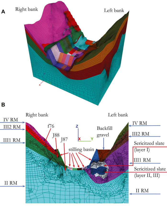
FIGURE 1. (A) Numerical model of the stilling basin of Kala Hydropower Station and the valley at the dam site, (B) A profile across the river (Dam 0 + 145.25 m) showing the lithological strata and geological conditions.
The positive direction of the X-axis of the model is along the river and points downstream. The Y-axis is generally perpendicular to the river channel in the dam site area, with a positive direction from the right bank to the left bank. The positive direction of the Z-axis is vertical upward.
A mesh generation software named Griddle was selected to establish a high-quality grid numerical model. Many practices show that Griddle has strong mesh generation performance in geotechnical simulations. In this study, the eight-node hexahedron element was mainly used in Griddle to mesh the geological model. Four-node tetrahedral elements were used for transition in some parts that are difficult to have meshed with hexahedral elements. Figure 1A shows the numerical model established using Griddle. It has 1156977 solid elements and 577128 nodes. Because of the cross-cutting of strata and faults, the numerical model has 73 element groups. Different colours distinguish these groups.
Figure 1B shows a typical profile crossing through the stilling basin structure. The position coordinate of the profile on the numerical model is X = 160 m, with a realistic chainage 0 + 145.25 m downstream of the dam. For simplification, the chainage of this profile is recorded as “Dam 0 + 145.25 m” in this study. It shows the engineering geological condition and stratigraphic zones in the model. Structural faults J99, F130, J87 and J88 were considered in building the numerical model. According to the engineering survey, the width of these faults was about 0.1–0.25 m. The width of fault f76 was about 0.5 m.
Sericitized slate is a bad geological material encountered in the Kala hydropower project, which would cause potential adverse effects on the construction of stilling basin. Figure 2A shows the spatial relationship between the stilling basin and the sericitized slate. It can be seen that a sericitized slate is located inside the mountain on the left bank. According to the engineering design, a part of sericitized slate will be excavated and exposed as the foundation and slope rock mass, which will contact the bottom plate and sidewall on the left side of the stilling basin. Sericitized slate can be divided into three layers. Among them, the material parameters of the sericitized slate in the second and third layers are similar, so no more detailed stratification is required in this study.
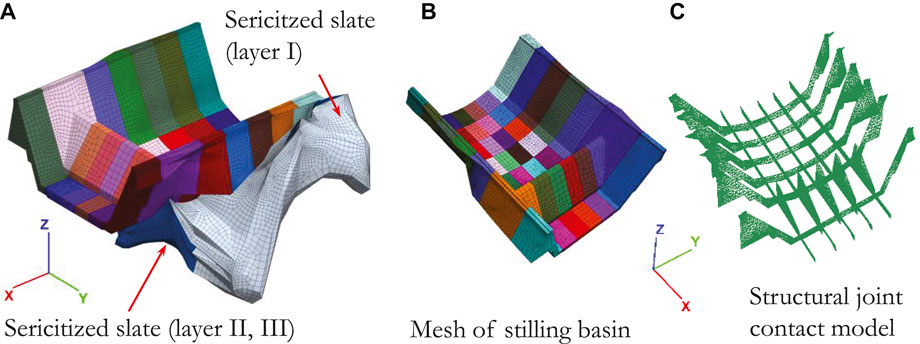
FIGURE 2. (A) Geological model of stilling basin and sericitized slate, (B) Mesh of stilling basin, (C) Structural joint contact model of stilling basin.
Figure 2B shows the three-dimensional numerical model of the hydraulic structure of the stilling basin. The stilling basin structure has 5 structural joints along the river and 6 structural joints across the river. These structural joints are about 2 cm wide and the concrete blocks on both sides are separated from each other. Thus, in the numerical model, interface elements are adopted to simulate the mechanical behaviours of the structural joints, as shown in Figure 2C.
In FLAC3D7.0, the interface element is generally used in contact analysis. The interface element has four mechanical parameters. They are normal stiffness
In this study, the model shown in Figure 1A was imported into FLAC3D7.0 for conducting numerical simulations. FLAC3D7.0 is a finite difference software, which has been developed by Itasca for numerical simulation of geotechnical engineering. In this software, the tensile stress is specified as positive. Therefore, in its calculation results, minor principal stress is equivalent to major principal stress in rock mechanics and engineering. In the numerical model shown in Figure 1A, there are 13 materials involved. Their material parameters are shown in Table 1, which are input into FLAC3D7.0.
Modelling Loads and Boundary Conditions
The following four kinds of loads are taken into account in the numerical analysis.
(1) Deadweight load, which is applied on the model by inputting the values of material density and gravity acceleration (9.81
(2) Hydrodynamic pressure load, which is applied to the surface of the base plate and sidewall of the stilling basin.
(3) Uplift pressure load. It is a type of surface force, which is converted into node force by using the finite element theory and applied to the element nodes at the bottom floor and sidewall of the stilling basin.
(4) Seismic load. It is applied using the pseudo-static method to the effects of an earthquake. According to this method, the model density of some materials is increased by 15%.
The boundary condition of the model is set to constrain the normal displacement at the bottom and the four vertical boundaries of the model.
Working Conditions
During the operation of the hydropower station, the bottom plate of the stilling basin is subjected to various upward and downward loads. Therefore, according to the operation and service conditions of stilling basin, the load combination is divided into forward and reverse load combinations. All forward loads (downward loads) are considered as the maximum value, while reverse loads (upward loads) are not considered or considered as the minimum value. The most adverse combination of upward and downward loads should be considered to ensure the safe operation.
In this study, considering the combination modes of different loads, the engineering mechanical responses of stilling basin structures and bedrocks under 4 working conditions are simulated and analysed, which are presented in Table 2. Concerning the application of load, some special notes should be described as follows:
(1) Under working condition No. 4: normal operation + earthquake, the hydrostatic pressure was applied to the bottom plate and sidewall in a manner of area force. The water level in the stilling basin is EL. 1919.13 m. The water weight is 9.81 kN/m3.
(2) The ground motion acceleration in the direction of earthquake action is 113.6 gal. Under working condition No.4: normal operation + earthquake, the seismic load includes seismic inertia force and seismic hydrodynamic pressure, which are applied using the quasi-static method along the vertical direction. Seismic inertia force is equal to 0.116 times the dead weight. Seismic hydrodynamic pressure is equal to 0.116 times the hydrostatic pressure.
(3) According to the model test results, under working condition No.1: frequent flood, the hydrodynamic pressure = 13 kPa. Under working condition No.2: energy dissipation design flood, fluctuating pressure = 23 kPa. Under working condition No.3: check flood, fluctuating pressure = 18 kPa.
Modelling Results and Analysis
In this study, a series of simulations were carried out. Limited to the length of the paper, only some calculation results are selected for display and analysis below. However, some other valuable simulation results will also be discussed and analyzed in the text descriptions or tables.
Modelling Results of the Whole Model
Figure 3 shows the simulation results under working condition No.1 (frequent flood). It can be seen from Figures 3A,B that under the condition of the frequent flood, the maximum tensile major principal stress is about 32.68kPa. The maximum tensile minor principal stress is about 2.706MPa, which appears on the stilling basin structure.
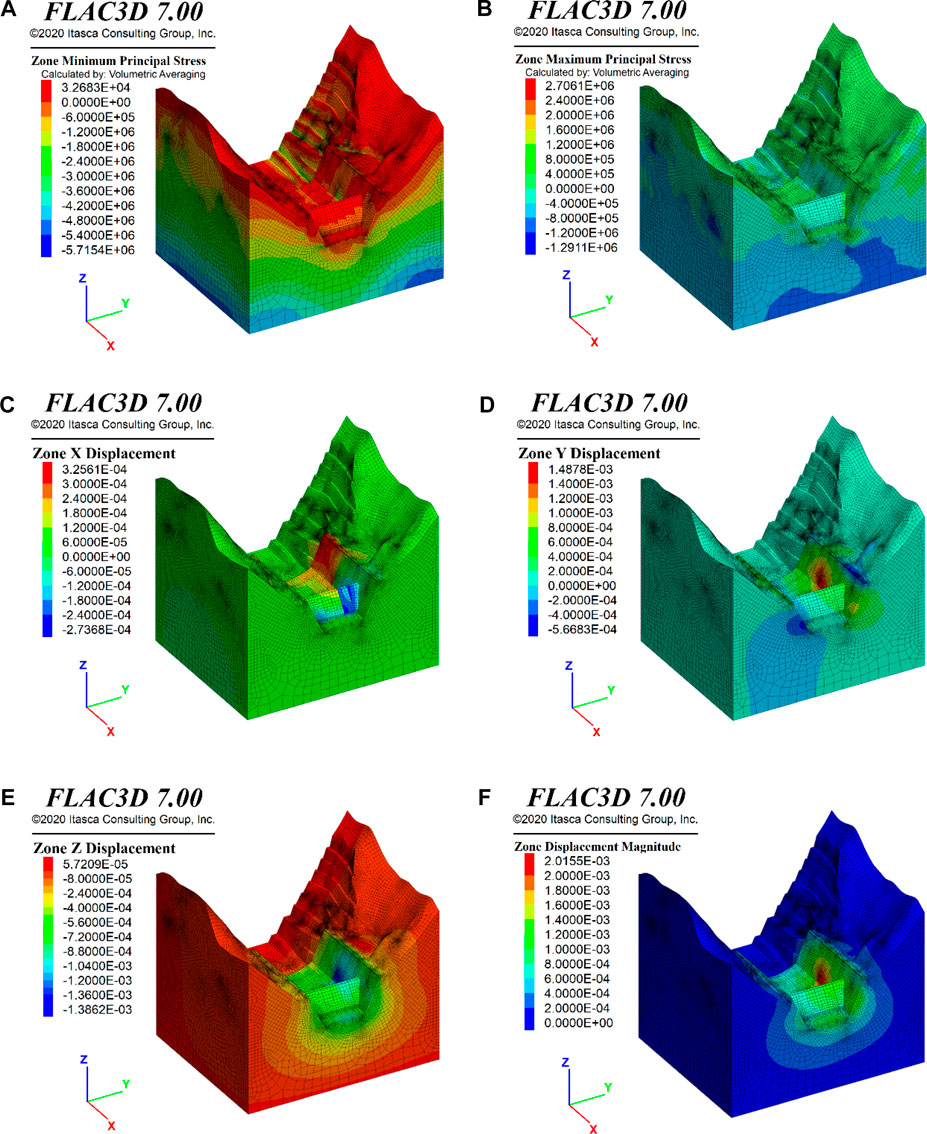
FIGURE 3. Numerical modelling results of the whole model for working condition of the frequent flood: (A) Major principal stress, (B) Minor principal stress, (C) Displacement along the river, (D) Displacement transverse the river, (E) Vertical displacement, (F) Resultant displacement.
Figure 3F shows that under the working condition of the frequent flood, the maximum deformation of the project area is 2.02 mm, which occurs in the middle and lower part of the left sidewall of the stilling basin, with an elevation of about EL. 1895 m. By analysing Figures 3C–E, it can be seen that the deformation in the project area mainly occurs in the transverse and vertical directions. The maximum value of Ydisp is about 1.49 mm and the maximum value of Zdisp is about 1.39 mm, respectively. The value of Xdisp along the river is relatively small.
Modelling Results at the Profile (Dam 0 + 145.25 m)
Figures 4A,B shows the modeling results of major and minor principal stresses on the cross-river profile at Dam 0 + 145.25 m, under working condition No. 2 (energy dissipation design flood). Most areas are in the compressive stress states. There is a tensile stress zone in the shallow layer on the mountain slope, in which the values of tensile major principal stress is in a range of about 0–0.3 MPa. In the backfill gravel at the back of the retaining wall of the stilling basin on the left bank, the local maximum tensile stress value reaches 0.381 MPa. Considering that the backfill gravel is a granular material, this tensile minor principal stress will not cause damage. These tensile stresses can be adjusted and eliminated by the movement between particles.
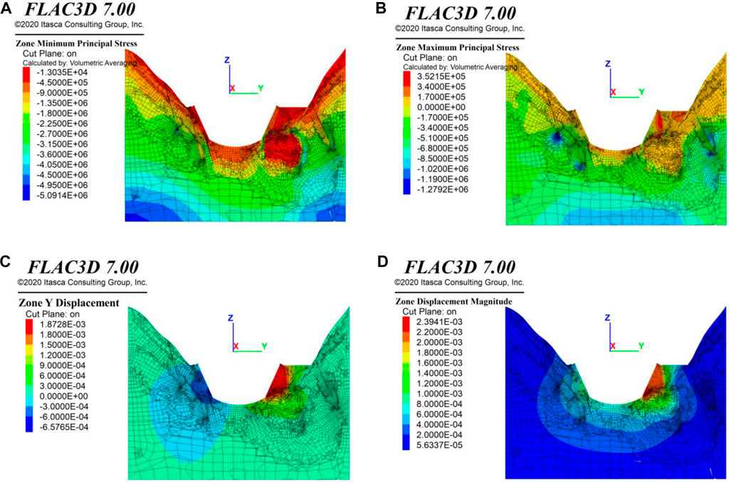
FIGURE 4. Numerical modelling results at the Profile (Dam 0 + 145.25 m) for the working condition of the frequent flood: (A) Major principal stress, (B) Minor principal stress, (C) Displacement transverse the river, (D) Resultant displacement.
Figures 4C,D shows the modelling results of deformation on the cross-river profile at Dam 0 + 145.25 m, under working condition No. 2 (energy dissipation design flood). On this profile, the maximum displacement occurs on the left sidewall (EL. 1895 m) of the stilling basin, with a value of 2.40 mm. The direction of this maximum displacement is from the right bank to the left bank.
Modelling Results at the Profile (Dam 0 + 195.25 m)
Figures 5A,B shows the stress modeling results on the cross-river profile at Dam 0 + 195.25 m, under working conditions of energy dissipation design flood. This profile crosses through the axis of stilling basin dam. It is seen that most areas in this profile are under compressive pressure. In such areas, the interior of the backfill gravel behind the sidewall on the right bank (EL. 1,935 m), the junction between the stilling basin dam and the sidewall on the left bank (EL. 1,914 m), and the junction between the bottom plate on the left bank of the stilling basin dam and sericitized slate (EL. 1,877 m), the minor principal stresses are in the tensile states, within a value range of about 0.15–0.30 MPa.
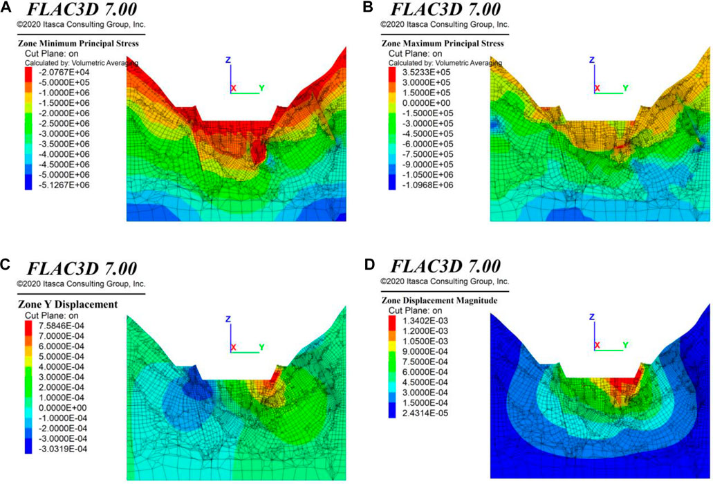
FIGURE 5. Numerical modelling results at the Profile (Dam 0 + 195.25 m) for the working condition of the frequent flood: (A) Major principal stress, (B) Minor principal stress, (C) Displacement transverse the river, (D) Resultant displacement.
Figures 5C,D shows the deformation modeling results at the profile of Dam 0 + 195.25 m, under working conditions of energy dissipation design flood. The maximum displacements occur at the junction of the stilling basin dam crest and the sidewall on the left bank (EL.1901–1,926 m), with a value range of about 1.20–1.34 mm. The direction of maximum displacement is from the right bank towards the left bank. It is found that the deformation of the left bank in this area is larger than that of the same position on the right bank. Through analysis, it is considered that the deformation of the stilling basin dam in this area is mainly affected by the backfill gravel behind the sidewall and the foundation bedrock of the sericitized slate.
Modelling Results of the Stilling Basin
Figure 6 shows the simulation results of deformation of stilling basin, under the working condition of check flood. It is seen that the maximum displacement occurs in a range of EL.1890–1900 m at the left bank sidewall, with a maximum value of about 3.20 mm. The direction of the maximum displacement is towards the left bank slope, which is located in the sericitized slate foundation. Due to the poor engineering properties of the sericitized slate, the lateral deformation of the sidewall on the left bank occurs under the water load in the stilling basin.
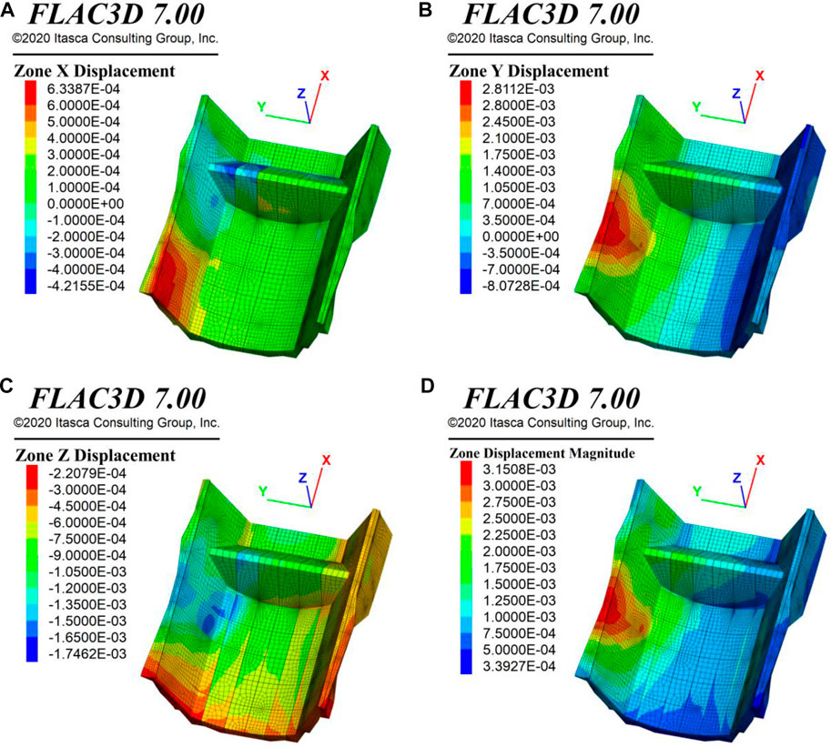
FIGURE 6. Numerical modelling deformation results of stilling basin for working condition of check flood: (A) Xdisp along the river, (B) Ydisp across the river, (C) Vertical displacement, (D) Resultant displacement.
The deformation modelling results of stilling basin structure are summarised in Table 3. It can be seen that the maximum displacements are about 2.02, 2.42 and 3.15 mm, under the working conditions of frequent flood, energy dissipation design flood and check flood, respectively. These maximum displacements occur in the middle and upper part of the sidewall of stilling basin on the left bank. The lateral water pressure in the stilling basin is vertically pressed on the sidewall, resulting in the maximum displacement dominated by the cross-river deformation from the right bank to the left bank.

TABLE 3. Numerical modelling results of displacements of stilling basin under 4 types of working conditions.
Under normal operation + earthquake working condition, the maximum deformation of stilling basin is ahout 3.02 mm. Its direction is mainly across the river from the left bank to the right bank. The maximum deformation occurs at the top of the sidewall of stilling basin (Dam 0 + 85–215 m, EL. 1935 m) on the left bank. It can be seen that earthquake significantly impacts the deformation of stilling basin structure, which can produce opposite deformation different from other working conditions.
Figures 7A,B show the major principal stress distribution in the stilling basin structure under the check flood working condition. It can be seen that most volumes of the stilling basin are in the compressive stress state. At the dam crest and at the top of stilling basin sidewalls on both banks, the major principal stress is in the tensile state, within a value range of 0–0.35 MPa.
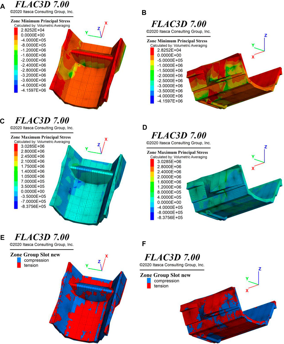
FIGURE 7. Numerical modelling stress results of stilling basin for working condition of check flood: (A,B) Major principal stress, (C,D) Minor principal stress, (E, F) Zones of compression and tension stress.
Figures 7C,D shows the minor principal stress distribution in the stilling basin under check flood working conditions. It can be seen that the minor principal stresses are mainly in the compressive states. Meanwhile, at the top surface and the bottom plate of the stilling basin, the minor principal stresses are in the tensile states, with its value in a range of 0–0.4 MPa.
Figures 7E,F shows that the stilling basin elements are in two stress states of tension and compression under check flood working conditions. It can be seen that more than 2/3 elements of the stilling basin are in the compressive states. And less than 1/3 volume is in the tensile state. The calculation results of other working conditions are similar to those under check flood working conditions.
At the transverse structural joint (Dam 0 + 135–165 m, EL.1,885–1,900 m) in contact with sericitized slate on the back of the stilling basin sidewall on the left bank, there are local concentrations of tensile and compressive stresses. In this region, tensile minor principal stresses and principal compressive stresses can be as high as 3.029 and 4.160 MPa, respectively. Sericitized slate at the transverse structural joint also affects this region’s uneven and uncoordinated deformation.
The concrete structure is easy to be damaged under the condition of tensile stress, so it is necessary to pay special attention to the state of tensile stress. Table 4 summarises the numerical simulation results of major principal tensile stresses in the stilling basin under 4 working conditions. It can be seen that the concrete of stilling basin structure bears a certain degree of tensile stress, but the value of tensile stress is small, within a range of about 0.028–0.057 MPa. This level of tensile stress will not cause harm to the concrete structure. By extracting the values of these tensile stresses, it is found that they are local tensile stresses, which mainly appear in the transverse structural joints of the sidewall on the left bank (Dam 0 + 181 m, EL. 1878 m), with an area of less than 1 m2.

TABLE 4. Numerical modelling results of major principal stress of stilling basin under 4 types of working conditions.
Engineering Evaluation on Sericitized Slate
Three Engineering Evaluation Methods
In this study, the engineering properties of sericitized slate at the foundation of stilling basin was evaluated in three ways:
(1) The standard value of foundation bearing capacity is used for evaluation. When the normal stress applied to the sericitized slate is less than its standard value of foundation bearing capacity, it is considered that the sericitized slate can support the foundation of the stilling basin.
(2) The plastic zone is used for evaluation. When the plastic zone appears in the elements of the sericitized slate, it is considered that the sericitized slate encounters plastic deformation and needs to be strengthened.
(3) The point safety factor is used for the evaluation of strength reserve. When the point safety factor of the sericitized slate is equal to 1.0, it is regarded that the sericitized slate reaches the plastic yield state and does not have enough strength reserve. Reinforcement is needed. When the point safety factor is greater than 1.0, the sericitized slate is in an elastic state. The larger the point safety factor, the higher the strength reserve. The point safety factor method and related theories will be introduced below.
Point Safety Factor Method and Related Theories
In geotechnical engineering, using the idea of limit equilibrium, the point safety factor of geomaterials can be defined. Based on the Mohr-Coulomb strength criterion, the distance between the stress state of a point and the strength envelope can be determined, as shown in Figure 8. The calculation formula of the point safety factor under compressive stress state can be defined as follows:
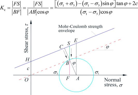
FIGURE 8. Definition of stress state at a point, Mohr-Coulomb strength line and point safety factor.
However, the stresses in geomaterials are not always in the compressive state. When the stress state of a point is in tension, the tensile strength criterion should be adopted. In this case, the point safety factor is defined as follows:
Engineering Evaluation and Analysis
(1) Evaluating foundation bearing capacity
Take the characteristic value (400 kPa) of the foundation bearing capacity of sericitized slate (Layer 2 and 3) as the standard. After excavation, the exposed area of the sericitized slate, contacting to the foundation of stilling basin, is shown in Figure 9. It can be seen that, under normal operation + earthquake working condition, in most areas, the vertical normal stress Szz on the top surface of sericitized slate is less than 400 kPa. Only in the small areas along the edges, the vertical normal stress Szz is greater than 400 kPa. Therefore, it can be regarded that the foundation bearing capacity of sericitized slate meets the engineering requirements. Similar research conclusions can also be obtained by analyzing the calculation results of other working conditions.
(2) Evaluating plastic zones
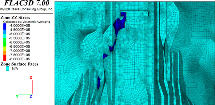
FIGURE 9. The vertical normal stress Szz higher than 400 kPa of sericitized slate at the bottom of stilling basin.
The calculation results show that, under 3 working conditions of the frequent flood, energy dissipation design flood and check flood, the sericitized slate is in the elastic state and has no plastic zone. Under the working condition of normal operation + earthquake, as shown in Figure 10, most sericitized slate is in the elastic state. However, there is a large plastic zone observed in the location (Dam 0 + 83–101 m, EL. 1928.3–1932.8 m). The volume of the plastic zone is about 18 m long, 4.5 m wide and 3.3–5.0 m deep.
(3) Evaluating point safety factor
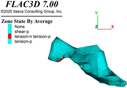
FIGURE 10. Plastic zones in the sericitized slate under working condition of normal operation + earthquake.
Figure 11 shows the calculated values of the point safety factor in the sericitized slate under 4 working conditions. It is found that the point safety factor in the sericitized slate changes with working conditions. In general, the point safety factors in the most areas of the sericitized slate are greater than 3.5, indicating that these areas have high strength reserves and are not easy to be damaged. Only in the local area near the sidewall of the stilling basin (roughly the same as the plastic zone), the value of the point safety factor is close to 1.0, indicating that the strength reserve in these areas is insufficient.
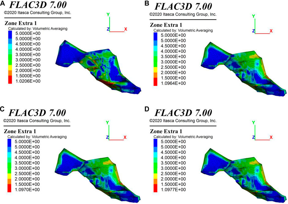
FIGURE 11. Point safety factor of sericitized slate for the working condition of (A) Frequent flood, (B) Energy dissipation design flood, (C) Check flood, (D) Normal operation + earthquake.
Conclusions and Engineering Suggestions
In this study, a three-dimensional finite-difference numerical model was built based on the layout of the stilling basin and the geological conditions of the Kala hydropower station. By carrying out a series of numerical simulations under 4 working conditions, the following conclusions can be summarised:
1. Under 4 working conditions, the bank slopes and stilling basin are mainly in the compressive stress states. The tensile minor principal stresses are in a range of 2.317–3.321 MPa. However, the range of tensile major principal stresses is 0.118–0.133 MPa. In addition, it can be seen that there is a certain degree of tensile stresses in the shallow layers of the slopes on both banks, which are about 0–0.4 MPa.
2. Under the working conditions of the frequent flood, energy dissipation design flood and check flood, the positions of maximum displacements gradually rise from EL.1888–1902 m at the lower part of the sidewall of the stilling basin to EL.1917–1935 m at the top of the sidewall on the left bank. The maximum displacements are from the right bank towards the left bank. Under the normal operation + earthquake working condition, the maximum displacement of stilling basin is 3.02 mm, with its direction towards the right bank.
3. Under 4 working conditions, the major principal stresses in the most areas of stilling basin are mainly under compressive states. However, in some parts of the stilling basin, there are major principal stresses in the tensile state, mainly in the transverse structural joints on the left sidewall of the stilling basin (Dam 0 + 181 m, EL. 1878 m). Because the values of tensile stresses are small in a range of 0.028–0.133 MPa, they would not harm the concrete structure of the stilling basin.
4. Under 4 working conditions, the values of vertical normal stresses Szz pressed on the sericitized slate beneath the stilling basin foundation is less than 400 kPa (foundation bearing capacity of the sericitized slate). This indicates that sericitized slate can meet the foundation bearing requirements of the stilling basin in these areas.
5. Under 3 working conditions: frequent flood, energy dissipation design flood and check flood, the sericitized slate is in the elastic state and has no plastic zone. Under normal operation + earthquake working conditions, a large tensile plastic zone appears in the sericitized slate located in Dam 0 + 83–101 m and EL 1928.3–1932.8 m. The volume of the plastic zone is 18 m long, 4.5 m wide and 3.3–5.0 m deep.
6. Under 4 working conditions, the point safety factors in most areas of sericitized slate are greater than 3.0. This indicates that the sericitized slate has high strength reserve. However, the point safety factors that are close to 1.0 appear in the areas coinciding with plastic zones. This indicates that the strength reserve in these areas is slightly insufficient.
7. Based on the above analysis, it can be determined that the sericitized slate can be used as the foundation bearing layer of the stilling basin. However, the sericitized slate might be weakened in water. In practical engineering, it is strongly recommended to conduct necessary foundation treatment to strengthen the engineering properties of sericitized slate.
Data Availability Statement
The original contributions presented in the study are included in the article/Supplementary Material, further inquiries can be directed to the corresponding author.
Author Contributions
Conception and design of this study were mainly contributed by KQ and JX. Numerical simulations were mainly contributed by JX and ZC. Drafting the manuscript was mainly contributed by JX and XS.
Funding
This research was financially supported by the Fundamental Research Funds for the Central Universities (B19020049, B200201059) and National Natural Science Foundation of China, grant numbers (12062026, 51808191, 51709089).
Conflict of Interest
Author JX was employed by PowerChina Huadong Engineering Corporation Limited.
The remaining authors declare that the research was conducted in the absence of any commercial or financial relationships that could be construed as a potential conflict of interest.
Publisher’s Note
All claims expressed in this article are solely those of the authors and do not necessarily represent those of their affiliated organizations, or those of the publisher, the editors and the reviewers. Any product that may be evaluated in this article, or claim that may be made by its manufacturer, is not guaranteed or endorsed by the publisher.
References
1. Chang X, Liu X, Zhou W. Hydropower in China at Present and its Further Development. Energy (2010) 35:4400–6. doi:10.1016/j.energy.2009.06.051
2. Tang X, Zhou J. A Future Role for cascade Hydropower in the Electricity System of China. Energy Policy (2012) 51:358–63. doi:10.1016/j.enpol.2012.08.025
3. Wang SJ, Li GH, Zhang Q, LLC . Engineering Geological Study of the Active Tectonic Region for Hydropower Development on the Jinsha River, Upstream of the Yangtze River. Acta Geologica Sinica - English Edition (2000) 74:353–61.
4. Qi S, Wu F, Yan F, Lan H. Mechanism of Deep Cracks in the Left Bank Slope of Jinping First Stage Hydropower Station. Eng Geology (2004) 73:129–44. doi:10.1016/j.enggeo.2003.12.005
5. Dai F, Li B, Xu N, Meng G, Wu J, Fan Y. Microseismic Monitoring of the Left Bank Slope at the Baihetan Hydropower Station, China. Rock Mech Rock Eng (2017) 50:225–32. doi:10.1007/s00603-016-1050-9
6. Feng X-T, Hao X-J, Jiang Q, Li S-j., Hudson JA. Rock Cracking Indices for Improved Tunnel Support Design: A Case Study for Columnar Jointed Rock Masses. Rock Mech Rock Eng (2016) 49:2115–30. doi:10.1007/s00603-015-0903-y
7. Jiang Q, Feng X-t., Hatzor YH, Hao X-j., Li Sj. Mechanical Anisotropy of Columnar Jointed Basalts: An Example from the Baihetan Hydropower Station, China. Eng Geology (2014) 175:35–45. doi:10.1016/j.enggeo.2014.03.019
8. Zhang JC, Xu WY, Wang HL, Wang RB, Meng QX, Du SW. A Coupled Elastoplastic Damage Model for Brittle Rocks and its Application in Modelling Underground Excavation. Int J Rock Mech Mining Sci (2016) 84:130–41. doi:10.1016/j.ijrmms.2015.11.011
9. Cai M, Kaiser PK. Assessment of Excavation Damaged Zone Using a Micromechanics Model. Tunnelling Underground Space Technology (2005) 20:301–10. doi:10.1016/j.tust.2004.12.002
10. Hao X-J, Feng X-T, Yang C-X, Jiang Q, Li SJ. Analysis of EDZ Development of Columnar Jointed Rock Mass in the Baihetan Diversion Tunnel. Rock Mech Rock Eng (2016) 49:1289–312. doi:10.1007/s00603-015-0829-4
11. Li S, Feng X-T, Li Z, Zhang C, Chen B. Evolution of Fractures in the Excavation Damaged Zone of a Deeply Buried Tunnel during TBM Construction. Int J Rock Mech Mining Sci (2012) 55:125–38. doi:10.1016/j.ijrmms.2012.07.004
12. Chen WZ, Zhu WS, Shao JF. Damage Coupled Time-dependent Model of a Jointed Rock Mass and Application to Large Underground Cavern Excavation. Int J Rock Mech Mining Sci (2004) 41:669–77. doi:10.1016/j.ijrmms.2003.01.003
13. Alemdag S, Gurocak Z, Solanki P, Zaman M. Estimation of Bearing Capacity of Basalts at the Atasu Dam Site, Turkey. Turkey: Bulletin of Engineering Geology and the Environment (2008).
Keywords: kara hydropower station, stilling basin structure, sericitized slate, engineering evaluation, foundation bearing capacity
Citation: Xu J, Cui Z, Qian K, Sun X and Xu J (2022) Three-Dimensional Numerical Analysis and Engineering Evaluation of Stilling Basin and Foundation Bedrock of Kala Hydropower Station, China. Front. Phys. 9:807506. doi: 10.3389/fphy.2021.807506
Received: 02 November 2021; Accepted: 30 November 2021;
Published: 21 January 2022.
Edited by:
Wanqing Shen, Université de Lille, FranceReviewed by:
Susheng Wang, China University of Mining and Technology, ChinaXiaohu Zhang, Guizhou University of Engineering Science, China
Copyright © 2022 Xu, Cui, Qian, Sun and Xu. This is an open-access article distributed under the terms of the Creative Commons Attribution License (CC BY). The use, distribution or reproduction in other forums is permitted, provided the original author(s) and the copyright owner(s) are credited and that the original publication in this journal is cited, in accordance with accepted academic practice. No use, distribution or reproduction is permitted which does not comply with these terms.
*Correspondence: Kun Qian, MTQ1ODI4ODAyMUBxcS5jb20=
 Jianjun Xu1
 Kun Qian
 Xiang Sun
 Jie Xu
