 Bo Ma
Bo Ma Feng Wang
 Hongyang Liu1
- 1College of Energy and Mining Engineering, Shandong University of Science and Technology, Qingdao, China
- 2State Key Laboratory of Mining Disaster Prevention and Control Co-Founded By Shandong Province and the Ministry of Science and Technology, Shandong University of Science and Technology, Qingdao, China
- 3School of Mining Engineering, University of Science and Technology Liaoning, Anshan, China
A comprehensive understanding of the mechanical properties of coal and rock sections is necessary for interpreting the deformation and failure modes of such underground sections and for evaluating the potential dynamic hazards. However, most studies have focused on horizontal coal–rock composites and the mechanical properties of inclined coal–rock composites have not been considered. To explore the influence of different confining pressures and inclined coal seam thicknesses on the mechanical properties and failure characteristics of rock–coal–rock (RCR) composites, a numerical model based on the particle flow code was used to perform simulations on five inclined RCR composites at different confining pressures. The results show that the mechanical properties and failure characteristics of the RCR composites are affected considerably by the inclined coal seam thickness and the confining pressure. (1) When the inclined coal seam thickness is constant, the elasticity modulus of the inclined RCR composite increases nonlinearly with the confining pressure at first, and then remains constant. At the same confining pressure, the elasticity modulus of the inclined RCR composite decreases nonlinearly with the inclined coal seam thickness. (2) When the confining pressure is constant, the peak stress of the inclined RCR composite decreases with the increase of the inclined coal seam thickness. When the inclined coal seam thickness is constant, the peak stress increases with the confining pressure. (3) As the inclined coal seam thickness increases, the peak strain of the inclined RCR composite first decreases rapidly, and then remains constant when there is no confining pressure. When the confining pressure is between 5 and 20 MPa, the peak strain of the inclined RCR composite gradually increases. (4) In the absence of confining pressure, there are few microcracks in the rock at an inclined coal seam thickness of 10 mm, whereas all the other cracks are in the coal section. When the confining pressure ranges between 5 and 20 MPa, the failure modes of the RCR composite can be divided into Y- and X-types.
Introduction
With the continuous and growing demand for energy, excavation of the nearly fully exploited shallow coal seams has shifted to mining deep coal resources. In shallow environments, the failure of coal and rock mass is mainly controlled by its own fractured structural plane. However, under larger depth conditions, the failure of coal and rock mass is not only affected by its own fractured structural plane but also by the overall structure of the coal–rock combination. In addition, many disasters in mines exhibit the phenomenon of overall failure and instability of coal and rock. The roof, coal seam, and floor form a dynamic mechanical equilibrium system. Disturbance due to mining activities will cause damage to the coal; at the same time, it will cause damage to the adjacent roof and floor rock sections, which in turn cause the overall instability and damage of the coal–rock composite system, thus leading to coal–rock dynamic disasters, such as roof fall, rock burst, coal and gas outburst, and floor water inrush [1–5]. Therefore, the interaction between surrounding rock and coal is one of the key factors responsible for the maintenance of the overall dynamic balance of the coal–rock composite system [6, 7]. In addition, different external forces affect the macro-mechanical properties of the coal–rock composite owing to its complex internal structure. A comprehensive understanding of the mechanical properties of coal and rock sections is necessary for interpreting the deformation and failure modes of underground coal and rock sections and for evaluating the potential dynamic hazards.
At present, generally, laboratory experiments and numerical simulation are mainly used to study the mechanical properties and failure behavior of coal–rock composites, analyze the influence of various factors, and obtain meaningful results. Petukhov et al. proposed the stability problem of the coal–rock composite system (composed of roof, floor, and coal seams) in their study on the post-peak deformation and stability of rock materials [8]. conducted uniaxial and triaxial compression tests with four different inclination angles and obtained the relationship between inclination angle, confining pressure, failure strength, and cohesion of the coal–rock composite [9]. Huang et al. conducted uniaxial compression tests on a coal–rock composite at different loading rates, and found the elasticity modulus, peak strength, and residual strength of the coal–rock composite of the roof, coal, and floor [10]. To study the influence of rock strength on the instability of the coal–rock section, Liu et al. conducted uniaxial compression tests on rock–coal–rock (RCR) composite samples at different rock strengths and analyzed the influence of rock strength on the mechanical behavior and fracture mode of the samples [11]. Several previous studies carried out uniaxial compression tests on coal–rock combinations with different rock–coal height ratios to study the influence of rock–coal height ratio on the mechanical properties and progressive failure mechanism of coal–rock combinations. These studies found that the macroscopic failure initiation stress, peak stress, uniaxial compressive strength, and elastic modulus of coal–rock combinations appear as the rock–coal height ratio decreases [12–15]. Wu et al. conducted an experimental analysis and theoretical verification of rock–coal–anchor (RCB) composite material systems from different angles, and found that the failure of rock–coal composite specimens was caused by tensile and shear cracks, and the reinforcement formed in the composite material system after anchoring limited the areas where cracks might appear in the specimens [16]. Other studies conducted uniaxial and triaxial compression tests on coal–rock composite samples combined in different manners to study their mechanical properties and failure characteristics [17–19]. Li et al. used the FLAC numerical simulation software to conduct impact tendency experiments with coal–seam–floor composite samples at three different height ratios (1∶1, 1∶2, and 2∶1) and three different inclination angles (0°, 30°, and 45°) [20]. Zhao et al. used the RFPA numerical simulation software to study the influence of different coal-to-rock height ratios and different roof strengths, thicknesses, homogeneity, and contact angles on the impact tendency of coal–rock composite samples [21]. Guo et al. used the particle flow code two-dimensional software (PFC2D) to simulate uniaxial and biaxial compression tests of coal–rock composite samples at different coal-to-rock strength ratios and height ratios. The influence of rock-to-coal strength ratio and height ratio on the impact trend, failure mode, and ultimate compressive strength characteristics of the composite sample have been analyzed thoroughly from a mesoscopic perspective [22]. Zhao et al. analyzed the failure characteristics of CR (Coal Rock association) assemblies with various inclination angles (0°, 15°, 30°, and 45°), analyzed their failure mechanisms [23]. Wu et al. conducted experiments on RCB specimens with different angles under different stress states, and found that the fracture tendency of RCB specimens increased with the increase of angle [24].
However, most studies have focused on horizontal coal–rock combinations, while the mechanical properties of inclined coal–rock combinations are relatively less considered. The research scope has been mostly on the coal–rock composite model itself and its overall mechanical properties, whereas studies that have considered the influence of different confining pressures and different inclined coal seam thicknesses on the failure characteristics and mechanical properties of the composite are few. China has a large reserve of inclined thin coal seams; coal seams at an inclination angle greater than 30° account for more than 20% of China’s total coal reserves [24]. Therefore, the PFC2D numerical simulation software was used in this study to analyze the mechanical properties and failure characteristics of an RCR composite formed by mudstone and coal that are common in the roof of an underground mine with simulated uniaxial and biaxial compression tests. The influence of different confining pressures and inclined coal seam thicknesses on the mechanical properties and failure characteristics of the RCR composite are studied to obtain the deformation and instability mechanism of the RCR composite.
Numerical Method and Parameter Selection
Numerical Method
PFC is a numerical simulation software for discontinuous media that combines meso-mechanics with the numerical calculation method on the basis of the particulate discrete element modeling approach. The macroscopic mechanical behavior of the model is realized by changing the meso-mechanical parameters of the particles. Here, PFC includes the contact bonding model (CBM), parallel bonding model (PBM), smooth-joint contact model (SJM), and flat-joint model (FJM), etc. PBM can transmit force and moment and defines the macro stiffness using both the contact and bonding stiffnesses, which is more suitable for simulating the characteristics of rock-like materials. Therefore, this study chooses PBM for the numerical simulation.
Numerical Modeling
To study the influence of inclined coal seam thickness on the mechanical properties and failure characteristics of the RCR composite, five RCR composite samples with different inclined coal seam thicknesses were designed. The model has a height of 100 mm and a width of 50 mm, and the coal section is inclined at 30°. The sample has top and bottom layers made of rock, whereas the middle layer is made of coal. The inclined coal section (the black middle section of the sample) has thicknesses of 10, 20, 30, 40, and 50 mm. The confining pressure is set at 0, 5, 10, 15, and 20 MPa, as shown in Figure 1; Figure 2. The detailed dimensions of the inclined RCR composite samples at different confining pressures are summarized in Table 1. Besides, studied the influence of the loading rate on the mechanical behavior of intact granite by PFC2D and revealed that when the loading rate changes from 0.001 to 0.05 m/ s, the mechanical behavior changes slightly [25]. Therefore, based on the literature review, the loading velocity of 0.01 m/ s was chosen in this numerical simulation, and loading was applied until failure.
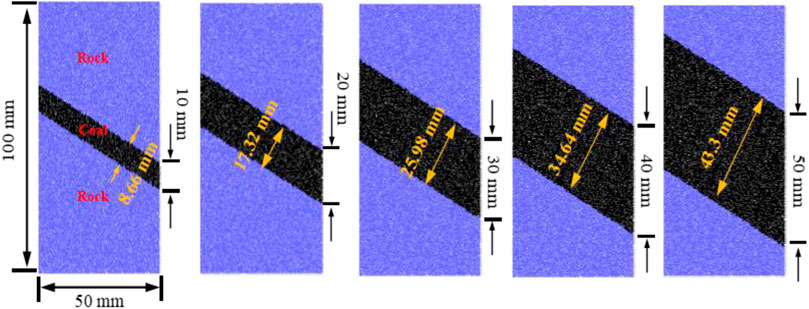
FIGURE 1. Samples with different inclined coal seam thickness.
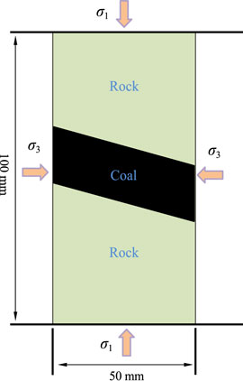
FIGURE 2. Schematic diagram of numerical model loading of the RCR composite samples.
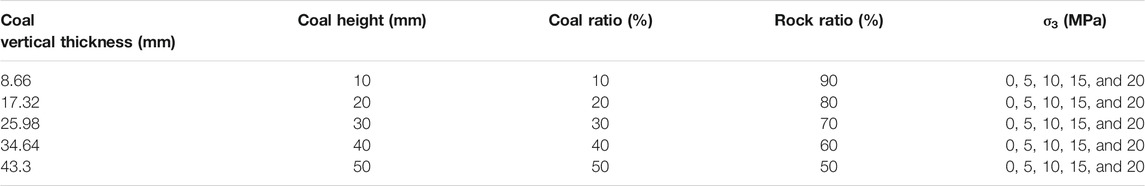
TABLE 1. The detailed dimensions of the inclined RCR composite samples at different confining pressures.
Microscopic Parameter Determination
Before performing the numerical simulation, it was necessary to verify the micro-parameters so that the numerical parameters are consistent with those obtained in the laboratory [26–29]. In this study, the parameter calibration method was used to calibrate the coal and rock parameters. The determination of microscopic parameters in PFC2D is shown in Figure 3. As there is no direct quantitative relationship between the meso-mechanical parameters of PFC numerical simulations and the macro-mechanical parameters of laboratory tests, it is difficult to determine meso-mechanical parameters based on laboratory tests. To obtain reasonable meso-mechanical parameters, uniaxial compression tests of the complete samples were conducted, the meso-mechanical parameters of the numerical simulation model were calibrated repeatedly until the results of the numerical.

Simulation test were similar to the laboratory test results obtained before the PFC numerical simulation test was conducted. The microscopic parameters used in the numerical coal and rock model are listed in Table 2 [32].
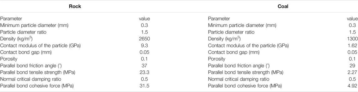
TABLE 2. Microscopic parameters of rock and coal.
The comparison between the experimental and numerical simulation results of the mechanical parameters of coal and rock are listed in Table 3. The uniaxial compression stress–strain curve of coal and rock is shown in Figure 4. It can be observed from Table 3 that, in terms of peak strength and elasticity modulus, the experimental results of the mechanical parameters of the coal and rock samples are not considerably different from the numerical simulation results, as the errors are within 1.85%. This is consistent with the trends of the two sets of curves in Figure 4, which indicate that the elasticity modulus and peak strength obtained by numerical simulation are consistent with the results of the laboratory uniaxial compression test. In terms of peak strain, the experimental and numerical simulation results of mechanical parameters of both the coal and rock samples are relatively large, with errors exceeding 10%. Compared with the rock samples, the coal samples yield larger errors that exceed 25%. The reason for these errors can be inferred from Figure 4. The stress–strain curve obtained by the numerical simulation in Figure 4 is almost a straight line before the peak stress is reached. Compared with the stress–strain curve of the laboratory uniaxial compression test, the compaction stage is not present. This is because PFC simulates the motion and mechanical properties of rock sections using the generated round rigid particles, which do not deform after they are subjected to force, such that the compaction of primary voids does not occur, thus making it impossible to reflect the initial compaction stage of the samples, which occurs in laboratory tests. Therefore, the peak strain obtained by the numerical simulation is smaller than that obtained by the laboratory uniaxial compression test for both the coal and rock samples. Moreover, the coal samples have lower strengths, homogeneity, and higher porosity than the rock samples; their compaction times during the laboratory uniaxial compression test are longer. Therefore, the errors between the experimental and the numerical simulation results for the mechanical parameters of the coal samples are larger than those of the rock samples.
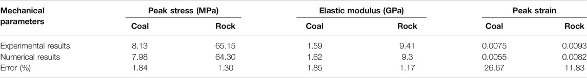
TABLE 3. The comparison between the experimental and numerical simulation results of the mechanical parameters of coal and rock.
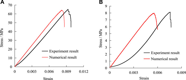
FIGURE 4. Uniaxial compression stress–strain curve of coal and rock. (A) Rock specimen; (B) Coal specimen.
Numerical Simulation Result Analysis
Deviatoric Stress–Strain Curve
The axial deviatoric stress–strain curves of the RCR composites at different inclined coal seam thicknesses and different confining pressures are shown in Figure 5; the overall trends of the several groups of curves are the same. Around the peak value, the deviatoric stress–strain curve shows a relatively significant stress drop, exhibiting a step-like upward fluctuation. This is because the loading rate of this numerical simulation test is very low. At a low-loading rate, there is sufficient time for the microcracks in the sample to evolve and develop to cause macroscopic failure; the corresponding stress curve shows a stress drop. At the same time, the sample has time to adjust the internal structure to adapt to the axial stress, such that after the stress drop, the stress increases again and reaches the peak value. After reaching the peak value, the deviatoric stress–strain curve did not drop rapidly, but rather exhibited a steep cliff. This is attributed to the fact that after the sample reaches the peak stress, the loading is not stopped, but continues at a low rate, thus allowing the sample to have sufficient time to recombine and attain a specific resistance.
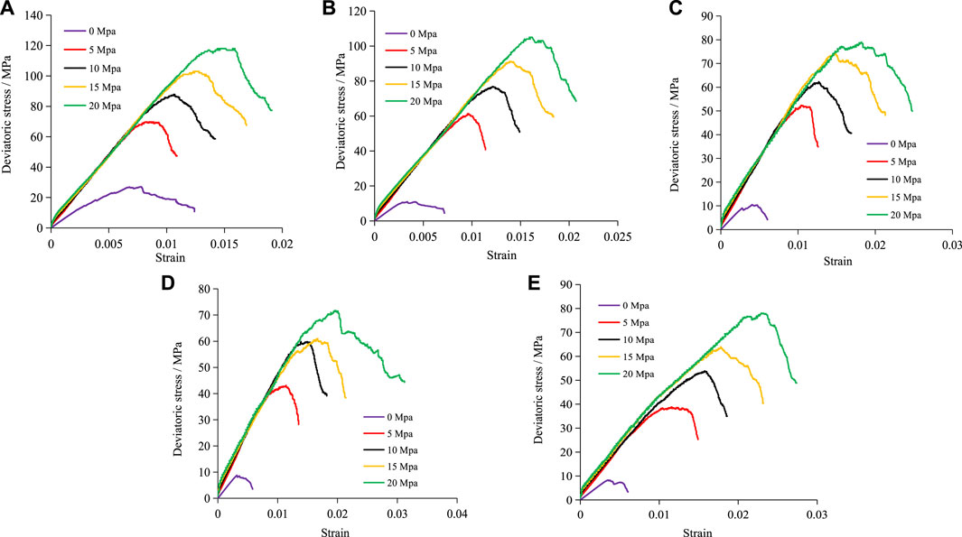
FIGURE 5. The axial deviatoric stress–strain curves of the RCR composites at different inclined coal seam thicknesses and different confining pressures. (A) Coal thickness 10 mm; (B) Coal thickness 20 mm. (C) Coal thickness 30 mm; (D) Coal thickness 40 mm (E) Coal thickness 50 mm.
With the same inclined coal seam thickness, the yield and peak stresses of the RCR composite gradually increase as the confining pressure increases. With the same confining pressure, the yield and peak stresses of the RCR composite gradually decrease as the inclined coal seam thickness increases. Compared with composites of other inclined coal seam thicknesses, the composite with a thickness of 10 mm at a confining pressure of 0 MPa has a larger peak strain, and yield and peak stresses. This indicates that in the absence of the confining pressure, the thinner the inclined coal is, the stronger is its bearing capacity, the longer it takes for the cracks to penetrate the coal, and the longer the overall time is for sample failure.
Mechanical Properties of RCR Composite Samples at Different Inclined Coal Seam Thicknesses and Confining Pressures
Tables 4, 5, 6 summarize the peak stress, peak strain, and elasticity modulus, respectively, of the RCR composites at different inclined coal seam thicknesses and at different confining pressures. Based on these results, it can be observed that the deformation characteristics and strength of the RCR composites are not only related to the inclined coal seam thickness, but also to the confining pressure.
It can be observed from Table 4 that under the same confining pressure, as the inclined coal seam thickness increases, the peak stress of the composite sample gradually decreases. This reduction reaches a maximum and minimum value of 69.26 and 29.42% when the confining pressures are 0 and 20 MPa, respectively, thus indicating that the larger the confining pressure is, the smaller the reduction in the peak stress of the composite samples is as a function of the inclined coal seam thickness. At the same inclined coal seam thickness, as the confining pressure increases, the peak stress of the composite sample gradually increases. This increase reaches a maximum of 11.78 times when the inclined coal seam thickness is 50 mm, and a minimum of 4.13 times when the inclined coal seam thickness is 10 mm, thus indicating that the larger the inclined coal seam thickness is, the greater the increase in the peak stress of the composite samples is as a function of the confining pressure.
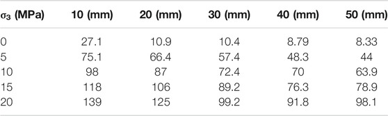
TABLE 4. Peak Stress (MPa) of the RCR composites at different inclined coal seam thicknesses and different confining pressures.
It can be observed from Table 5 that with the increase of the inclined coal seam thickness, when the confining pressure is 0 MPa, the peak strain of the composite sample gradually decreases; by contrast, when the confining pressure is 5–20 MPa, the peak strain of the composite sample gradually increases. This increase reaches a maximum of 56.76% when the confining pressure is 20 MPa and a minimum of 33.33% when the confining pressure is 5 MPa, thus indicating that the larger the confining pressure is, the larger the increase in the peak strain of the composite samples is as the inclined coal seam thickness increases. At the same inclined coal seam thickness, as the confining pressure increases, the peak strain of the composite samples gradually increases. This increase reaches a maximum of 5.63 times when the inclined coal seam thickness is 50 mm, and a minimum of 0.9 times when the inclined coal seam thickness is 10 mm, thus indicating that the larger the inclined coal seam thickness is, the greater the increase in the peak strain of the composite samples is as the confining pressure increases.
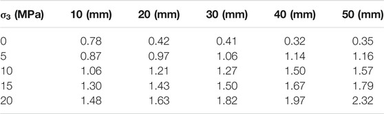
TABLE 5. Peak Strain (10–2) of the RCR composites at different inclined coal seam thicknesses and different confining pressures.
It can be observed from Table 6 that at the same confining pressure, as the inclined coal seam thickness increases, the elasticity modulus of the composite sample gradually decreases. This reduction reaches a maximum of 67.41% when the confining pressure is 15 MPa and a minimum of 35.57% when the confining pressure is 0 MPa, thus indicating that the larger the confining pressure is, the greater the reduction in the elasticity modulus of the composite samples is as a function of the inclined coal seam thickness. With the same inclined coal seam thickness, as the confining pressure increases, the elasticity modulus of the composite samples gradually increases. This increase reaches a maximum of 1.32 times when the inclined coal seam thickness is 10 mm and a minimum of 22.22% when the inclined coal seam thickness is 50 mm, thus indicating that the smaller the inclined coal seam thickness is, the greater is the increase in the elasticity modulus of the composite samples as the confining pressure increases.
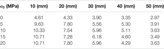
TABLE 6. Elastic Modulus (GPa) of the RCR composites at different inclined coal seam thicknesses and different confining pressures.
Influence of Confining Pressure and Inclined Coal Seam Thickness on the Peak Stress of RCR Composite Samples
As shown in Figure 6A, the peak stress of the RCR composite samples shows an overall increasing trend as the confining pressure increases. When the confining pressure increases from 0 to 5 MPa, the peak stress increases continuously. Thus, the smaller the inclined coal seam thickness is, the higher the rate of increase of peak stress is. Compared with rock sections, coal has lower strength and homogeneity, and applying the confining pressure strengthens the coal section. The increase of strength of the coal section increases the overall strength of the composite sample, and the smaller the thickness of the inclined coal seam is, the stronger the confining pressure on the coal is, and the greater the overall strength of the composite sample is. When the confining pressure increases from 5 to 10 MPa, the peak stress increases at a slower rate, thus, indicating that as the confining pressure continues to increase, the rate of increase in the strength of the composite sample gradually decreases. When the confining pressure increases to 15 and 20 MPa, the strength of the composite sample still increases as the confining pressure increases, but there is no major difference in the rate of increase of strength owing to the confining pressure.
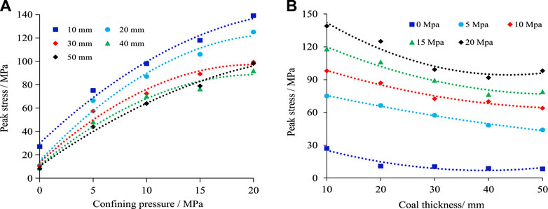
FIGURE 6. Peak Stress of the RCR composites at different inclined coal seam thicknesses and different confining pressures. (A) Influence of different confining pressure; (B) Influence of different coal thickness.
The influence of the confining pressure on the strength of the composite sample can be explained based on two situations. When the confining pressure is low, it has a significant influence on the strength of the composite sample; however, when the confining pressure is high, the strength of the composite sample becomes insensitive to the influence of the confining pressure. This is attributed to the fact that compared with uniaxial compression alone, the confining pressure applied ensures that the external force acts on the originally loose coal section such that the coal section undergoes a compaction process, wherein its strength is increased considerably. As the confining pressure continues to increase, the strength of the already dense coal section that has been compressed by the confining pressure begins to increase slowly in a manner similar to the elastic deformation stage subject to uniaxial compression. At this time, the strength of the sample exhibits a linear growth, and the role of the confining pressure is no longer to strengthen the coal section, but to limit the crack propagation and increase the strength of the composite sample.
As shown in Figure 6B, the peak stress of the RCR composite samples shows an overall decreasing trend as the inclined coal seam thickness increases. This shows that under the same geological engineering conditions, the bearing capacity of the coal seam increases as the coal seam thickness decreases. At different confining pressures, the influence of the inclined coal seam thickness on the peak stress of the composite samples is different.
When the confining pressure is 0 MPa, the peak stress of the composite samples decreases from 27.1 to 10.9 MPa as the inclined coal seam thickness increases from 10 to 20 mm; whereas the peak stress of the composite samples remains almost constant as the inclined coal seam thickness increases coal seam thickness increases from 20 to 50 mm. When the confining pressure is 5 or 10 MPa, as the inclined coal seam thickness increases, the peak stress of the composite samples decreases in a nonlinear manner. When the confining pressure is 15 or 20 MPa, the peak stress of the composite samples decreases nonlinearly as the inclined coal seam thickness increases from 10 to 40 mm; whereas the peak stress of the composite samples increases again as the thickness of the inclined coal increases from 40 to 50 mm.
The influence of the inclined coal seam thickness on the strength of the composite samples can be explained based on two situations. As the inclined coal seam thickness increases at a confining pressure of 0 MPa, the strengths of the composite samples decrease rapidly. At different coal seam thicknesses, the strengths of the composite samples is approximately the same; when the confining pressure of the composite samples ranges between 5 and 20 MPa, the strength of the composite samples decreases at a slower rate, and the rate of decrease in the strength of the composite samples at different coal seam thicknesses is approximately the same.
Influence of Confining Pressure and Inclined Coal Seam Thickness on the Peak Strain of RCR Composite Samples
As shown in Figure 7A, at the same coal thickness, the peak strain of the composite samples exhibits an overall increasing trend as the confining pressure increases. When the confining pressure is less than 5 MPa, the peak strain of the composite samples increases slowly at the inclined coal seam thickness of 10 mm as a function of the confining pressure; by contrast, the peak strain increases rapidly at other inclined coal seam thicknesses as a function of the confining pressure. When the confining pressure is greater than 5 MPa, the peak strain of the composite samples increases rapidly as the confining pressure increases when the inclined coal seam thickness is 10 cm, but the rate of increase at other inclined coal seam thicknesses is not as high.
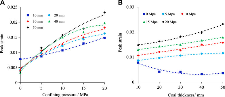
FIGURE 7. Peak Strain of the RCR composites at different inclined coal seam thicknesses and different confining pressures. (A) Influence of different confining pressure; (B) Influence of different coal thickness.
As shown in Figure 7B, when the confining pressure of the composite samples is 0 MPa, the peak strain first decreases rapidly and then remains constant as the inclined coal seam thickness increases. When the confining pressure is between 5 and 20 MPa, the peak strain of the composite samples gradually increases as the inclined coal seam thickness increases.
In summary, the results described above indicate that the confining pressure and inclined coal thickness play a positive role in promoting the peak strain.
Influence of Confining Pressure and Inclined Coal Seam Thickness on the Elastic Modulus of RCR Composite Samples
As shown in Figure 8A, when the confining pressure is less than 5 MPa, the elasticity modulus of the composite samples increases nonlinearly as the confining pressure increases. The smaller the inclined coal seam thickness is, the greater the increase in the elasticity modulus is, and the faster the rate of increase is. When the confining pressure is greater than 5 MPa, the elasticity modulus of the composite samples fluctuate slightly as the confining pressure increases and then gradually stabilizes. This may be because the RCR specimen becomes more homogenous with increased confining pressure.
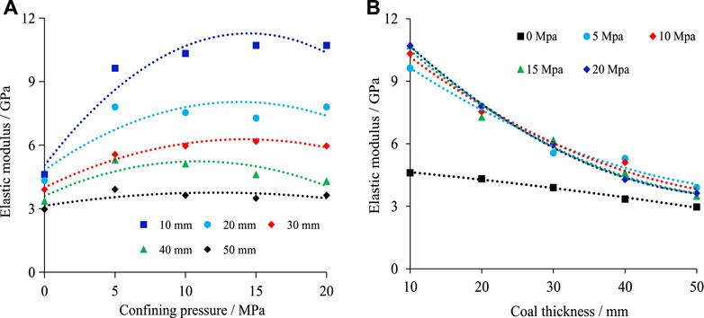
FIGURE 8. Elastic Modulus of the RCR composites at different inclined coal seam thicknesses and different confining pressures. (A) Influence of different confining pressure; (B) Influence of different coal thickness.
As shown in Figure 8B, the elasticity modulus of the composite samples decreases nonlinearly as the inclined coal seam thickness increases. However, as the inclined coal seam thickness increases, the change in the elasticity modulus when the confining pressure is 0 MPa is obviously different from those at other confining pressures, as the magnitude of reduction in the former is smaller and the rate of decrease is also lower. As the ratio of coal increases, the properties of RCR specimen become more similar to the coal specimens, which have lower elastic modulus.
Failure Characteristics and Discussion of RCR Composite Samples at Different Coal Thickness
Influence of Confining Pressure and Coal Thickness on the Number of Cracks in RCR Composite Samples
The influence of confining pressure and inclined coal seam thickness on the failure characteristics of RCR composite samples are shown in Figure 9.
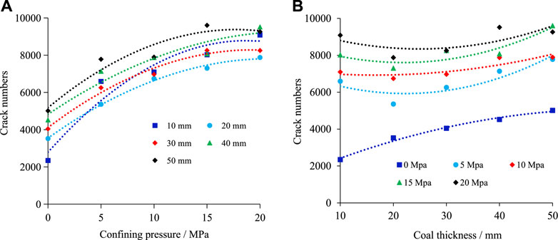
FIGURE 9. Crack number of the RCR composites at different inclined coal seam thicknesses and different confining pressures. (A) Influence of different confining pressure; (B) Influence of different coal thickness.
As can be seen in Figure 9A, the number of cracks in the RCR composite samples shows an overall increasing trend as the confining pressure increases. When the confining pressure is less than 5 MPa (with the exception of the abrupt increase in the number of cracks) at an inclined coal seam thickness of 10 mm, the number of cracks increases slowly when the inclined coal seams are thick. When the confining pressure is greater than 5 MPa, the rate of increase in the number of cracks in the RCR composite samples slows down and gradually tends to stabilize.
From Figure 9B, it can be seen that when the inclined coal seam thickness is less than 20 mm and the confining pressure of the RCR composite samples is 0 MPa, the number of cracks in the RCR composite samples increases as the inclined coal seam thickness increases. When the confining pressure of the RCR composite samples is between 5 and 20 MPa, the number of cracks in the RCR composite samples shows a decreasing trend as the inclined coal seam thickness increases, thus indicating that the confining pressure can inhibit the development of cracks to a certain extent. When the inclined coal seam thickness is greater than 20 mm, the number of cracks in the composite samples increases regardless of the confining pressure, thus indicating that the development of cracks at this time is no longer restrained by the confining pressure.
Failure Characteristics and Discussion of RCR Composite Samples at Different Coal Thicknesses
Figure 10 shows the failure characteristics of the RCR composite samples at different inclined coal seam thicknesses and at different confining pressures.
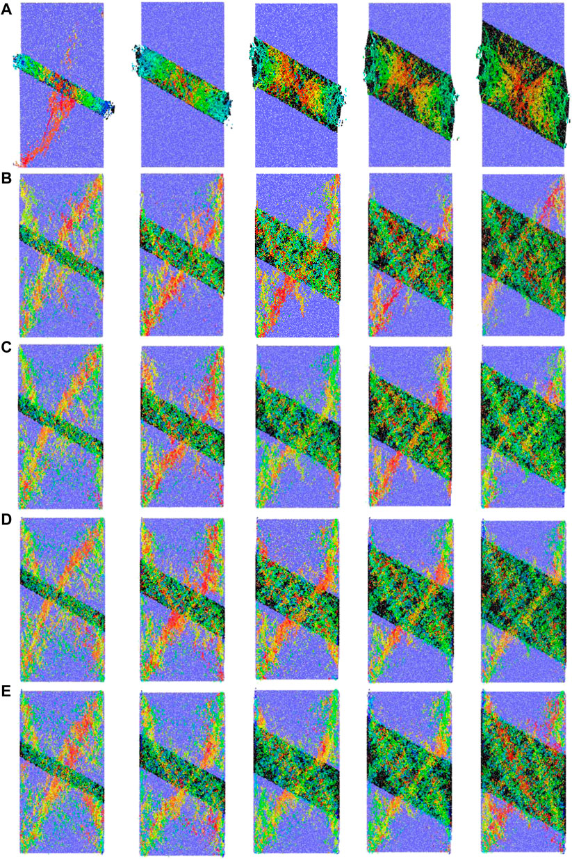
FIGURE 10. Failure characteristics of the RCR composites at different inclined coal seam thicknesses and different confining pressures. (A) σ3= 0 MPa; (B) σ3= 5 MPa. (C) σ3= 10 MPa; (D) σ3= 15 MPa. (E) σ3= 20 MPa
When the confining pressure is 0 MPa, as the inclined coal seam thickness increases [with the exception of the case in which the inclined coal is thin (10 mm)], the RCR composite sample generates relatively few microcracks in the rock section, whereas the coal section experiences failures. Moreover, the thinner the inclined coal seams are, the more serious the damage will be. It can also be observed that when the coal section of the composite samples is damaged, the cracks start from the two ends, gradually expand to the middle section, and finally cover the entire coal section. This shows that during uniaxial compression, the stress concentration occurs at both ends of the coal section first, which is eventually transmitted to the entire coal section. Specifically, when the inclined coal is relatively thin, the overall load-bearing capacity of the coal section is sufficiently high to allow the microcracks to expand through the coal section; microcracks are also generated in the rock section. The strength of the rock section is higher than that of the coal section during uniaxial compression. The latter also has a low strength and low homogeneity. In combination with the angle between the coal and rock sections, the stress concentration of the coal section is much higher than that of the surrounding area, such that failure occurs first in the coal section when subjected to loading. The early failures of RCR composite samples with different inclined coal seam thicknesses all occur in the coal. In the absence of the confining pressure, the composite samples experience mainly the shear failure of the coal. The composite samples experience instability failures even before the ultimate strength of the rock is reached. Therefore, no macroscopic cracks are formed in the rock, and the damage only occurs in the coal section, thus indicating that the failure of the composite samples is mainly caused by the damage of the coal section during uniaxial compression.
When the confining pressure is between 5 and 20 MPa, the failure of the RCR composite samples occurs in both the coal and rock sections as the inclined coal seam thickness increases. The applied confining pressure strengthens the coal section, such that the overall strength of the composite samples is improved considerably, and the failure of the composite samples can be more diversified. The failure process diagrams of all composite samples subjected to triaxial compression reveal that the failure modes can be categorized into two forms: when the confining pressure is low (5 and 10 MPa), the composite sample undergoes Y-shaped failure, and when the confining pressure is high (15 and 20 MPa), the composite sample undergoes X-shaped failure. There are two main reasons for this. First, subject to the action of confining pressure, owing to the high energy stored in the coal section, the energy released when the coal section is destroyed is sufficient to cause the destruction of the rock section, and microcracks are distributed in both the coal and rock sections. However, despite the many randomly distributed microcracks in the coal section, no macrocracks are formed. Additionally, the microcracks in the rock section begin to expand and form areas with a large number of microcracks. Further increases in the loading do not affect the steady development of microcracks in the coal section; however, the microcracks in the rock section develop more rapidly, and continue to grow, develop, and interpenetrate to form macroscopic cracks. Second, when the confining pressure is low, both the coal and the rock sections exhibit shear zones, and the greater the inclined coal seam thickness is, the more obvious the shear zone becomes. However, the length of the shear zone in the coal section is much shorter than that in the rock section, and Y-shaped failure of the composite sample occurs. As the confining pressure increases, the RCR composite samples become increasingly uniform. Therefore, when the confining pressure is large, the length of the shear zone of the coal section gradually increases, and the damage will likely become more symmetrical, thus causing X-shaped failure of the composite sample.
In summary, when the confining pressure is 0 MPa, the early failures of RCR composite samples with different inclined coal seam thicknesses occur in coal, which fail mainly by shear failure. The results indicate that failure of the composite samples is mainly caused by damage of the coal section during uniaxial compression. When the confining pressure is 5–20 MPa, failure of the composite samples can be summarized in two forms: the first occurs when the confining pressure is low (5 and 10 MPa), wherein the composite sample undergoes Y-shaped failure; and the second occurs when the confining pressure is high (15 and 20 MPa), wherein it undergoes X-shaped failure.
Conclusions
The failure characteristics and strength of the RCR composite samples are closely related to the inclined coal seam thickness. At the same confining pressure, the elasticity modulus and peak stress both decrease nonlinearly as the inclined coal seam thickness increases. As the thickness increases, when the confining pressure is 0 MPa, the peak strain first decreases rapidly and then remains constant. By contrast, when the confining pressure is 5–20 MPa, the peak strain increases gradually.
The failure characteristics and strength are also closely related to the confining pressure. Both the elasticity modulus and peak strain of the RCR composite samples increase nonlinearly as the confining pressure increases. When the confining pressure is low, it has a considerable influence on the peak stress of the composite sample; however, when the confining pressure is high, the strength is no longer sensitive to the confining pressure.
When the confining pressure of the RCR composite samples is 0 MPa [with the exception of the case in which the inclined coal seam is thin (10 mm)], there is a small number of microcracks in the rock section; accordingly, the damage only occurs in the coal section. When the confining pressure of the RCR assembly is between 5 and 20 MPa, the failure of the composite samples can be summarized in two forms: the first occurs when the confining pressure is low (5 and 10 MPa), wherein the composite sample undergoes Y-shaped failure; and the second occurs when the confining pressure is high (15 and 20 MPa), wherein the composite sample undergoes X-shaped failure.
Data Availability Statement
The original contributions presented in the study are included in the article/supplementary material, further inquiries can be directed to the corresponding author.
Author Contributions
FW and BM proposed the idea. BM contributed to writing the manuscript. BM and HL contributed to the numerical simulation. BM, DY, and ZX contributed to analyzing the data. All authors contributed to the article and approved the submitted version.
Funding
This research is supported by the National Natural Science Foundation of China (51904162), China Postdoctoral Science Foundation (2020M682208), Postdoctoral Innovation Project of Shandong Province (202102036), SDUST Research Fund (2019TDJH101), Elite talent project of SDUST, State Key Laboratory of Mining Disaster Prevention and Control Co-Founded by Shandong Province and The Ministry of Science and Technology (SICGM202104) and Postdoctoral Researcher Application Research Project of Qingdao, Shandong Province.
Conflict of Interest
The authors declare that the research was conducted in the absence of any commercial or financial relationships that could be construed as a potential conflict of interest.
Publisher’s Note
All claims expressed in this article are solely those of the authors and do not necessarily represent those of their affiliated organizations, or those of the publisher, the editors and the reviewers. Any product that may be evaluated in this article, or claim that may be made by its manufacturer, is not guaranteed or endorsed by the publisher.
References
1. Wang SL, Hao SP, Chen Y, Bai JB, Wang XY, Xu Y. Numerical Investigation of Coal Pillar Failure under Simultaneous Static and Dynamic Loading. Int J Rock Mech Mining Sci (2016) 84:59–68. doi:10.1016/j.ijrmms.2016.01.017
2. Gao R, Yan H, Ju F, Mei X, Wang X. Influential Factors and Control of Water Inrush in a Coal Seam as the Main Aquifer. Int J Mining Sci Tech (2018) 28:187–93. doi:10.1016/j.ijmst.2017.12.017
3. Wang F, Jiang BY, Chen SJ, Ren MZ. Surface Collapse Control under Thick Unconsolidated Layers by Backfilling Strip Mining in Coal Mines. Int J Rock Mech Mining Sci (2019) 113:268–77. doi:10.1016/j.ijrmms.2018.11.006
4. Wang F, Xu JL, Xie JL. Effects of Arch Structure in Unconsolidated Layers on Fracture and Failure of Overlying Strata. Int J Rock Mech Mining Sci (2019) 114:141–52. doi:10.1016/j.ijrmms.2018.12.016
5. Abiodun L, Sangki K, Olaide SH, Musa AI. Blast-Induced Ground Vibration Prediction in Granite Quarries: An Application of Gene Expression Programming, ANFIS, and Sine Cosine Algorithm Optimized ANN. Int J Mining Sci Tech (2021) 31:265–77. doi:10.1016/j.ijmst.2021.01.007
6. Wang P, Jia H, Zheng P. Sensitivity Analysis of Bursting Liability for Different Coal-Rock Combinations Based on Their Inhomogeneous Characteristics. Geomatics, Nat Hazards Risk (2020) 11:149–59. doi:10.1080/19475705.2020.1714754
7. Li QH, Li JK, Wang ZQ, Li KX, Zhang CZ. Study on Coal Pillar Size Design Based on Non-integral Contact Structure of Coal and Rock under Static and Dynamic Loads. Front Mater (2021) 8:721713. doi:10.3389/fmats.2021.721713
8. Petukhov IM, Linkov AM. The Theory of Post-Failure Deformations and the Problem of Stability in Rock Mechanics. Int J Rock Mech Mining Sci Geomechanics Abstr (1979) 16:57–76. doi:10.1016/0148-9062(79)91444-X
9. Guo DM, Zuo JP, Zhang Y, Yang RS. Research on Strength and Failure Mechanism of Deep Coal-Rock Combination Bodies of Different Inclined Angles. Chin Rock Soil Mech (2011) 32:1333–9. doi:10.16285/j.rsm.2011.05.029
10. Huang BX, Liu JW. The Effect of Loading Rate on the Behavior of Samples Composed of Coal and Rock. Int J Rock Mech Mining Sci (2013) 61:23–30. doi:10.1016/j.ijrmms.2013.02.002
11. Liu J, Wang EY, Song DZ, Wang SH, Niu Y. Effect of Rock Strength on Failure Mode and Mechanical Behavior of Composite Samples. Arab J Geosci (2015) 8:4527–39. doi:10.1007/s12517-014-1574-9
12. Chen SJ, Yin DW, Zhang BL, Ma HF, Liu XQ. Mechanical Characteristics and Progressive Failure Mechanism of Roof-Coal Pillar Structure. Chin J Rock Mech Eng (2017) 36:1588–98. doi:10.13722/j.cnki.jrme.2016.1282
13. Xie ZZ, Zhang N, Meng FF, Han CL, An YP, Zhu RJ. Deformation Field Evolution and Failure Mechanisms of Coal-Rock Combination Based on the Digital Speckle Correlation Method. Energies (2019) 12:2511. doi:10.3390/en12132511
14. Wang T, Ma ZG, Gong P, Li N. Analysis of Failure Characteristics and Strength Criterion of Coal-Rock Combined Body with Different Height Ratios. Adv Civil Eng (2020) 2020:1–14. doi:10.1155/2020/8842206
15. Tan YL, Liu XS, Shen B, Ning JG, Gu QH. New Approaches to Testing and Evaluating the Impact Capability of Coal Seam with Hard Roof And/or Floor in Coal Mines. Geomech Eng (2018) 14:367–76. doi:10.12989/gae.2018.14.4.367
16. Wu GS, Yu WJ, Zuo JP, Du SH. Experimental and Theoretical Investigation on Mechanisms Performance of the Rock-Coal-Bolt (RCB) Composite System. Int J Mining Sci Tech (2020) 30:759–68. doi:10.1016/j.ijmst.2020.08.002
17. Zuo JP, Pei JL, Liu JF, Peng RD, Li YC. Investigation on Acoustic Emission Behavior and its Time-Space Evolution Mechanism in Failure Process of Coal−Rock Combined Body. Chin J Rock Mech Eng (2011) 30:1564–70. doi:10.1631/jzus.B1000185
18. Zhang ZT, Liu JF, Wang L, Yang HT, Zuo JP. Effects of Combination Mode on Mechanical Properties and Failure Characteristics of the Coal−Rock Combinations. J China Coal Soc (2012) 37:1677–81. doi:10.1007/s11783-011-0280-z
19. Liu CL, Tan ZX, Deng KZ, Li PX. Synergistic Instability of Coal Pillar and Roof System and Filling Method Based on Plate Model. Int J Mining Sci Tech (2013) 23:145–9. doi:10.1016/j.ijmst.2013.03.005
20. Li XL, Kang LJ, Li HY, Ouyang ZH. Three-Dimensional Numerical Simulation of Bust-Prone Experiments about Coal-Rock Combination. J China Coal Soc (2012) 36:2064–7. doi:10.1007/s12583-011-0163-z
21. Zhao SK, Zhang Y, Han RJ, Jiang HJ, Zhang NB, Xu ZJ. Numerical Simulation Experiments on Bursting Liability Evolution of Compound Coal-Rock Structure. Nat Sci (2013) 32:1441–6. Chinese Journal of Liaoning Technical University. doi:10.13225/j.cnki.jccs.2011.12.021
22. Guo WY, Zhou H, Xu NH, Chen WG, Wei P. Simulation Study of Mechanical Properties of Coal Rock Combination. Safety in Coal Mines. Adv Civil Eng (2016) 47:33–5. doi:10.13347/j.cnki.mkaq.2016.02.009
23. Zhao YC, Gao MS, He YL, Xu D. Failure Mechanism of a Coal-Rock Combined Body with Inclinations of Structural Planes and a Calculation Model for Impact Energy. Adv Civil Eng (2019) 2019(5):1–18. doi:10.1155/2019/3735427
24. Wu GS, Yu WJ, Zuo JP, Li CY, Du SH Experimental Investigation on Rockburst Behavior of the Rock-Coal-Bolt Specimen under Different Stress Conditions. Sci Rep (2020) 10:7556. doi:10.1038/s41598-020-64513-3
25. Zhang XP, Jiang YJ, Wang G, Wang JC, Wu XZ, Zhang YZ. Numerical Experiments on Rate-dependent Behaviors of Granite Based on Particle Discrete Element Model. Rock Soil Mech (2016) 37:2679–85. doi:10.16285/j.rsm.2016.09.033
26. Wu M, Wang J, Russell A, Cheng Z. DEM Modelling of Mini-Triaxial Test Based on One-To-One Mapping of Sand Particles. Géotechnique (2021) 71:714–27. doi:10.1680/jgeot.19.P.212
27. Wu M, Huang R, Wang J. DEM Simulations of Cemented Sands with a Statistical Representation of Micro-bond Parameters. Powder Tech (2021) 379:96–107. doi:10.1016/j.powtec.2020.10.047
28. Chen SJ, Yin DW, Jiang N, Wang F, Guo WJ. Simulation Study on Effects of Loading Rate on Uniaxial Compression Failure of Combined Rock-Coal Layer. Geomech Eng (2019) 17(4):333e42. doi:10.12989/gae.2019.17.4.333
29. Yin DW, Chen SJ, Chen B, Jiang LS, Meng T, Wang W. Simulation Study on Effects of Coal Persistent Joint on Strength and Failure Characteristics of Rock-Coal Combined Body. J Mining Saf Eng (2018) 35(5):322–38. doi:10.13545/j.cnki.jmse.2018.05.024
30. Wang X, Yuan W, Yan YT, Zhang X. Scale Effect of Mechanical Properties of Jointed Rock Mass: A Numerical Study Based on Particle Flow Code. Geomech Eng (2020) 21:259–68. doi:10.12989/gae.2020.21.3.259
31. Castro-Filgueira U, Alejano LR, Arzúa J, Ivars DM. Sensitivity Analysis of the Micro-parameters Used in a PFC Analysis towards the Mechanical Properties of Rocks. Proced Eng (2017) 191:488–95. doi:10.1016/j.proeng.2017.05.208
Keywords: rock-coal-rock composite, inclined coal seam thickness, confining pressure, particle flow, mechanical properties
Citation: Ma B, Wang F, Liu H, Yin D and Xia Z (2022) Mechanical Properties of Rock–Coal–Rock Composites at Different Inclined Coal Seam Thicknesses. Front. Phys. 9:806055. doi: 10.3389/fphy.2021.806055
Received: 31 October 2021; Accepted: 20 December 2021;
Published: 13 January 2022.
Edited by:
Qingxiang Meng, Hohai University, ChinaReviewed by:
Yingchun Li, Dalian University of Technology, ChinaMengmeng Wu, City University of Hong Kong, Hong Kong SAR, China
Copyright © 2022 Ma, Wang, Liu, Yin and Xia. This is an open-access article distributed under the terms of the Creative Commons Attribution License (CC BY). The use, distribution or reproduction in other forums is permitted, provided the original author(s) and the copyright owner(s) are credited and that the original publication in this journal is cited, in accordance with accepted academic practice. No use, distribution or reproduction is permitted which does not comply with these terms.
*Correspondence: Feng Wang, d2FuZ2ZlbmdAc2R1c3QuZWR1LmNu