 Kequn Zhuo
 Yu Wang
 Yang Wang
 Kai Wen
 Min Liu
 Ying Ma
 Juanjuan Zheng
 Peng Gao
95% of researchers rate our articles as excellent or good
Learn more about the work of our research integrity team to safeguard the quality of each article we publish.
Find out more
BRIEF RESEARCH REPORT article
Front. Phys. , 22 November 2021
Sec. Optics and Photonics
Volume 9 - 2021 | https://doi.org/10.3389/fphy.2021.796935
This article is part of the Research Topic Digital Holography: Techniques and Applications View all 16 articles
This paper presents a partially coherent point-diffraction digital holographic microscopy (PC-pDHM) prototype and demonstrates its application in label-free imaging of the dynamic processes of live cells. In PC-pDHM, the light scattered by a rotating diffuser is coupled into a multi-mode fiber, and the output light is used as the partially coherent illumination (PCI), which reduces the speckle noise significantly in PC-pDHM. A polarization-grating is used to remold the object and the reference waves, and the fringe contrast of the generated hologram can be adjusted by changing the polarization of the illumination wave. Using the PC-pDHM prototype, transparent samples and notably the dynamic processes of live cells were imaged with high contrast and in a label-free manner, discovering the pathological mechanisms of biology in the cellular and sub-cellular levels.
Despite fluorescence microscope allows visualization of live samples with specificity and even with a resolution beyond the diffraction limit [1], sometimes it is also desirable to observe live samples in their natural state [2, 3]. Yet, biological samples are often transparent under visible light, and hence their images have low contrast under conventional light microscopy. Digital holographic microscopy (DHM), being a fast, minimally-invasive imaging technique with intrinsic contrast by exploring the phase of the imaging field, is a label-free, high-contrast image for transparent samples [4, 5]. DHM features a nanometer-ranged axial resolution [6, 7] and autofocusing capability. Nowadays, the reconstruction of DHM can be finished by deep learning frameworks [8], which enhance the performances of DHM in general. So far, DHM has been widely applied to many fields, including industrial inspection [9, 10], biomedical study [11–15], and so on.
Among different types of DHM techniques, point-diffraction digital holographic microscopy (PD-DHM) features high stability against environmental disturbance due to its common-path configuration [16–18]. In PD-DHM, a diffraction grating was used to divide the object wave into two parts, one was still used as the object wave, and the other was converted into a reference wave after being pinhole-filtered on the Fourier plane. Initially, PD-DHM employs an off-axis configuration, which can real-time image samples with a price of reduced spatial-band width product (SBP). In 2010, our group [19] proposed a phase-shifting in-line DPM based on a pair of gratings and later incorporated it with a parallel phase-shifting module for real-time phase imaging [20]. These configurations can maximize the SBP of the camera and provide a higher spatial resolution in the reconstruction. Recently, we proposed a polarization-grating based point-diffraction DHM (PG-DPM), with which the fringe contrast can be adjusted by using a polarization diffraction grating [21]. PG-DPM relies on coherent illumination, and hence its reconstruction suffers from speckle noise, which, in turn, restrict the measurement accuracy for the detection of optical path length changes [22]. Partially coherent light (PCI) sources allow for noise reduction in DHM [23], and offer an increased phase resolution. A wide variety of approaches to generate PCIs were proposed, including the induction of vibrations to a multi-mode optical fiber, the usage of a rotating ground glass-diffuser [23–28], or light emitting diodes (LEDs) [29, 30]. Popescu proposed white-light point-diffraction DHM, which has an enhanced signal-to-noise ratio (SNR) [31]. However, for PD-DHM, a broadly-extended light source (such as LEDs) will broaden the undiffracted component (the dc term) of the object wave, and hence it is difficult to generate a uniform and intense reference wave by pinhole-filtering.
In this paper, we propose a partially coherent point-diffraction DHM (PC-pDHM) prototype, which utilizes a multi-mode fiber for PCI generation and a polarization grating for beam splitting. This device retains the advantages of conventional point-diffraction DHM, i.e., real-time measurement, high stability, and high phase-measurement accuracy. Meanwhile, this prototype has two additional merits. First, the coherent noise is significantly reduced by the PCI generated by a multi-mode fiber that couples the light instantly scattered by a rotating diffuser. Second, the fringe contrast can be adjusted or optimized with the combination of a quarter-wave plate (QW) and a polarization diffraction grating (PG). Moreover, we demonstrate the proposed PC-pDHM by phase imaging of glue interlinkage, ascaris egg, and the dynamic process of live cells.
The schematic diagram of the PC-pDHM system is shown in Figure 1A. A 532-nm solid-state crystal laser (1875-532L, Laserland, Wuhan, China) is used as the illumination source. The diameter of the laser output is 4 mm. A microscope objective MO1 (20X/0.4, Nanjing Yingxing Optical Instrument Co., Ltd., Nanjing, China) focuses the light on a rotating glass diffuser (diffusing angle is 15°), and the scattered light is collimated by a lens L1 (f = 75 mm). The diffuser is fixed on a motor (KN335714, Huatong Electronics, Co., Ltd., China), and is rotated at a speed of around 2000 revolutions per second (RPS). Then, the collimated light is refocused by a lens L2 (f = 75 mm) into a 50 μm-diameter multi-mode fiber (DH-FMM050-FC-1A, Daheng Optics, China). At the other end of the fiber, the output light is collimated by a CCTV lens (f = 12 mm, HM1214MP5, China), yielding a versatile partially coherent illumination (PCI) for the PC-pDHM. The regime of PCI generation lies in the fact that the focused light beam (λ, k1) is transiently scattered by a specific point (with the intex n) on the diffuser, yielding an illumination vector k1-kn on the sample plane. It means that any point on the sample plane experiences time-varying illumination with different propagation vectors (λ1, k1-kn). kn has a spatial dependence of the rotating diffusor, which changes with time. Eventually, being averaged with time, the speckle noise at a point on the sample varied can be suppressed by the superimposing and averaging the time-varying illumination, as is shown in Figure 1C. The spatial coherence of the PCI can be adjusted by translating the diffuser along the optical axis. The spatial coherence is maximized when the rotating diffuser is placed at the focal plane of the telescope system MO1-L1. In our experiment, we set the distance between the diffuser and the focal plane of MO1 to ∼0.3 mm, compromising the spatial coherence of the illumination and the coupling coefficiency of the MMF.
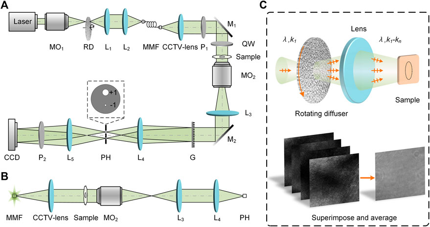
FIGURE 1. Schematic diagram of PC-pDHM. (A) Experimental setup; (B) Relation between the diameters of MMF and PH. (C) The generation of partially coherent illumination (PCI) by using a rotating optical diffuser. CCD, charge-coupled device; G, polarization grating; L1-L5, achromatic lens; M1 and M2, Mirrors; MMF, multi-mode fiber; MO1 and MO2, microscopic objectives; P1-P2, polarizers; PH, pinhole; QW, quarter-wave plate; RD, rotating diffuser.
At the other end of the fiber, the output light is converted by a polarizer P1 into linear polarized light with its polarization along the horizontal direction. And then, the illumination beam, being reflected by the mirror M1, passes through a quarter-wave plate (QW), which turns the illumination light into an elliptically polarized beam. Under such partially coherent illumination (PCI), a sample is imaged by a telescope system consisting of a microscopic objective MO2 (10X/0.45, CFI Plan Apochromat, Nikon, Japan) and a tube lens L3 (f = 150 mm). Consequently, the intermediate image of the sample appears at the back focal plane of the tube lens L3. At this plane, a polarization grating G (#12-677, 159 grooves/mm, Edmund Optics, New Jersey, America) is located and it splits the object wave into different copies along the diffraction orders. Among these, the ±1st diffraction orders have more than 42.5% total energy for each. Of note, the polarization grating has a unique polarization-dependent diffraction characteristic. For instance, the majority of the diffracted intensity will go to the +1st (−1st) order upon the incidence of a left (right) circularly polarized beam. Similar to conventional point-diffraction DHM, in the PC-pDHM system, the +1st order passes through a large hole on the filter mask with its spectrum not being affected, while the −1st order is filtered by a pinhole PH (diameter-50 μm, GCO-P50A, Daheng Optics, Beijing, China) and used as the reference wave, as shown in the inset of Figure 1A. It should be noted that, in PC-pDHM, the pinhole PH has a diameter dPH close to 1 airy unit (AU) and meanwhile dMMF = dPH/M, with M = 1 being the magnification of the imaging system shown in Figure 1B. In this case, the reference wave of PC-pDHM has sufficient intensity, and at the same time, it is uniform in the whole field of view (FOV) of the camera. By contrast, such an ideal reference wave can not be generated by using LEDs for illumination. It is because the emitter of an LED often has a larger diameter, which will, in turn, expand the dc term of the object wave. The generated reference wave either has higher intensity (using a large PH) or uniform intensity distribution (using a small PH), but not the two at the same time.
Before the CCD camera, a linear polarizer P2 with a 45° polarization azimuth is located on the beam path of the object and reference waves to convert the two into the same polarization. The object and reference waves interfere with each other on the plane of a CCD camera (4,000 × 3,000, pixels size 1.85 μm, DMK 33UX226, The Imaging Source Asia Co., Ltd., China). The period of the off-axis hologram generated is 9.6 μm sampled by 5.2 pixels at the CCD plane. The total magnification of the PC-pDHM system is 23× and the theoretical spatial resolution is δ = 0.61λ/NA = 0.72 μm. The exposure time of the camera in these experiments is 30 ms, which can average out all the varying scattering along with the rotating diffuser at 2,000 revolutions per second.
In conventional point-diffraction DHM, the reference wave intensity varies with specific samples, and therefore, the fringe contrast is difficult to maximize. In PC-pDHM, the polarization grating G converts the ±1st orders (the object and reference waves) into elliptically polarized beams with orthogonal principal axes. Consequently, the intensities of the object and reference waves change with the azimuth θ of the QW, i.e., in the form of cos2θ and sin2θ [21]. Therefore, the intensity of the object and reference waves can be balanced by rotating the QW. And eventually, the fringe contrast of the generated hologram can be maximized, which will, in turn, yield a high signal-to-noise ratio (SNR) in the reconstruction.
Assuming that the principal axis azimuth of the QW is θ with respect to the horizontal direction, and the polarization orientation of P2 has an angle of 45° with respect to the horizontal direction, the complex amplitude of the object and reference waves on the camera plane can be expressed as
Here γ1 and γ2 are the constant coefficients, which depend on the diffraction efficiency of the ±1st orders of the polarization grating G and the diameter of the pinhole. It can be inferred from Eq. 1 that the relative intensities of the object and reference waves can be adjusted by rotating the QW. On the CCD plane, the interference of the object and reference waves gives rise to the intensity distribution:
where,
where, FT{·} and IFT{·} represent the Fourier transform and inverse Fourier transform, respectively. A digital reference wave RD = exp(-i
In the first experiment, we demonstrate that the PCI generated by using a rotating diffuser and a multi-mode fiber allows for speckle noise reduction in DHM. A comparison of the uniformity and the speckle noise level between CI and PCI was conducted. In this experiment, the reference wave was blocked, and images were taken for the following two cases: first, using coherent illumination (CI) from a laser coupled and delivered with a single-mode fiber (SMF), and second, using partially coherent illumination (PCI) in virtue of the rotating diffuser and the multi-mode fiber (MMF). Figures 2A,B show the CI and PCI images taken in the absence of any samples in the PC-pDHM system, and Figures 2D,E are the images obtained when using a micro-ruler as the sample. Further, Figures 2C,F show the normalized intensity distributions along the orange/green lines in Figures 2A, B, D, E, respectively. The comparison confirms that the PCI image is more uniform and has a much lower speckle noise. To further quantify the level of speckle noise, the standard deviation (STD) of the intensities within the orange/green boxes (with 150 × 150 pixels) in Figures 2A,B were calculated. The results turn out that the STD is 0.09
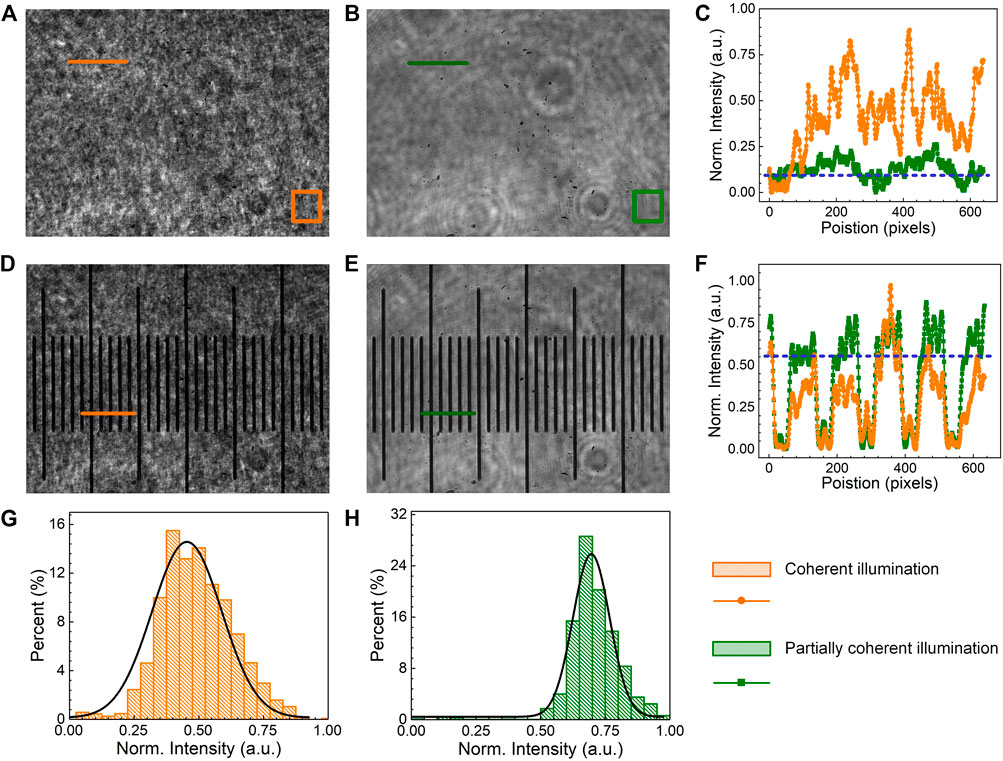
FIGURE 2. The comparison of speckle-noise in CI and PCI. (A,B), the intensity of CI and PCI without samples, respectively. (C) the intensity profiles along the orange/green lines in (A,B). (D,E), the images of a micro-ruler under CI and PCI. (F) intensity profiles along the origin/green solid lines in (D,E). (G,H) are the histograms of the intensity within the orange and green boxes in (A,B).
PC-pDHM has been applied for phase imaging of two static and transparent samples, namely, glue interlinkage of IC devices and ascaris egg slice. As the first sample, glue interlinkage is commonly used in industry, for instance, to connect different integrated circuit (IC) devices. Air bubbles, being one of the mainstream artifacts, often occurs in the glue interlinkage, degrading the interlinkage and hence the performance of IC devices as a whole. Due to the transparency of the glue interlinkage, there is a lack of commercially available instruments to inspect the air bubbles. Here, we demonstrate that PC-pDHM can be a versatile tool to inspect the air bubbles in glue interlinkages. Figure 3A shows an exemplary picture of the glue interlinkage that connects the chip and IC board. Figure 3B shows an off-axis hologram of the glue interlinkage, from which the amplitude and phase images were reconstructed and shown in Figures 3C,D, respectively. The comparison between the amplitude and phase images tells the phase imaging capability of PC-pDHM can visualize air bubbles with higher contrast and in a quantitative manner if the refractive index of the glue is prior-known.

FIGURE 3. Imaging of glue-interlinkage and ascaris egg slice with PC-pDHM. (A–D) The real image, the hologram, the reconstructed amplitude (a.u.), and phase (rad) images of the glue-interlinkage. (E–H) The real image, the hologram, the reconstructed amplitude (a.u.), and phase images (rad) of the ascaris egg slice, respectively. The scale bar in (E), 20 μm.
Second, PC-pDHM was used to image an ascaris egg slice (LIOO Optics, Beijing Jinghao Yongcheng Trading Co., Beijing, China), which was sandwiched between two cover-slips. Figure 3E shows the wide-field image of the ascaris egg under mercury lamp illumination. With PC-pDHM, the amplitude and phase images of the ascaris egg slice were reconstructed from the hologram (Figure 3F), and shown in Figures 3G,H, respectively. The thickness information of the ascaris egg slice missing in the amplitude image due to its transparency. By contrast, quantitative phase distribution (2π/λΔnLl, in term of optical path difference, OPD) of the ascaris egg slice can be visualized in the phase image. The comparison implies that PC-pDHM is capable of extracting fine structures of transparent samples.
In the third experiment, PC-pDHM was used to track one of the vital processes, namely, the fusion of cells without fluorescent labeling. Cell fusion is an important cellular process in which several uninucleate cells (cells with a single nucleus) combine to form a multinucleate cell, known as a syncytium, as is shown in Figure 4I. Cell fusion often occurs during the differentiation of myoblasts, osteoblasts, and trophoblasts, during embryogenesis, and morphogenesis. In this experiment, Cos-7 cells (Q239X mutant in African green monkey kidney cells) were seeded on petri dishes and cultured in high glucose DMEM supplemented with 10% FBS (HyClone) and 1% penicillin-streptomycin (HyClone). Then, the cells were moved to PC-pDHM setup and were imaged continuously for 6 hours. Figure 4A shows one of the recorded off-axis holograms. The frequency spectrum of
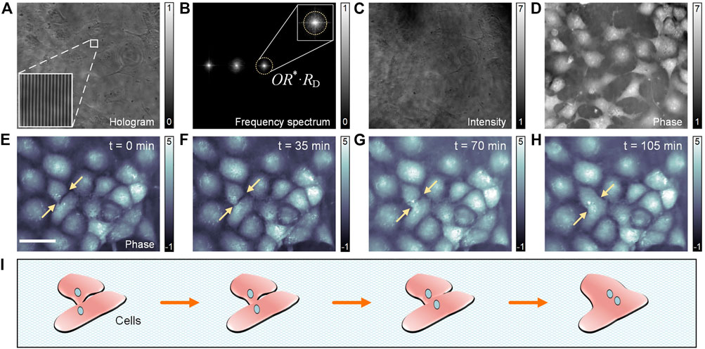
FIGURE 4. Tracking of the fusion process of live cells with PC-pDHM. (A) A PC-pDHM hologram. (B) The spectrum of
To track the fusion process of the live cos-7 cells, the cells were imaged with PC-pDHM continuously for 6 h at a time interval of 20 s. Four phase images at t = 0, 35, 70, and 105 min are shown in Figures 4E–H. In the image series here, the fusion process of two neighboring cells (indicated with two arrows) can be observed with high contrast and in a quantitative manner (for morphology assessment). The whole fusion process from the beginning to the end lasted 105 min. It is worthy to point out that, PC-pDHM can be used to track other vital life processes of cells, such as cell division, apoptosis, attachment, and detachment from surfaces.
In this paper, we proposed a partialy coherent point-diffraction digital holographic microscopy (PC-pDHM) prototype and applied it to imaging transparent samples and dynamic processes of live cells. A partially coherent illumination (PCI) was generated by the combination of a rotating diffuser a multi-mode fiber. A polarization grating is used to diffract the object wave into several copies, and the +1st diffraction orders are used as the object wave and the −1st order as the reference wave after being pinhole-filtered. The relative intensity of the object and reference waves can be freely adjusted by rotating a quarter-wave plate, and therefore, the stripe contrast of the recorded holograms can be maximized. PC-pDHM has the advantages of high stability, high accuracy, low speckle noise, and instant amplitude/phase imaging. Using the proposed PC-pDHM system, we can image transparent samples with high contrast and in a label-free manner. Due to its instant measurement capability, PC-pDHM could be used to track the dynamic process of live cells.
It is also worthy to note that when the PC-pDHM is used to image samples with intrinsic birefringence, the fringe contrast and the measured phase will be influenced by the birefringence. While, on the other side, the birefringence of the sample can be characterized once the phase of the sample is measured with different polarizations of the illumination wave. Another limitation of PC-pDHM is the lack of specificity, and the combination of PC-pDHM with a fluorescence channel will be conducted in the near future.
The original contributions presented in the study are included in the article/Supplementary Material, further inquiries can be directed to the corresponding author.
JZ and PG conceived and supervised the project. KZ, YuW and YaW performed experiments. All the authors contributed to data analysis.
This work was supported by the National Natural Science Foundation of China (NSFC 62075177, 62105251); the Natural Science Foundation of Shaanxi Province (2020JM-193, 2021JQ-184, and 2020JQ-324), the Fundamental Research Funds for the Central Universities (JC2112, XJS210503, XJS210504, and JB210513), Guangdong Basic and Applied Basic Research Foundation (2020A1515110590), and the Open Research Fund of State Key Laboratory of Transient Optics and Photonics and Key Laboratory of Image Processing and Pattern Recognition, Nanchang Hangkong University (ET202080417).
The authors declare that the research was conducted in the absence of any commercial or financial relationships that could be construed as a potential conflict of interest.
All claims expressed in this article are solely those of the authors and do not necessarily represent those of their affiliated organizations, or those of the publisher, the editors and the reviewers. Any product that may be evaluated in this article, or claim that may be made by its manufacturer, is not guaranteed or endorsed by the publisher.
1. Hell SW, Wichmann J. Breaking the Diffraction Resolution Limit by Stimulated Emission: Stimulated-Emission-Depletion Fluorescence Microscopy. Opt Lett (1994) 19:780–2. doi:10.1364/ol.19.000780
2. Li J, Matlock A, Li Y, Chen Q, Zuo C, Tian L. High-speed In Vitro Intensity Diffraction Tomography. Adv Photon (2019) 1:066004. doi:10.1117/1.AP.1.6.066004
3. Zheng C, Jin D, He Y, Lin H, Hu J, Yaqoob Z, et al. High Spatial and Temporal Resolution Synthetic Aperture Phase Microscopy. Adv Photon (2020) 2:065002. doi:10.1117/1.AP.2.6.065002
4. Osten W, Faridian A, Gao P, Körner K, Naik D, Pedrini G, et al. Recent Advances in Digital Holography [Invited]. Appl Opt (2014) 53:G44–G63. doi:10.1364/ao.53.000g44
5. Gao P, Pedrini G, Osten W. Structured Illumination for Resolution Enhancement and Autofocusing in Digital Holographic Microscopy. Opt Lett (2013) 38:1328–30. doi:10.1364/ol.38.001328
6. Kim MK. Principles and Techniques of Digital Holographic Microscopy. J Photon Energ (2010) 1:018005. doi:10.1117/6.0000006
7. Mann CJ, Yu L, Lo C-M, Kim MK. High-resolution Quantitative Phase-Contrast Microscopy by Digital Holography. Opt Express (2005) 13:8693–8. doi:10.1364/opex.13.008693
8. Ren Z, Xu Z, Lam EY. End-to-end Deep Learning Framework for Digital Holographic Reconstruction. Adv Photon (2019) 1:016004. doi:10.1117/1.AP.1.1.016004
9. Emery Y, Cuche E, Marquet F, Aspert N, Marquet P, Kuhn J, et al. Digital Holography Microscopy (DHM): Fast and Robust Systems for Industrial Inspection with Interferometer Resolution. In: Optical Measurement Systems for Industrial Inspection IV. Munich, Germany: International Society for Optics and Photonics (2005).
10. Kebbel V, Hartmann H-J, Jüptner WP. Application of Digital Holographic Microscopy for Inspection of Micro-optical Components. In: Optical Measurement Systems for Industrial Inspection II: Application in Industrial Design. Munich, Germany: International Society for Optics and Photonics (2001).
11. Yamaguchi I, Kato J-i., Ohta S, Mizuno J. Image Formation in Phase-Shifting Digital Holography and Applications to Microscopy. Appl Opt (2001) 40:6177–86. doi:10.1364/ao.40.006177
12. Emery Y, Cuche E, Colomb T, Depeursinge C, Rappaz B, Marquet P et al. DHM (Digital Holography Microscope) for Imaging Cells. J Phys Conf Ser (2007).61, 1317–1321. doi:10.1088/1742-6596/61/1/260
13. Marquet P, Rappaz B, Magistretti PJ, Cuche E, Emery Y, Colomb T, et al. Digital Holographic Microscopy: a Noninvasive Contrast Imaging Technique Allowing Quantitative Visualization of Living Cells with Subwavelength Axial Accuracy. Opt Lett (2005) 30:468–70. doi:10.1364/ol.30.000468
14. Carl D, Kemper B, Wernicke G, von Bally G. Parameter-optimized Digital Holographic Microscope for High-Resolution Living-Cell Analysis. Appl Opt (2004) 43:6536–44. doi:10.1364/ao.43.006536
15. Dubois F, Yourassowsky C, Monnom O, Legros J-C, Debeir O, Van Ham P, et al. Digital Holographic Microscopy for the Three-Dimensional Dynamic Analysis of In Vitro Cancer Cell Migration. J Biomed Opt (2006) 11:054032. doi:10.1117/1.2357174
16. Medecki H, Tejnil E, Goldberg KA, Bokor J. Phase-shifting point Diffraction Interferometer. Opt Lett (1996) 21:1526–8. doi:10.1364/ol.21.001526
17. Naulleau PP, Goldberg KA, Lee SH, Chang C, Attwood D, Bokor J. Extreme-ultraviolet Phase-Shifting point-diffraction Interferometer: a Wave-Front Metrology Tool with Subangstrom Reference-Wave Accuracy. Appl Opt (1999) 38:7252–63. doi:10.1364/ao.38.007252
18. Popescu G, Ikeda T, Dasari RR, Feld MS. Diffraction Phase Microscopy for Quantifying Cell Structure and Dynamics. Opt Lett (2006) 31:775–7. doi:10.1364/ol.31.000775
19. Gao P, Harder I, Nercissian V, Mantel K, Yao B. Phase-shifting point-diffraction Interferometry with Common-Path and In-Line Configuration for Microscopy. Opt Lett (2010) 35:712–4. doi:10.1364/ol.35.000712
20. Gao P, Yao B, Min J, Guo R, Zheng J, Ye T, et al. Parallel Two-step Phase-Shifting point-diffraction Interferometry for Microscopy Based on a Pair of Cube Beamsplitters. Opt Express (2011) 19:1930–5. doi:10.1364/oe.19.001930
21. Zhang M, Ma Y, Wang Y, Wen K, Zheng J, Liu L, et al. Polarization Grating Based on Diffraction Phase Microscopy for Quantitative Phase Imaging of Paramecia. Opt Express (2020) 28:29775–87. doi:10.1364/oe.404289
22. Chavel P. Optical Noise and Temporal Coherence. J Opt Soc Am (1980) 70:935–43. doi:10.1364/josa.70.000935
23. Dubois F, Novella Requena M-L, Minetti C, Monnom O, Istasse E. Partial Spatial Coherence Effects in Digital Holographic Microscopy with a Laser Source. Appl Opt (2004) 43:1131–9. doi:10.1364/ao.43.001131
24. Dubois F, Yourassowsky C, Minetti C, Queeckers P. Benefits of the Spatial Partial Coherence for the Applications in Digital Holography Microscopy. In: Digital Holography and Three-Dimensional Imaging. Washington: Optical Society of America (2010).
25. Dubois F, Callens N, Yourassowsky C, Hoyos M, Kurowski P, Monnom O. Digital Holographic Microscopy with Reduced Spatial Coherence for Three-Dimensional Particle Flow Analysis. Appl Opt (2006) 45:864–71. doi:10.1364/ao.45.000864
26. Stangner T, Zhang H, Dahlberg T, Wiklund K, Andersson M. Step-by-step Guide to Reduce Spatial Coherence of Laser Light Using a Rotating Ground Glass Diffuser. Appl Opt (2017) 56:5427–35. doi:10.1364/ao.56.005427
27. Kumar A, Banerji J, Singh RP. Intensity Correlation Properties of High-Order Optical Vortices Passing through a Rotating Ground-Glass Plate. Opt Lett (2010) 35:3841–3. doi:10.1364/ol.35.003841
28. Wen K, Gao Z, Fang X, Liu M, Zheng J, Ma Y, et al. Structured Illumination Microscopy with Partially Coherent Illumination for Phase and Fluorescent Imaging. Opt Express (2021) 29:33679–93. doi:10.1364/oe.435783
29. Kemper B, Stürwald S, Remmersmann C, Langehanenberg P, von Bally G. Characterisation of Light Emitting Diodes (LEDs) for Application in Digital Holographic Microscopy for Inspection of Micro and Nanostructured Surfaces. Opt Lasers Eng (2008) 46:499–507. doi:10.1016/j.optlaseng.2008.03.007
30. Stürwald S, Kemper B, Remmersmann C, Langehanenberg P, von Bally G. Application of Light Emitting Diodes in Digital Holographic Microscopy. Proc SPIE - Int Soc Opt Eng (2008) 6995:699507. doi:10.1117/12.781186
Keywords: quantitative phase microscopy (QPM), digital holographic microscopy (DHM), point-diffraction, partially coherent illumination, live-cell imaging
Citation: Zhuo K, Wang Y, Wang Y, Wen K, Liu M, Ma Y, Zheng J and Gao P (2021) Partially Coherent Illumination Based Point-Diffraction Digital Holographic Microscopy Study Dynamics of Live Cells. Front. Phys. 9:796935. doi: 10.3389/fphy.2021.796935
Received: 18 October 2021; Accepted: 01 November 2021;
Published: 22 November 2021.
Edited by:
Xiaoyong Hu, Peking University, ChinaReviewed by:
Chao Zuo, Nanjing University of Science and Technology, ChinaCopyright © 2021 Zhuo, Wang, Wang, Wen, Liu, Ma, Zheng and Gao. This is an open-access article distributed under the terms of the Creative Commons Attribution License (CC BY). The use, distribution or reproduction in other forums is permitted, provided the original author(s) and the copyright owner(s) are credited and that the original publication in this journal is cited, in accordance with accepted academic practice. No use, distribution or reproduction is permitted which does not comply with these terms.
*Correspondence: Juanjuan Zheng, amp6aGVuZ0B4aWRpYW4uZWR1LmNu
†These authors have contributed equally to this work
Disclaimer: All claims expressed in this article are solely those of the authors and do not necessarily represent those of their affiliated organizations, or those of the publisher, the editors and the reviewers. Any product that may be evaluated in this article or claim that may be made by its manufacturer is not guaranteed or endorsed by the publisher.
Research integrity at Frontiers
Learn more about the work of our research integrity team to safeguard the quality of each article we publish.