- Department of Electrical and Electronic Engineering, Ariel University, Ariel, Israel
Papers in the literature dealing with the Ethernet network characterize packet delay variation (PDV) as a long-range dependence (LRD) process. Fractional Gaussian noise (fGn) or generalized fraction Gaussian noise (gfGn) belong to the LRD process. This paper proposes a novel clock skew estimator for the IEEE1588v2 applicable for the white-Gaussian, fGn, or gfGn environment. The clock skew estimator does not depend on the unknown asymmetry between the fixed delays in the forward and reverse paths nor on the clock offset between the Master and Slave. In addition, we supply a closed-form-approximated expression for the mean square error (MSE) related to our new proposed clock skew estimator. This expression is a function of the Hurst exponent H, as a function of the parameter a for the gfGn case, as a function of the total sent Sync messages, as a function of the Sync period, and as a function of the PDV variances of the forward and reverse paths. Simulation results confirm that our closed-form-approximated expression for the MSE indeed supplies the performance of our new proposed clock skew estimator efficiently for various values of the Hurst exponent, for the parameter a in gfGn case, for different Sync periods, for various values for the number of Sync periods and for various values for the PDV variances of the forward and reverse paths. Simulation results also show the advantage in the performance of our new proposed clock skew estimator compared to the literature known ML-like estimator (MLLE) that maximizes the likelihood function obtained based on a reduced subset of observations (the first and last timing stamps). This paper also presents designing graphs for the system designer that show the number of the Sync periods needed to get the required clock skew performance (MSE = 10–12). Thus, the system designer can approximately know in advance the total delay or the time the system has to wait until getting the required system’s performance from the MSE point of view.
1 Introduction
Clock synchronization is an essential process in computer networks. This process has to achieve frequency (clock skew) and time (offset or phase) synchronization to ensure that all the components function accurately. There are three significant protocols for time and frequency distribution over the Network: global positioning system (GPS), network time protocol (NTP), and Precision Time Protocol (PTP) Pinchas [1]; Levy and Pinchas [2]; Karthik and Blum [3]. GPS offers frequency and time synchronization accuracy in the sub-microsecond range Levy and Pinchas [2]. However, it requires expensive equipment and routine maintenance Guruswamy et al. [4]. Furthermore, we have a limitation in placing the equipment that communicates with the satellites in certain places Shan et al. [5]; Karthik and Blum [3]. According to Vyas et al. [6]; Peng et al. [7] the GPS also suffers from a weak indoor GPS signal. The NTP is not designed for local area networks (LANs) and has slow response and software clock implementations Levy and Pinchas [2]. Therefore, it can not achieve accurate results compared to the PTP protocol Pinchas [1]. The PTP is defined by the standard IEEE 1588v2 Arnold [8]. It requires minimal Network, computing, and hardware resources Fubin et al. [9]. According to Arnold [8], the PTP is based on a two-way message exchange scheme between the Master and the Slave. By using the two-way message exchange, frequency and time synchronization can be approximately estimated by applying some assumptions. The synchronous Ethernet (SyncE) is a protocol defined by the ITU ITU-T Recommendation [10,11]. It distributes a reference timing signal, where this signal can be extracted, processed, and frequency can be recovered from this signal by the Ethernet equipment clock (EEC) ITU-T Recommendation [10,11]. It should be pointed out that according to Levy and Pinchas [2], the EEC is not available in every system. Generally, the GPS or the SyncE are applied for frequency synchronization, where the PTP protocol and the GPS can be also applied for time or frequency synchronization as well unlike SyncE. The use of PTP for time synchronization is an important step for operations such as managing, securing, planning, and debugging when it is needed to determine the time that events happen Pinchas [1]. The use of PTP for time and frequency synchronization is required in electrical grid networks, cellular base station synchronization, industrial control, communication in financial markets Guruswamy et al. [4]; Karthik and Blum [12] and in Industrial Internet of things (IIoT) Puttnies et al. [13]. The PTP has three different synchronization issues: a.) phase synchronization only, where the PTP protocol is applied for estimating the constant offset. In this scenario, frequency synchronization already exists between the Master and the Slave. b.) Frequency synchronization only, where the PTP is applied for this purpose, while the time (offset) synchronization is not needed here. c.) Time and frequency synchronization is carried out with the PTP protocol. Please note that the offset between the Master and the Slave increases when no frequency synchronization exists between the Master and the Slave.
The PTP uses hardware timestamps traveling between the Master and the Slave nodes Arnold [8], where the path is through several switches and routers. The traveling time in those components determines the duration of the delay in this path. According to Karthik and Blum [12,14,15]; Guruswamy et al. [16] there are two types of delay: a.) the fixed delay, a deterministic propagation delay along the network path, and b.) the random delay, also named as PDV. The PDV is defined as a random variable due to the routers, or the switches behavior ITU-T Recommendation [11]. As mentioned in Karthik and Blum [12] the primary source of the PDV is the output queuing delay, caused when a message arrives at a switch or router and has to wait in a queue due to other traffic that blocked the exit port. The PDV has a major impact on the accuracy obtained with the PTP Sathis Kumar and Kemparaj [17]. Theoretically, PTP can achieve precision of the order of nanoseconds, but, in practice, the PDV causes lower accuracy Puttnies et al. [13]. The queuing delay depends on the load in the network Levy and Pinchas [2]. As the load in the network increases, the PDV may increase accordingly, meaning a higher load may lead to a lower synchronization (time and frequency) accuracy Pinchas [1]. In order to estimate the offset or the clock skew in that scenario, the PTP usually needs more message exchanges between the Master and the Slave, as will be also seen in the simulation results.
The presence of the fixed delay and the PDV cause a problem in estimating the clock skew (frequency) and the offset (time). Due to the behavior of the random delay (PDV), this problem is modeled as a statistical estimation problem Guruswamy et al. [4]. This estimation task is an open issue because we have more unknown variables than number of equations. In order to overcome this problem, the symmetric path between the Master and the Slave is assumed in some algorithms (please refer to Table 1). However, the assumption of a symmetric path may lead to an inaccuracy in the clock skew and offset estimation task, since in practice, this assumption is not valid.
According to Mizrahi [18]; Mizrahi and Moses [19], a correlation exsits between network latency measurements taken at adjacent times. Therefore, the network latency can not be characterized as white noise. In Li and Limb [20]; Peng et al. [21]; Jusak and Harris [22] the PDV is characterized as a Long-Range Dependence (LRD) process. This process can be modeled as a fractional Gaussian noise (fGn) Li and Zhao [23]; Pinchas [1]; Levy and Pinchas [2]; Paxson [24]; Ledesma and Liu [25] or as a generalized fractional Gaussian noise (gfGn) Li [26] (where fGn is a special case of gfGn). Those models (fGn, gfGn) are with Hurst exponent in the range of 0.5 ≤ H < 1, where for H = 0.5 we have the white Gaussian noise. It should be pointed out that we have also the modified multifractional Gaussian noise (mmfGn) Li [27] and the multi-fractional generalized Cauchy process Li [28] for representing a LRD process. But, in this paper we focus on the fGn/gfGn case. The traffic model has a significant impact on the estimation accuracy. Therefore, network traffic models such as the Gaussian or Exponential models may not accurately describe a real network traffic.
On one hand, the PTP is applied for the offset synchronization task only as is done in Pinchas [1], Mizrahi [18,29], Karthik and Blum [14]; Guruswamy et al. [4]; Anand Guruswamy et al. [30]. On the other hand, we may find other algorithms estimating the clock skew and the offset as is done in Levy and Pinchas [2]; Chin and Chen [31], Puttnies et al. [13], Chaudhari et al. [32]; Li and Jeske [33], Noh et al. [34], Guruswamy et al. [4]; Karthik and Blum [12,14,15], Giorgi and Narduzzi [35]. In addition, we may find in the literature algorithms that estimate only the clock skew as is done in Shan et al. [5]; Chaloupka et al. [36]. In this paper, we focus on the clock skew algorithms. In the literature, we can find several approaches estimating the clock skew: 1) The Maximum Likelihood (ML) estimator Levy and Pinchas [2], Karthik and Blum [12]; Guruswamy et al. [4], Chaudhari et al. [32]; Li and Jeske [33]; Noh et al. [34]; Karthik and Blum [11,14]. 2) The Linear Programming estimator Puttnies et al. [13]. 3) The Kalman Filter (KF) estimator Chaloupka et al. [36]; Shan et al. [5]; Giorgi and Narduzzi [35]. Please note that each algorithm used different assumptions, which may also lead to inaccuracy of the clock skew estimator. The authors in Puttnies et al. [13] presented a linear programming estimator that can decrease the influence of the PDV on the synchronization accuracy. However, they assumed that the PDV is Gaussian and that the fixed delay is symmetric between the forward (Master to Slave) and the reverse (Slave to Master) paths. In Chaudhari et al. [32]; Li and Jeske [33] the authors presented an ML estimator where an Exponential model was applied describing the PDV. In addition, they assumed the symmetric path assumption between the forward and reverse paths. In Noh et al. [34] the author suggested first an ML estimator for estimating the clock skew by using the Gaussian and Exponential model for the PDV case. The fixed delay was assumed to be known in this algorithm, which is often an unknown parameter. Therefore, the author presented another algorithm that does not depend on the knowledge of the fixed delay. Still, these algorithms presented in Noh et al. [34] are suitable only for the Gaussian or for the Exponential case. In Levy and Pinchas [2] the authors proposed an ML estimator for estimating the clock skew and the offset in the presence of asymmetric paths and where the PDV was modeled as fGn. This method Levy and Pinchas [2] is based on the dual slave clocks in a slave presented by Chin and Chen [31]. However, Kim [37] demonstrated that the algorithm in Chin and Chen [31] is unusable in practical cases. In Giorgi and Narduzzi [35] the authors presented KF equations with symmetrical paths assumption. The measurement uncertainty in Kalman’s equations gives the solution to the asymmetric forward and the reverse paths. According to Giorgi and Narduzzi [35], the uncertainty was taken in a range of 0.1–100 micro seconds. However, in practice, the asymmetry between the paths can be greater than the given range, so that the clock skew simulation results may be less accurate for that scenario. In addition, this algorithm Giorgi and Narduzzi [35] applies the Gaussian model for the PDV. In Chaloupka et al. [36] the authors used the One Way Mode (OWM) to avoid the asymmetric path problem. Based on simulation results demonstrated in Chaloupka et al. [36], the clock skew estimator achieves relative accurate results only after we wait for a relative long time which in practical cases we can not always afford. The authors in Shan et al. [5] applied KF combined with Sliding Mode Controller (SMC) in order to get better accuracy. Also here, the algorithm assumes symmetrical paths and a Gaussian model for describing the PDV. In Karthik and Blum [12,15]; Guruswamy et al. [4] the authors presented an innovative estimator for the clock skew and for the offset between the Master and the Slave. In Guruswamy et al. [4] the authors presented first their joint estimator, the MINIMAX algorithm, that minimizes the maximum mean squared error of all the unknown parameters. This algorithm assumes that the fixed delays from the Master to Slave and Slave to Master are known, or at least, the difference between them is known. In Karthik and Blum [15] the authors assumed complete knowledge of the statistical information describing the PDV. Recently Karthik and Blum [12], an algorithm was proposed for estimating both the offset and the clock skew in the presence of unknown asymmetric paths, named as the Space Alternating Generalized Expectation-Maximization (SAGE) algorithm. This algorithm assumed a Gaussian Mixture Model (GMM) for the PDV. In estimating the clock skew and the offset according to Karthik and Blum [12], the assumption of having more than only one Master-Slave path was applied (assumption of having multiple Masters). In addition, half of the paths have to be symmetric. Please note that this method Karthik and Blum [12] may be overqualified for applications requiring only clock skew estimation, since Karthik and Blum [12] needs the calculation of the offset estimator for carrying out the clock skew estimator. Thus, the offset estimator can not be shut down when calculating the clock skew estimator. The authors in Karthik and Blum [12] also presented an expression for the Cramer-Rao lower bound (CRLB). This expression (CRLB) is based on the knowledge of which of the multiple masters to the slave paths are considered as asymmetric (where the fixed delays in the Master-Slave and Slave-Master are asymmetric) and on the knowledge of the probability density function (PDF) of the random queuing delays of those paths. Please refer to Table 1 that summarizes the different clock skew algorithms (described earlier in this section), with their assumptions.
In this paper, we propose a novel clock skew estimator based on PTP in an fGn/gfGn environment with Hurst exponent in the range of 0.5 ≤ H < 1 that does not depend on the unknown asymmetry between the fixed path delays in the forward and reverse directions nor on the clock offset between the Master and Slave. We supply a closed-form-approximated expression for the performance (MSE) related to our new proposed clock skew estimator. This closed-form-approximated expression is a function of the Hurst exponent H, as a function of the parameter a for gfGn, as a function of the number of total PTP messages exchanges used in the system for synchronization, as a function of the period between the messages and as a function of the PDV variances in the forward and reverse directions. In addition, we supply designing graphs for the system designer that show the number of PTP messages exchanges needed in the network to get the required clock skew performance as a function of the network parameters (Hurst exponent, parameter a in gfGn and variances of the forward and reverse directions PDV), for the rates of PTP messages exchanges of 64 packets/sec, 16 packets/sec and 8 packets/sec. Simulation results confirm that our closed-form-approximated expression for the MSE related to our new proposed clock skew estimator indeed supplies efficiently the performance of our new proposed estimator for various values of the Hurst exponent, for the parameter a in gfGn, for different periods between the messages, for various values for the number of PTP messages exchanges and for various values for the variances of the PDV in the forward and reverse directions. Simulation results also show the advantage in performance of our new proposed clock skew estimator for various values of the Hurst exponent compared to the literature known ML-like estimator (MLLE) Noh et al. [34] that maximizes the likelihood function obtained based on a reduced subset of observations (the first and last timing stamps). In addition, simulation results will also show the advantage in performance of our new proposed clock skew estimator compared to the maximum likelihood clock skew estimator proposed by Levy and Pinchas [2] and compared to the Kalman clock skew estimator given by Chaloupka et al. [36].
The paper is organized as follows. In Section 2, we briefly introduce the system under consideration and the assumptions we applied for our algorithm. Section 3 proposes the new clock skew estimator and the closed-form approximated expression for the MSE related to our new clock skew estimator. In Section 4, we propose some designing graphs while in Section 5, we present simulation results. Section 6, is our conclusion.
2 System Description
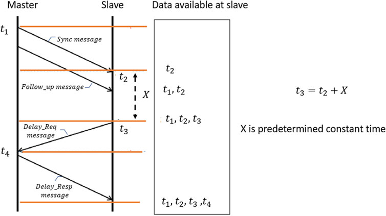
The IEEE 1588v2 is based on the Master-Slave architecture. This protocol distributes information from a Master to its Slave by exchanging messages with timestamps (please refer to Figure 1). The following sequence of steps are performed by the two-way message exchange:
1) The Master initiates the exchange by sending a SYNC message to the Slave at timestamp t1.
2) The Slave receives the SYNC message and keeps the arrival time at timestamp t2.
3) The Master sends the FOLLOW UP message to the Slave with the timestamp t1.
4) The Slave sends back to the Master DELAY REQ message at timestamp t3.
5) The Master receives the DELAY REQ message and keeps the arrival time at timestamp t4.
6) The Master sends the timestamp t4 to the Slave with the DELAY RESP message.
Based on Karthik and Blum [12,14,15] we may write:
where Q is the time difference between the Master and the Slave clocks (offset) and α is the clock skew. The forward and the reverse fixed delays are denoted as dms, dsm respectively and the forward and the reverse PDV are denoted as ω1 [j], ω2 [j] respectively. The total number of the Sync messages periods is denoted as J, where j = 1, 2, 3, … , J.
We consider three different models for the PDV:
1) The PDV is modeled as a white-Gaussian noise with zero mean and the variance
2) The PDV is modeled as an fGn process with zero mean. Based on Li and Zhao [23]; Peng et al. [21] we have:
a. When j = m:
b. When j ≠ m:
3) The PDV is modeled as an gfGn process with zero mean. Based on Li [26] we have:
a. When j = m:
b. When j ≠ m:
In this paper we assume that the forward and reverse PDVs are independent. This assumption is consistent with real systems. Thus, we can write:
3 The Clock Skew Estimator and Its Performance
In this section we present our new clock skew estimator and the closed-form-approximated expression for the MSE related to our new clock skew estimator for three PDV cases: 1. The PDV is a white-Gaussian process, 2. The PDV is an fGn process, 3. The PDV is an gfGn process. At first, we present our new proposed clock skew estimator in Theorem 1. Theorem 2 presents a general closed-form approximated expression for the MSE related to our new clock skew estimator involving the expectation operator on the PDVs. Since the PDV can be one of three cases (a white-Gaussian process, an fGn process and an gfGn process), the MSE from Theorem 2 is further developed for each case. Namely, Theorem 3, Theorem 4 and Theorem 5 are the closed-form approximated expressions for the MSE related to our new clock skew estimator for the white-Gaussian case, fGn case and gfGn case respectively.
3.1 Theorem 1
For the case of t3 [j] − t2 [j] = X, where X is a constant. The clock skew estimator can be defined as:
where
3.1.1 Proof of Theorem 1
In order to avoid the fixed delay, we can subtract between two timestamps from different Sync periods. Based on Eqs 1, 2 we have:
where
and αj,i is the clock skew between the (j + i)-th and ith Sync period.
Based on the summation of Eqs. 5, 6, we can define:
Please note that T3,j(i) = t3 (j + i) − t3(j) is also T3,j(i) = t2 (j + i) + X − (t2(j) + X), meaning that T3,j(i) = T2,j(i). Therefore, αj,i is:
Thus the clock skew can be defined as:
By putting Eq. 9 into Eq. 10 we have:
Now, we can write Eq. 11 as:
Based on Eq. 12 the clock skew estimator is as defined in Eq. 3 and this completes our proof.
3.2 Theorem 2
For the case where
3.2.1 Proof of Theorem 2
Based on Eq. 12 the error is defined as:
According to Eq. 5 we have:
Based on Eq. 15 we may write the expectation of Eq. 14 as:
where aj,i and bj,i are defined as:
For
Based on the assumption made in Section 2, we may write Eq. 18 as:
Now, based on Eq. 19 the approximated MSE related to our new proposed clock skew estimator can be written as:
Next, by recalling the definitions of T1,j(i) and T1,m(k), we can write:
where Tsyn is denoted as the Sync message period.
Based on Eq. 21 we can simplify the expressions in Eq. 20:
Since the PDV has zero mean (please refer to Section 2), Eqs 23, 24 can be set to zero.
Now, by putting Eqs 22, 25, 26 into Eq. 20 we obtain the expression in Eq. 13 and this completes our proof.
In the following, we will calculate the approximated expression for the MSE related to our new proposed clock skew estimator for three different cases:
1) The white-Gaussian case, 2) The fGn case, 3) The gfGn case.
3.3 Theorem 3
The approximate MSE for the white-Gaussian case is:
where P is defined as:
and A and B are given by:
3.3.1 Proof of Theorem 3
In the following, we calculate separately the three different parts in Eq. 13. We start with the first part in Eq. 13. Based on Eq. 7 we can write:
For calculating Eq. 31 we have to consider only five non-zero cases.
The first case is when i = k and m = j. For this case Eq. 31 is:
The second case is when i ≠ k and m = j. For this case Eq. 31 is:
The third case is when m = j + i. For this case Eq. 31 is:
The fourth case is when m = j − k. For this case Eq. 31 is:
The fifth case is when i ≠ k and m = j + i − k. For this case Eq. 31 is:
Based on Eqs 32–36, we may write Eq. 31 as:
Based on Eq. 7 the second part in Eq. 13 can be given as:
The only change in Eq. 38 concerning Eq. 31 is the PDV. Therefore, we can use the calculations we made for the first part. Based on Eq. 37, we can write Eq. 38 as:
The third part in Eq. 13 is:
In order to calculate Eq. 40 we have to consider only six non-zero cases.
The first case is when i = k and m = j. For this case Eq. 40 is:
The second case is when i ≠ k and m = j. For this case Eq. 40 is:
The third case is when m = j + i. For this case Eq. 40 is:
The fourth case is when m = j − k. For this case Eq. 40 is:
The fifth case is when i ≠ k and m = j + i − k. For this case Eq. 40 is:
The sixth case is when m ≠ j and m ≠ j + i and m ≠ j − k and m + k ≠ j + i. For this case Eq. 40 is:
Based on Eqs 41–46, we can write Eq. 40 as:
Now, based on Eqs 37, 39, 47 we may write the approximated MSE related to our new proposed clock skew estimator for the white-Gaussian case as:
In order to calculate the approximated MSE related to our new proposed clock skew estimator, it can be assumed that (1 + α) ≈ 1, because in practical systems, the two clocks (Master and Slave) operate at almost the same frequency. Therefore, Eq. 48 can be rewritten as:
where A and B are defined in Eqs 29, 30 respectively.
Next, we define the correction factor P. This correction factor helps us to calculate the expression for the approximated MSE related to our new proposed clock skew estimator in the fGn and gfGn cases, as will be shown later on.
In the following, we define P as:
We can write Eq. 49 as:
Now, by putting Eq. 50 into Eq. 51 we can write the closed-form approximated expression for the approximated MSE related to our new proposed clock skew estimator as is defined in Eq. 27 and this completes our proof.
3.4 Theorem 4
For the case where the PDV is defined as an fGn process with 0.5 ≤ H < 1, the closed-form approximated expression for the approximated MSE related to our new proposed clock skew estimator is approximately given by:
where C and D are given by:
and the function fGH (.) is:
3.4.1 Proof of Theorem 4
Based on Eq. 7 the two first parts in Eq. 13 can be written as:
For calculating Eq. 56 we have to consider only six non-zero cases.
The two parts in Eq. 56 have the same calculations. Therefore, we present our calculations for the first part that is given by:
The first case is when i = k and m = j. For this case Eq. 57 is:
which can be written also as:
after rearranging Eq. 59:
The second case is when i ≠ k and m = j. For this case Eq. 57 is:
which can be written also as:
after rearranging Eq. 62:
The third case is when m = j + i. For this case Eq. 57 is:
which can be written also as:
after rearranging Eq. 65:
The fourth case is when m = j − k. For this case Eq. 57 is:
which can be written also as:
after rearranging Eq. 68:
The fifth case is when i ≠ k and m = j + i − k. For this case Eq. 57 is:
which can be written also as:
after rearranging Eq. 71:
The sixth case is when m ≠ j and m ≠ j + i and m ≠ j − k and m + k ≠ j + i. For this case Eq. 57 is:
which can be written also as:
Please note that the summation of Eqs 60, 63, 66, 69, 72 can be written as
Now, we can write Eq. 57 as:
Based on Eq. 75 we may write Eq. 56 as:
The third part in Eq. 13 is quite difficult to carry out for the fGn case. Now, looking at Eq. 27 we notice that Eq. 27 consists actually on the sum of the two first parts of Eq. 13 multiplied by the factor
In order to carry out the third part in Eq. 13 for the fGn case, we approximate it based on Eq. 27. In our approximation we simply multiply the expression of
This completes our proof.
3.5 Theorem 5
For the case where the PDV is defined as an gfGn process with 0.5 ≤ H < 1 and 0 < a ≤ 1 the closed-form approximated expression for the MSE related to our new proposed clock skew estimator is given by:
where C* and D* are given by:
and the function
3.5.1 Proof of Theorem 5
As already was shown in Section 2, we have for the fGn process Li and Zhao [23]; Peng et al. [21]:
where n = 1,2.
On the other hand, we have for the gfGn process Li [26]:
Please note that the difference between Eqs 81, 82 is only by the a factor. Thus, we can use Eqs 52–55 for the gfGn case where the function fGH (.) defined in Eq. 55 and used in Eq. 53 to Eq. 54 is substituted by the function
4 Designing Graphs
In this section, we propose some designing graphs for the fGn and gfGn cases. Thus, the designing graphs for the fGn case will be based on Theorem 4 while the designing graph for the gfGn case will be based on Theorem 5. The closed-form approximated expression for the MSE (for the fGn process Eq. 52 and for the gfGn process Eq. 77) is a function of H, a function of Tsyn, a function of the total sent Sync messages, and a function of the PDV variances. It could be very helpful for the system designer if he could approximately know the total sent Sync messages that the system needs in order to receive the system’s requirement such as MSE = 10–12.
Thus in the following, we will try to create some designing graphs that can help the system designer to achieve the system’s requirement of MSE = 10–12.
Based on Eqs 28, 52, 77 we can write the approximated MSE related to our new proposed clock skew estimator as:
where A and B are defined in Eqs 29, 30 respectively. For the fGn case Ct = C Eq. 53 and Dt = D Eq. 54, and for the gfGn case Ct = C* Eq. 78 and Dt = D* Eq. 79.
After arranging Eq. 83 we have:
In order to simplify Eq. 84 we use the following condition:
Thus, for the fGn and gfGn cases, we may write based on Eqs 84, 85:
Based on Eq. 86 we carry out some designing graphs (Figures 2–5) that were obtained for MSE = 10–12 and for three different Tsyn rates:

FIGURE 2. Designing graph for the fGn case. The graph is based on Eq. 86,
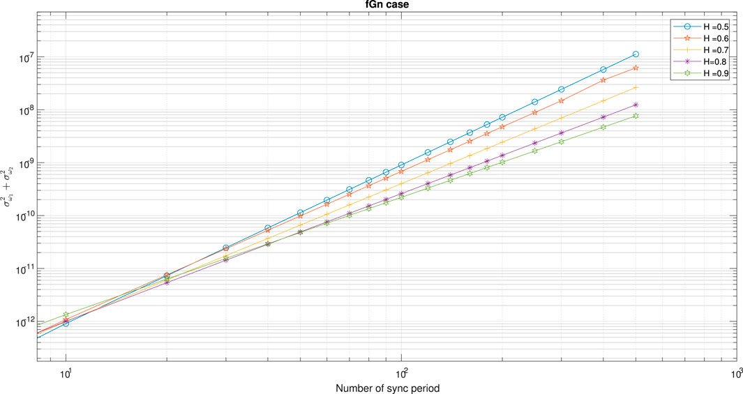
FIGURE 3. Designing graph for the fGn case. The graph is based on Eq. 86,
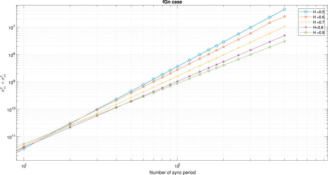
FIGURE 4. Designing graph for the fGn case. The graph is based on Eq. 86,

FIGURE 5. Designing graph for the gfGn case. The graph is based on Eq. 86, E [e2] = 10–12 and H = 0.95.
In order to see if Eq. 85 can actually be ignored, we are going back to the obtained designing graph in Figure 2 to check ourselves.
In the following, we assume that
According to Figure 2, where
1.
2.
3.
According to Figure 2, where
1.
2.
3.
According to Figure 2, where
1.
2.
3.
According to the list from above, we can see that for 10 < J < 500, Eq. 86 is applicable.
5 Simulation Results
In this section, we test our new proposed clock skew estimator Eq. 3 and our closed-form-approximated expression for the MSE for the white-Gaussian Eq. 27, fGn Eq. 52 and gfGn Eq. 77 cases. At first, we show various simulation results in order to show the efficiency of our new proposed clock skew estimator Eq. 3 compared to the ML-like estimator (MLLE) Noh et al. [34] that maximizes the likelihood function obtained based on a reduced subset of observations (the first and last timing stamps). According to Noh et al. [34] we have:
where
T2,1 (J − 1) = t2 [J] − t2 [1], T1,j(i), T2,j(i), T3,j(i) and T4,j(i) are defined in Eqs. 4, 7.
Figure 6 shows the performance comparison between our new proposed clock skew estimator Eq. 3 with the estimator obtained from Noh et al. [34] for the Gaussian case. The results in Figure 6 were obtained for different values for the PDV variances. In addition, we also show there the performance of the new proposed closed-form-approximated expression for the MSE Eq. 27 compared to the simulated one via Eq. 3. According to Figure 6 our new clock skew estimator Eq. 3 achieves a lower MSE compared to the clock skew estimator from Noh et al. [34] for the Gaussian case. In addition, we can clearly see from Figure 6 that our new closed-form-approximated expression for the MSE Eq. 27 supplies results that are very close to the simulated one.
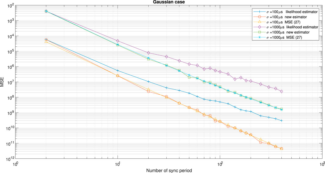
FIGURE 6. Performance comparison between the new clock skew estimator Eq. 3 with the clock skew estimator of Noh et al. [34]denoted here as the likelihood estimator. In addition, we have the simulated performance results for our new proposed expression for the MSE Eq. 27 for the white-Gaussian case. α = 50 ppm, Q = 5 ms,
Figure 7 shows the performance comparison between our new proposed clock skew estimator Eq. 3 with the clock skew estimator obtained from Noh et al. [34] for the fGn case with different values for H. Figure 8 shows the performance comparison between our new proposed clock skew estimator Eq. 3 with the clock skew estimator obtained from Noh et al. [34] for the fGn case with different values for the PDV variances. In addition, we also show in Figures 7, 8 the performance of our new closed-form-approximated expression for the MSE Eq. 52 compared to the simulated one. According to Figures 7, 8 our new clock skew estimator achieves a lower MSE compared to the clock skew estimator from Noh et al. [34] for the fGn case. In addition, we can clearly see from Figures 7, 8 that the performance of our new closed-form-approximated expression for the MSE Eq. 52 is very close to the performance obtained by the simulated MSE.
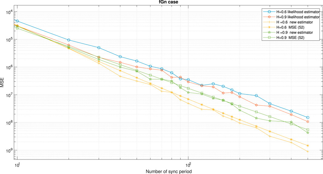
FIGURE 7. Performance comparison between the new clock skew estimator Eq. 3 with the clock skew estimator of Noh et al. [34] denoted here as the likelihood estimator. In addition, we have the simulated performance results for our new proposed expression for the MSE Eq. 52 for the fGn case. α = 50 ppm, Q = 5 ms.
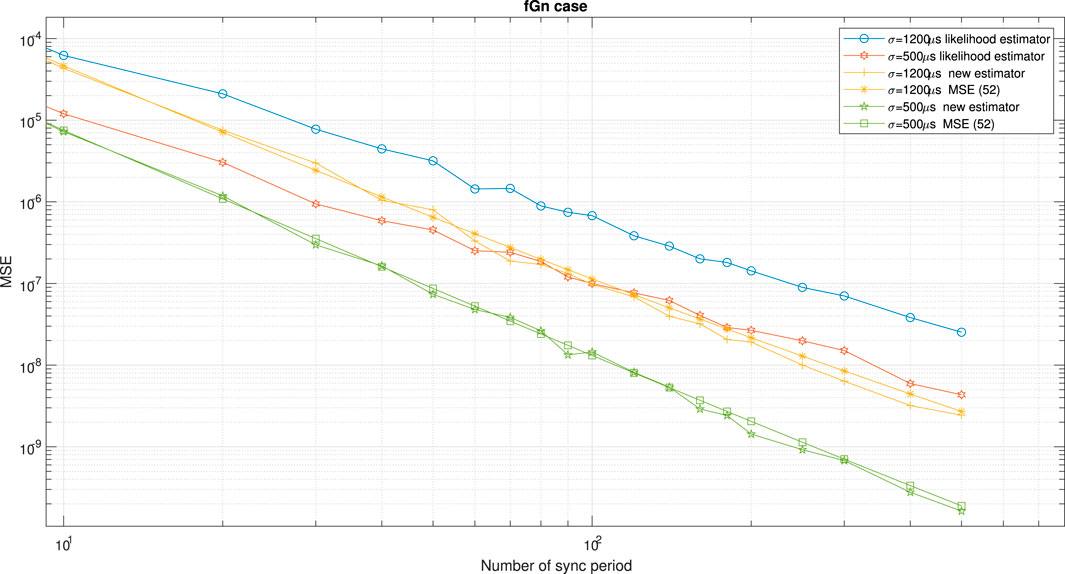
FIGURE 8. Performance comparison between the new clock skew estimator Eq. 3 with the clock skew estimator of Noh et al. [34] denoted here as the likelihood estimator. In addition, we have the simulated performance results for our new proposed expression for the MSE Eq. 52 for the fGn case. α = 50 ppm, Q = 5 ms,
Figure 9 shows the MSE obtained by the new proposed clock skew estimator Eq. 3 compared with our closed-form-approximated expression for the MSE Eq. 52 for the fGn case. The results in Figure 9 were obtained for different forward and reverse PDV variances. According to Figure 9 there is a high correlation between the performance of our closed-form-approximated expression for the MSE Eq. 52 with the simulated MSE.
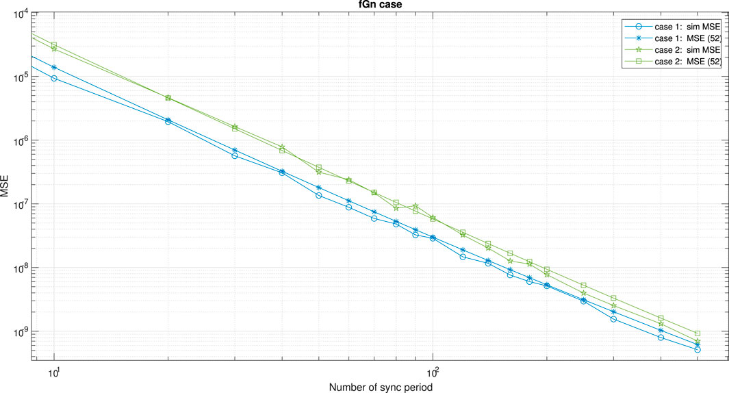
FIGURE 9. Performance comparison between the new proposed expression for the MSE Eq. 52 with those obtained from the simulated clock skew estimator Eq. 3 for the fGn case (denoted here as sim MSE), where the forward and reverse PDV variances are different. α = 50 ppm, Q = 5 ms,
Figure 10 shows the performance comparison between our new proposed clock skew estimator Eq. 3 with the clock skew estimator obtained from Noh et al. [34] for the gfGn case. The results in Figure 10 were obtained for different values of a (please note that we set the values of H and a according to Li [26]). In addition, we also show in Figure 10 the performance of our closed-form-approximated expression for the MSE Eq. 77 compared to the simulated one. According to Figure 10, our new clock skew estimator achieves a lower MSE compared to the clock skew estimator from Noh et al. [34]. In addition, we can see from Figure 10 that the performance of our closed-form-approximated expression for the MSE Eq. 77 is high correlated with the simulated one.
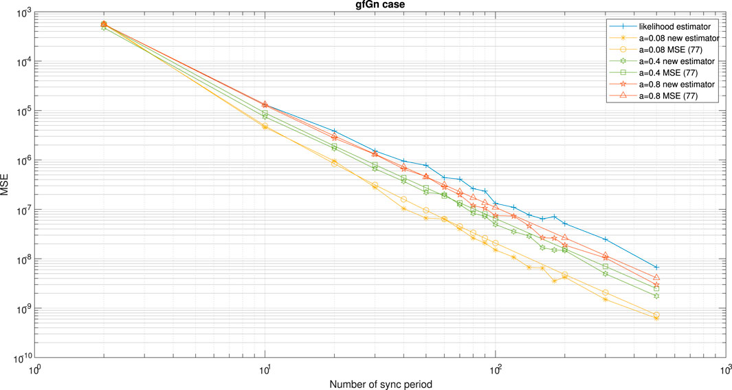
FIGURE 10. Performance comparison between the new clock skew estimator Eq. 3 with the clock skew estimator of Noh et al. [34] denoted here as the likelihood estimator. In addition, we have the simulated performance results for our new proposed expression for the MSE Eq. 77 for the gfGn case. α = 50ppm, Q = 5 ms, Tsyn = 15.6 ms,
It should be pointed out that the clock skew estimator from Noh et al. [34], does not depend on the unknown fixed delay paths nor on the clock offset between the Master and Slave. Thus, it is a good candidate for performance comparison with our new proposed clock skew estimator Eq. 3. Please note that in order to carry out a fair performance comparison, we can only take those clock skew estimators for the simulation performance comparison task, that do not rely on the symmetric assumption for the forward and reverse fixed delay paths as is the case in Puttnies et al. [13], Chaudhari et al. [32], Li and Jeske [33] and Shan et al. [5] (please refer to Table 1). In addition, those clock skew estimators should not rely on multiple Masters or on multiple paths between the Master and Slave as is the case in Karthik and Blum [12]. Thus, based on Table 1, we can use for the simulation performance comparison task also the recently proposed clock skew estimators proposed by Levy and Pinchas [2] and Chaloupka et al. [36]. But, as already was mentioned earlier in this paper, Levy and Pinchas [2] is based on the dual slave clocks in a slave presented by Chin and Chen [31] where Kim [37] demonstrated that the algorithm in Chin and Chen [31] is unusable in practical cases. The clock skew estimator proposed by Chaloupka et al. [36] depends on a predefined parameter L defining the sliding window’s length in the algorithm which has an important role for reaching a low value for the MSE. But, this predefined parameter (L) depends also on the total number of sync periods available for the frequency synchronization task. In other words, the predefined parameter (L) can not be set too large, for example to a value of 1,000 if the available total number of sync periods is only 500. In addition, the noise measurement variance is estimated in Chaloupka et al. [36] involving two smoothing factors which must also be defined in advance.
According to Levy and Pinchas [2] we have:
where Amax (J, i, j, k, H) is:
and
Γ(.) denotes the Gamma function, △ denotes the difference between two consecutive timestamps. Tm.i is the timestamp in the ith period when the Master sends the Sync message. Ts1.i is the timestamp in the ith period when the dual-Slave receives the Sync message. Ts2.i is the timestamp in the ith period when the Slave receives the Sync message.
According to Chaloupka et al. [36] the Kalman’s measurement equation is:
where L is the is the sliding window’s length as defined in Chaloupka et al. [36].
The Kalman’s state equation is:
where the variance of u [j] is QKAL. The estimate of the noise measurement variance is given by Chaloupka et al. [36]:
where
δμ and δμ are smoothing factors which are between zero and one.
Figure 11 shows the performance comparison between our new proposed clock skew estimator Eq. 3 with the clock skew estimator obtained from Noh et al. [34] and Levy and Pinchas [2] for the gfGn case. In addition, we also show in Figure 11 the performance of our closed-form-approximated expression for the MSE Eq. 77 compared to the simulated one. According to Figure 11, our new proposed clock skew estimator achieves a lower MSE compared to the clock skew estimators proposed by Noh et al. [34] and Levy and Pinchas [2].
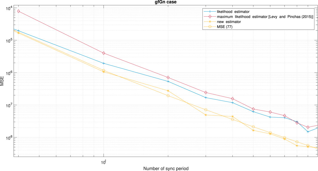
FIGURE 11. Performance comparison between the new clock skew estimator Eq. 3 for the gfGn case with the clock skew estimator of Noh et al. [34] and Levy and Pinchas [2]. The clock skew estimator of Noh et al. [34] is denoted here as the likelihood estimator. We also have the simulated performance results for our new proposed expression for the MSE Eq. 77 for the gfGn case. α = 50 ppm, Q = 5 ms, Tsyn = 15.6 ms,
Figure 12 shows the performance comparison between our new proposed clock skew estimator Eq. 3 with the clock skew estimator obtained from Noh et al. [34] and Chaloupka et al. [36] for the fGn case. According to Figure 12 our new proposed clock skew estimator achieves a lower MSE compared to the clock skew estimators proposed by Noh et al. [34] and Chaloupka et al. [36].

FIGURE 12. Performance comparison between the new clock skew estimator Eq. 3 for the fGn case with the clock skew estimator of Noh et al. [34] and Chaloupka et al. [36]. The clock skew estimator of Noh et al. [34] is denoted here as the likelihood estimator. α = 50 ppm, Q = 5 ms, Tsyn = 15.6 ms,
6 Conclusion
In this paper, we have developed a novel clock skew estimator (applicable for the PTP case) in the presence of asymmetric in the forward and reverse paths. This estimator does not depend on the unknown fixed paths nor on the clock offset between the Master and Slave. Our clock skew estimator does not need multiple Masters nor prior knowledge about the forward and the reverse paths. In addition, we proposed a closed-form approximated expression for the MSE related to our new proposed clock skew estimator. This closed-form approximated expression for the MSE is suitable for the white-Gaussian, fGn, or gfGn environment. Thus, the clock skew estimator and its performance (MSE) are applicable for the long-range dependence environment. It can be seen from the simulation results that the performance of our closed-form approximated expression for the MSE has a high correlation with the performance obtained via the new proposed clock skew estimator. This paper also supplies designing graphs for the system designer that may help the system designer to have approximately the total sent Sync messages to receive the system’s requirement (MSE = 10–12). For a requirement of MSE lower than 10–12, new designing graphs can be easily obtained by Eq. 86. Thus, we have also a closed-form approximated expression Eq. 86 that can help the system designer to figure out the total sent Sync messages needed to get the MSE of any value.
Data Availability Statement
The original contributions presented in the study are included in the article/Supplementary Material, further inquiries can be directed to the corresponding author.
Author Contributions
All authors listed have made a substantial, direct, and intellectual contribution to the work and approved it for publication.
Conflict of Interest
The authors declare that the research was conducted in the absence of any commercial or financial relationships that could be construed as a potential conflict of interest.
Publisher’s Note
All claims expressed in this article are solely those of the authors and do not necessarily represent those of their affiliated organizations, or those of the publisher, the editors and the reviewers. Any product that may be evaluated in this article, or claim that may be made by its manufacturer, is not guaranteed or endorsed by the publisher.
References
1. Pinchas M. Cooperative Multi PTP Slaves for Timing Improvement in an Fgn Environment. IEEE Commun Lett (2018) 22:1366–9. doi:10.1109/lcomm.2018.2830339
2. Levy C, Pinchas M. Maximum Likelihood Estimation of Clock Skew in IEEE 1588 with Fractional Gaussian Noise. Math Probl Eng (2015) 2015:1–24. doi:10.1155/2015/174289
3. Karthik AK, Blum RS. Estimation Theory-Based Robust Phase Offset Determination in Presence of Possible Path Asymmetries. IEEE Trans Commun (2018) 66:1624–35. doi:10.1109/tcomm.2017.2761879
4. Guruswamy A, Blum RSR, Kishore S, Bordogna M. Minimax Optimum Estimators for Phase Synchronization in IEEE 1588. IEEE Trans Commun (2015) 63:3350–62. doi:10.1109/tcomm.2015.2455531
5. Shan F, Yu J, Dong J, Chang X, Yu Z. In: Research on High-accuracy Clock Synchronization Based on IEEE 1588 Protocol; 19-20 Oct. 2019; Dalian, China (2019).
6. Vyas A, Dwivedi S, Gunnarsson F (2018). Improved Precision Time Protocol with Relative Clock Phase Information. In 2018 IEEE International Symposium on Precision Clock Synchronization for Measurement, Control, and Communication (ISPCS). doi:10.1109/ispcs.2018.8543064
7. Peng J, Zhang L, Mclernon D. On the Clock Offset Estimation in an Improved IEEE 1588 Synchronization Scheme. In: European Wireless 2013; 19th European Wireless Conference (2013).
8.[Dataset] Arnold D. In: 1588-2019 - IEEE Standard for a Precision Clock Synchronization Protocol for Networked Measurement and Control Systems. IEEE (2019). Available at: https://standards.ieee.org/standard/1588-2019.html.
9. Fubin P, Yubol Y, Leil G, Liangliang S. The Accuracy of IEEE 1588 Time Synchronization Protocol and its Improvement. In: IEEE 12th International Conference on Electronic Measurement & Instruments (2015). p. 280–4. doi:10.1109/icemi.2015.7494173
10.[Dataset] ITU-T Recommendation. G.8262 : Timing Characteristics of Synchronous Equipment Slave Clock (2018). Available at: https://www.itu.int/rec/T-REC-G.8262 (Accessed October 8, 2020).
11.[Dataset] ITU-T Recommendation. G.8261 : Timing and Synchronization Aspects in Packet Networks (2019). Available at: https://www.itu.int/rec/T-REC-G.8261-201908-I/en (Accessed November 26, 2020).
12. Karthik AK, Blum RS. Robust Clock Skew and Offset Estimation for IEEE 1588 in the Presence of Unexpected Deterministic Path Delay Asymmetries. Ieee Trans Commun (2020) 68:5102–19. doi:10.1109/tcomm.2020.2991212
13. Puttnies H, Danielisx P, Timmermann D. PTP-LP: Using Linear Programming to Increase the Delay Robustness of IEEE 1588 PTP. In: IEEE Global Communications Conference (2018). doi:10.1109/glocom.2018.8647777
14. Karthik AK, Blum RS. Robust Phase Offset Estimation for IEEE 1588 PTP in Electrical Grid Networks. In: 2018 IEEE Power & Energy Society General Meeting (2018). doi:10.1109/pesgm.2018.8586488
15. Karthik AK, Blum RS. Optimum Full Information, Unlimited Complexity, Invariant, and Minimax Clock Skew and Offset Estimators for IEEE 1588. IEEE Trans Commun (2019) 67:3264–637. doi:10.1109/tcomm.2019.2900317
16. Guruswamy A, Blum RSR, Kishore S, Bordogna M. Performance Lower Bounds for Phase Offset Estimation in IEEE 1588 Synchronization. IEEE Trans Commun (2015) 63:243–53. doi:10.1109/tcomm.2014.2371028
17. Sathis Kumar S, Kemparaj P (2019). Enhanced Algorithms for Clock Selection in a Packet Based Synchronization Method. In 2019 IEEE 9th Symposium on Computer Applications & Industrial Electronics (ISCAIE) .doi:10.1109/iscaie.2019.8743747
18. Mizrahi T. Slave Diversity: Using Multiple Paths to Improve the Accuracy of Clock Synchronization Protocols. In: 2012 IEEE International Symposium on Precision Clock Synchronization for Measurement, Control and Communication Proceedings (2012). doi:10.1109/ISPCS.2012.6336621
19. Mizrahi T, Moses Y. On the Behavior of Network Delay in the Cloud. In: 2016 IEEE Conference on Computer Communications Workshops (INFOCOM WKSHPS) (2016). doi:10.1109/infcomw.2016.7562201
20. Li M, Lim SC. Modeling Network Traffic Using Generalized Cauchy Process. Physica A: Stat Mech its Appl (2008) 387:2584–94. doi:10.1016/j.physa.2008.01.026
21. Peng J, Zhang L, Mclernon D. Long-range Dependence and Heavy-Tail Modeling for Teletraffic Data. IEEE Signal Process. Mag (2002) 19:14–27.
22. Jusak J, Harris RJ. Study of Udp-Based Internet Traffic: Long-Range Dependence Characteristics. In: 2011 Australasian Telecommunication Networks and Applications Conference (ATNAC) (2011). doi:10.1109/ATNAC.2011.6096648
23. Li M, Zhao W. On Bandlimitedness and Lag-Limitedness of Fractional Gaussian Noise. Physica A: Stat Mech its Appl (2013) 392:1955–61. doi:10.1016/j.physa.2012.12.035
24. Paxson V. Fast, Approximate Synthesis of Fractional Gaussian Noise for Generating Self-Similar Network Traffic. SIGCOMM Comput Commun Rev (1997) 27:5–18. doi:10.1145/269790.269792
25. Ledesma S, Liu D. Synthesis of Fractional Gaussian Noise Using Linear Approximation for Generating Self-Similar Network Traffic. SIGCOMM Comput Commun Rev (2000) 30:4–17. doi:10.1145/505680.505682
26. Li M. Generalized Fractional Gaussian Noise and its Application to Traffic Modeling. Physica A: Stat Mech its Appl (2021) 579:126138. doi:10.1016/j.physa.2021.126138
27. Li M. Modified Multifractional Gaussian Noise and its Application. Physica Scripta (2021) 96:125002. doi:10.1088/1402-4896/ac1cf6
28. Li M. Multi-fractional Generalized Cauchy Process and its Application to Teletraffic. Physica A (2020) 550:123982. doi:10.1016/j.physa.2019.123982
29. Mizrahi T. A Game Theoretic Analysis of Delay Attacks against Time Synchronization Protocols. In: 2012 IEEE International Symposium on Precision Clock Synchronization for Measurement, Control and Communication Proceedings (2012). doi:10.1109/ISPCS.2012.6336612
30. Guruswamy A, Blum RS, Kishore S, Bordogna M. Performance Lower Bounds for Phase Offset Estimation in IEEE 1588 Synchronization. IEEE Trans Commun (2015) 63:243–53. doi:10.1109/tcomm.2014.2371028
31. Wen-long Chin W-L, Sau-gee Chen S-G. IEEE 1588 Clock Synchronization Using Dual Slave Clocks in a Slave. IEEE Commun Lett (2009) 13:456–8. doi:10.1109/lcomm.2009.090308
32. Chaudhari QM, Serpedin E, Qaraqe K. On Maximum Likelihood Estimation of Clock Offset and Skew Network with Exponential Delays. IEEE Trans Signal Process (2008) 56:1685–97. doi:10.1109/tsp.2007.910536
33. Li J, Jeske DR. Maximum Likelihood Estimators of Clock Offset and Skew under Exponential Delays. Appl Stochastic Models Bus Ind (2009) 25:445–59. doi:10.1002/asmb.777
34. Noh K-L, Chaudhari QM, Serpedin E, Suter BW. Novel Clock Phase Offset and Skew Estimation Using Two-Way Timing Message Exchanges for Wireless Sensor Networks. IEEE Trans Commun (2007) 55:766–77. doi:10.1109/TCOMM.2007.894102
35. Giorgi G, Narduzzi C. Performance Analysis of Kalman-Filter-Based Clock Synchronization in IEEE 1588 Networks. IEEE Trans Instrum Meas (2011) 60:2902–9. doi:10.1109/tim.2011.2113120
36. Chaloupka Z, Alsindi N, Aweya J. Clock Skew Estimation Using Kalman Filter and IEEE 1588v2 PTP for Telecom Networks. IEEE Commun Lett (2015) 19:1181–4. doi:10.1109/lcomm.2015.2427158
37. Kim KS. Comments on “IEEE 1588 Clock Synchronization Using Dual Slave Clocks in a Slave”. IEEE Commun Lett (2014) 18:981–2. doi:10.1109/lcomm.2014.2317738
Keywords: PTP, PDV, LRD, fGn, gfGn
Citation: Avraham Y and Pinchas M (2021) A Novel Clock Skew Estimator and Its Performance for the IEEE 1588v2 (PTP) Case in Fractional Gaussian Noise/Generalized Fractional Gaussian Noise Environment. Front. Phys. 9:796811. doi: 10.3389/fphy.2021.796811
Received: 17 October 2021; Accepted: 10 November 2021;
Published: 22 December 2021.
Edited by:
Ming Li, Zhejiang University, ChinaCopyright © 2021 Avraham and Pinchas. This is an open-access article distributed under the terms of the Creative Commons Attribution License (CC BY). The use, distribution or reproduction in other forums is permitted, provided the original author(s) and the copyright owner(s) are credited and that the original publication in this journal is cited, in accordance with accepted academic practice. No use, distribution or reproduction is permitted which does not comply with these terms.
*Correspondence: Monika Pinchas, bW9uaWthLnBpbmNoYXNAZ21haWwuY29t
 Yehonatan Avraham
 Monika Pinchas
