 Yan Gao1†
 Yanlei Li1†Xin Li1Hongjun Zheng1*Chenglin Bai1Weisheng Hu2
 Hengying Xu1Qiuhuan Dong1Huadong Xing1Yingqun Su1Yingxin Yin1Chongqi Wei1Baiqiang Zhao1
- 1Shandong Provincial Key Laboratory of Optical Communication Science and Technology, School of Physics Science and Information Engineering, Liaocheng University, Liaocheng, China
- 2State Key Laboratory of Advanced Optical Communication Systems Networks, School of Electronic Information and Electrical Engineering, Shanghai Jiao Tong University, Shanghai, China
In this invited paper, a novel elliptical-core few-mode fiber (EFMF) with low loss and low Crosstalk is proposed for multiple input multiple output free (MIMO-FREE) applications. The EFMF, which adopts pure silica elliptical core with a step refractive index profile and trench refractive index, can be used in MIMO-FREE operation. The result using a full-vector finite element method shows that the proposed EFMF breaks the mode degeneracy and achieves modes maintaining function. The EFMF performs five non-degenerate modes operations with the modes LP01, LP11a, LP11b, LP21b, and LP21a for the MIMO-FREE applications. The mode crosstalk of the EFMF is effectively reduced using the optimized ellipticity and the large effective refractive index difference between the modes. If the data rate or capacity is conventionally set to a multiple of 2, the transmission system can be upgraded using the EFMF with four modes operations where the effective refractive index difference between any two modes is more than 2 × 10⁻³. A pure silica core is employed to effectively reduce intrinsic loss. The low bending loss is realized by using the trench refractive index at the cladding. The EFMF can be applied to the good transmission of mode division multiplexing in MIMO-FREE applications while eliminating the difficulty and complexity of the MIMO digital signal processing.
Introduction
With the increasing development of various communication services such as cloud computing, big data, and short video, users have an increasing demand for data transmission capacity or transmission spectral efficiency. The single-mode fiber transmission system has been unable to meet the needs of more and more communication services, because the communication capacity of the single-mode optical fiber has approached the non-linear Shannon limit [1]. The method of mode division multiplexing based on few-mode fibers, which can exponentially increase the transmission capacity or spectral efficiency to meet the demand for unabated growth of data traffic, has attracted wide attention and become a research focus in the field of fiber communication. The research of mode division multiplexing is mainly focused on few-mode fiber (FMF) [2–9], few-mode (de)multiplexer [5–7, 10, 11], few-mode erbium-doped fiber amplifier [12, 13], few-mode fiber transmission system [5–7, 14, 15], etc.
The researches on the few-mode (de)multiplexer, few-mode erbium-doped fiber amplifier, and few-mode fiber transmission system all focus on the main line of the few-mode fiber. The few-mode fiber is the carrier of information transmission in the mode division multiplexing system. Mode division multiplexing based on the few-mode fiber has become one of the research focuses of the next-generation optical communication technology. We will discuss the few-mode fiber in this article. The few-mode fiber generally adopts a circular core with a typical graded refractive index and step refractive index distribution [4]. The mode division multiplexing transmission system based on this kind of few-mode fiber is constantly refreshing the experimental record of spectral efficiency. For instance, the mode division multiplexing transmission based on the three-mode few-mode fiber is proposed [16]. A net capacity of 280 Tbps (93.34 Tbps per mode) and a total spectral efficiency of 29.4 bit/s/Hz are achieved over 30 km few-mode fiber by using 381 WDM channels, three spatial modes, PDM-64QAM modulation format, appropriate mode delay, and 6 × 6 MIMO processing. A mode division multiplexing transmission system based on a weakly coupled 10-mode few-mode fiber is proposed [17]. A capacity record of 257 Tbps and a total spectral efficiency of 30.5 bit/s/Hz are realized over 48 km few-mode fiber by using 336 WDM channels, 10 spatial modes, DP-QPSK modulation format, appropriate mode delay, and 2 × 2 and 4 × 4 partial MIMO processing. In the study mentioned in reference [18], the mode division multiplexing transmission over six-mode graded index few-mode fiber is proposed, where a net capacity of 138 Tbps and the spectral efficiency of 34.91 bit/s/Hz are realized on the loop over 59 km few-mode fiber by using 120 WDM channels, 12 spatial and polarization modes, PDM-16QAM modulation format, appropriate mode delay, and 12 × 12 MIMO processing. It is proposed that a transmission capacity of 266.1 Tbps and a spectral efficiency of 36.7 bit/s/Hz are realized over 90.4 km few-mode fiber by using 580 WDM channels, 19-core 6 spatial modes, DP-64QAM modulation format, appropriate mode delay, and 12 × 12 MIMO processing [19]. The mode division multiplexing transmission based on weakly coupled 10-mode step index few-mode fiber is proposed in the study mentioned in reference [20]. The transmission system with a capacity of 402.7 Tbps and spectrum efficiency of 39.7 bit/s/Hz is realized over 48 km few-mode fiber by using 747 WDM channels, 10 spatial and polarization modes, PS-PDM-16QAM modulation format, appropriate mode delay, and four 4 × 4 MIMO and two 2 × 2 MIMO processing. In the study mentioned in reference [21], mode division multiplexing transmission based on the few-mode fiber with 38 cores and 3 spatial modes is proposed. The net capacity of 10.66 Pbps (93.5 Tbps per mode) and average spectral efficiency of 1158.7 bit/s/Hz are realized over 13 km few-mode fiber by using 368 WDM channels, 138 cores three spatial modes, 64QAM and 256QAM modulation formats, appropriate mode delay, and 6 × 6 MIMO processing.
Although the spectral efficiency of the few-mode fiber transmission system is increased, the circular-core few-mode fiber used in the aforementioned mode division multiplexing system has the problems of mode degeneracy and inter-mode crosstalk. In these circular-core few-mode fibers, linear polarization (LP) modes can be divided into two categories, one is circular symmetrical mode denoted as the LP0m mode, and the other is non-circular symmetrical mode denoted as the LP1m (l > 0) mode. Non-circular symmetric modes have twofold degeneracy such as even mode LP11a and odd mode LP11b. If twofold degeneracy modes such as the modes LP11a and LP11b are used as the two channels of mode division multiplexing at the same time, it is necessary to use appropriate mode delay and 4 × 4 MIMO-DSP receiver to deal with mode degeneracy and polarization diversity, or appropriate mode delay and larger matrix MIMO-DSP receiver to handle more inter-mode crosstalk and mode degeneracy at the same time [16–21]. Mode degeneracy and mode crosstalk need to be handled by using the MIMO-DSP method. The more the modes, the more rapidly the amount of data calculation and complexity increase, which leads to serious problems such as huge power consumption and high cost of short-distance data communication systems [22–24]. In order to solve the aforementioned problems due to mode degeneracy and mode crosstalk in circular-core few-mode fiber, we propose an EFMF with low loss and low crosstalk to break the mode degeneracy and achieve mode maintaining function for the MIMO-FREE applications. The EFMF uses a pure silica core with step refractive index and a trench refractive index profile. The research results show that the EFMF breaks the mode degeneracy and realizes five non-degenerate modes operations including the mode LP01, LP11a, LP11b, LP21b, and LP21a. The EFMF has the advantages of low loss, low crosstalk, and low bending loss, which are obviously better than those in the studies mentioned in Refs. [25–29]. Obviously, our proposed EFMF not only has important applications of MIMO-FREE in the optical communication field, but also can be widely used in the pulse transmission systems [30, 31], high-speed transmission systems [32, 33], sensor systems [34], and fiber laser systems [35, 36]. For example, our proposed EFMF can be applied to the fiber lasers in the reference [36] which can produce two-color laser pulses with narrower linewidth and a higher extinction ratio.
The Design Strategy, Topology Diagram, and Theoretical Model of EFMF
The Main Design Strategy of EFMF
The main purpose of our proposed EFMF is to break the mode degeneracy and realize a mode maintaining function with low crosstalk and low loss for the MIMO-FREE applications, which can effectively solve the serious problems of large delay, large computation, high complexity, huge power consumption, and high cost induced by the MIMO-DSP method in a short-distance communication system based on the conventional circular-core FMF.
These parameters of our proposed EFMF are obtained on the basis of the previous references. First, considering that the radius of the standard single-mode fiber core is about 5 μm in the studies mentioned in Refs. [4, 7] and our proposed fiber core has the major and minor axis radius, we adopt a minor axis radius of 4.6 μm, which is slightly smaller than that of a single-mode fiber. A major axis radius of 6.9 μm and the ellipticity ρ of 1.5 of our proposed EFMF are optimized by that the effective refractive index difference between the modes is as large as possible and the effective area is approximately equal to that of the standard single-mode fiber. This main discussion is described in detail in the section “3.3 Variations of the effective refractive index differences with the ellipticity” in this article.
In this way, that our proposed EFMF breaks the mode degeneracy and realizes the mode-maintaining function with low crosstalk and low loss for the MIMO-FREE applications is achieved by using the optimized ellipticity, a large effective refractive index difference between the modes and pure silica core method. In the case of achieving our goal, other transmission characteristics of our proposed EFMF are also approximately optimized due to the correlation of various parameters, such as effective refractive index difference, effective area, non linear effect, and bending loss. In order to further reduce the bending loss, we use the trench refractive index at the cladding to achieve the lower bending loss.
Design Idea of Bending Loss and Cutoff Mode
The bending loss of our proposed EFMF decreases with an increase of the trench width and bending radius R, as shown in Figure 8A in The Variations of the Bending Losses. However, the trench depth, trench width, and the spacing between the trench and the fiber core, which are comprehensively determined from the studies mentioned in the Refs. [4, 7, 8], are sufficient for our proposed EFMF. For example, a trench width of 10 μm is comprehensively determined from the studies mentioned in the Refs. [4, 7, 8], which is sufficient for our proposed EFMF. This is just an example to show the effect of trench on the bending loss. Of course, we can continue to further optimize the trench. However, too much discussion of the bending loss seems to deviate from our main purpose, so we will not discuss the effect of trench depth and spacing between the trench and the fiber core on the bending loss.
Considering that the span of a practical optical communication application is generally 80 km, the launch power is 0 dBm, and the actual background noise of detection devices such as optical spectrum analyzer is about -60 dBm in general, that one mode transmits over a span of 80 km with the fiber loss of 7.5 × 10⁻⁴ dB/m (i.e., 0.75 dB/km) results in the total fiber loss of 60 dB (60 dB = 0.75 dB/km × 80 km), where the mode will be cutoff and submerged in the background noise due to the mode received power of −60 dBm [37].
There are two evaluation criteria to determine which mode is the cutoff mode and which one is the transmission mode in a fiber [37]. The first criterion is that the fiber loss of a cutoff mode can be higher than the initial threshold value of 7.5 × 10⁻⁴ dB/m (i.e., 0.75 dB/km) for practical optical transmission applications [37]. Here, we can take the fiber loss higher than 7.5 × 10⁻² dB/m at a bending radius of 14 cm used for single mode fibera as a strict evaluation criterion of the cutoff mode, which is hundred times the evaluation standard value of the cutoff mode, as described in the study mentioned in reference [37] for practical application. The second criterion is that the fiber loss of the transmission mode should be smaller than the initial threshold value of 7.5 × 10⁻⁴ dB/m (i.e., 0.0141 dB/100 turns) [37]. Here, we can take the fiber loss lower than 7.5 × 10⁻⁶ dB/m at a bending radius of 30 mm as a strict evaluation criterion of the transmission mode, which is one percent of the evaluation standard value of the transmission mode, as described in the study mentioned in reference [37] for practical optical transmission application.
For our proposed EFMF, the fiber loss includes the intrinsic loss and bending loss. If we take the intrinsic loss of 0.16 dB/km in the C band for calculation, the initial threshold value of bending loss in the evaluation criterion is 0.59 dB/km (0.75 dB/km −0.16 dB/km = 0.59 dB/km, i.e., 5.9 × 10⁻⁴ dB/m). Here, we can take the bending loss higher than 5.9 × 10⁻² dB/m as a strict evaluation criterion of the cutoff mode, which is hundred times the initial threshold value of bending loss of 5.9 × 10⁻⁴ dB/m. We can take the bending loss lower than 5.9 × 10⁻⁶ dB/m as a strict evaluation criterion of the transmission mode, which is one percent of the initial threshold value of 5.9 × 10⁻⁴ dB/m. For our proposed EFMF, the bending loss of the mode LP02 is about 1 dB/m, which is much higher than 5.9 × 10⁻² dB/m at the bending radius of 14 cm, and the bending losses of the modes LP01, LP11a, LP11b, LP21b, and LP21a are all much less than 5.9 × 10⁻⁶ dB/m at a bending radius of 30 mm where those of the higher order modes LP21b and LP21a are about 10−12–10−11 dB/m. According to the two strict criteria from the study mentioned in reference [37], it shows that the modes LP01, LP11a, LP11b, LP21b, and LP21a are the transmission modes in our proposed EFMF, and the mode LP02 is the cutoff mode. Meanwhile, that the lower cutoff wavelength of our proposed EFMF is 1.5 µm and the upper one is 1.8 µm is given in the section “3.9 Cutoff wavelength” in this article.
Topology Diagram and Theoretical Model of EFMF
Figure 1 shows the cross section of the EFMF. The EFMF consists of a pure silica elliptical core with a large refractive index, a trench refractive region, and a cladding. The central coordinate of the core is (0, 0). The shadow area with the horizontal line is the elliptical core of the EFMF, where the major axis radius is ax = 6.9 μm, the minor axis radius is ay = 4.6 μm, and the ellipticity is ρ = ax/ay = 1.5. The shaded elliptical ring with the lower diagonal line is the region of trench refractive index, where the major axis radius of the inner ellipse is bx = 15 μm, the minor axis radius is by = 10 μm, and those of the outer ellipse are, respectively, cx = 30 μm and cy = 20 μm. The rest of the white part is the cladding, and its outer cladding radius is R1 = 62.5 μm. The refractive indexes of the pure silica core, the trench refractive index region, and the cladding are n1 = 1.4440, n2 = 1.4262, and n3 = 1.4303, respectively.
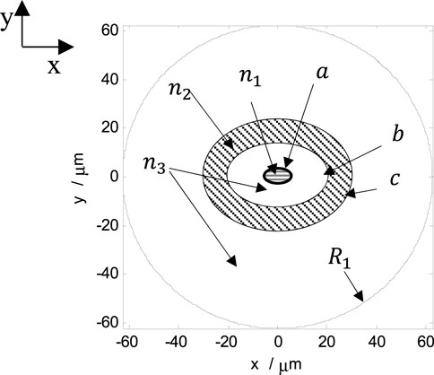
FIGURE 1. Cross section of the EFMF.
We solve the electromagnetic field equation to obtain the electric field vector and the complex effective index using the full-vector finite element method (FEM), and then, the effective refractive index difference of the spatial modes is calculated. Some important parameters such as dispersion, differential mode group delay (DMGD), effective area, non linear coefficient, bending loss, and intrinsic loss are obtained by studying and designing the MATLAB program.
Fiber dispersion is a kind of important physical characteristic that causes transmission signal distortion, which is composed of material dispersion and waveguide dispersion. The dispersion is shown as the variation of refractive index n(ω) with frequency, which can be calculated by using the Sellmeier equation, and the material dispersion can be obtained from the following equation [7, 8, 38, 39]:
where ωj2 is the resonant frequency and Bj is the strength of jth resonance. For silica materials, the corresponding parameters are as follows: m = 3, B1 = 0.6961663, B2 = 0.4079426, B3 = 0.8974794, λ1 = 0.0684043 µm, λ2 = 0.1162414 µm, λ3 = 9.896161 µm, λj = 2πc/ωj, and C is the speed of light in vacuum. The waveguide dispersion can be obtained from the following equation [7, 8, 38, 39]:
where n is the refractive index, C is the speed of light in vacuum, and λ is the wavelength of incident light. DMGD can be obtained from the following equation [38, 39]:
where
and the non linear coefficient is given by the following equation:
where n2 is the non linear refractive index coefficient. ω0 is the central angular frequency of the pulse. The intrinsic loss (αtotal) of our proposed EFMF consists of infrared absorption loss (αIR) and Rayleigh scattering loss (αR) [40].
The Rayleigh scattering loss of optical fiber can be obtained by [40] the following equation:
for pure silica core
for GeO2-doped silica core.where Pcore (r,θ) and Pclad (r,θ) are the mode intensity profiles in the core and the cladding, respectively. A0 = 0.71 (dB/km) (μm4) is the Rayleigh scattering loss coefficient of pure silica fiber.
The B and b of different materials are different.
for pure silica core and
for GeO2-doped silica core.
The bending loss is defined as [41]follow:
where Im(neff) is the imaginary part of the effective refractive index.
Characteristics of Our Proposed EFMF
Electric Field Distribution
Figure 2 shows the X polarization electric field distribution of five non-degenerate modes LP01 (A), LP11a (B), LP11b (C), LP21b (D), and LP21a (E) of our proposed EFMF when the input wavelength is 1.55 μm. We use the notations LP01, LP11a, LP11b, LP21b, and LP21a for the involved modes of the EFMF, due to their mode profiles being similar to those of traditional circular core few-mode fiber (CFMF). Although the mode profile of LP21b in the traditional CFMF shrinks into a profile with three lobes for the EFMF, we still use the notation of LP21b to indicate the corresponding relationship with that of traditional CFMF for ease of comparison investigation. According to the description of the mode-maintaining function of the FMF in the studies mentioned in reference [27, 28], our proposed EFMF obviously performs mode-maintaining operation with five non-degenerate modes LP01, LP11a, LP11b, LP21b, and LP21a.
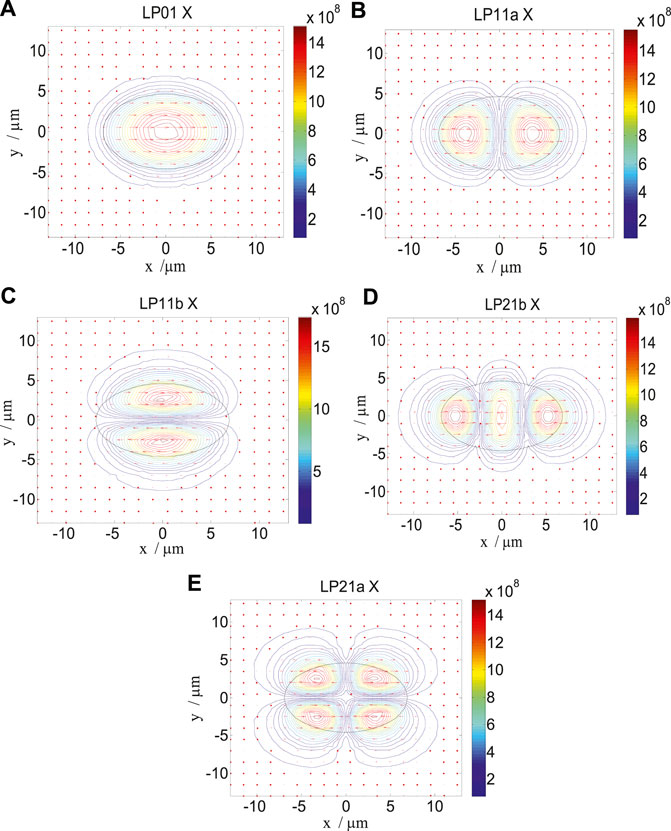
FIGURE 2. Electric field distribution of five non-degenerate modes LP01 (A), LP11a (B), LP11b (C), LP21b (D), and LP21a (E) of our proposed EFMF.
Variations of Effective Refractive Indexes of Spatial Modes
Figure 3 shows the variations of the effective refractive indexes of the five spatial modes with the input wavelength λ. The solid lines with squares, stars, diamonds, circles, and triangles represent the variations of the effective refractive indexes of the modes LP01, LP11a, LP11b, LP21b, and LP21a, respectively. It can be seen from Figure 3 that the effective refractive indexes of the five modes decrease with the increase of input light wavelength, and the variations of effective refractive indexes with the input wavelength are slow.
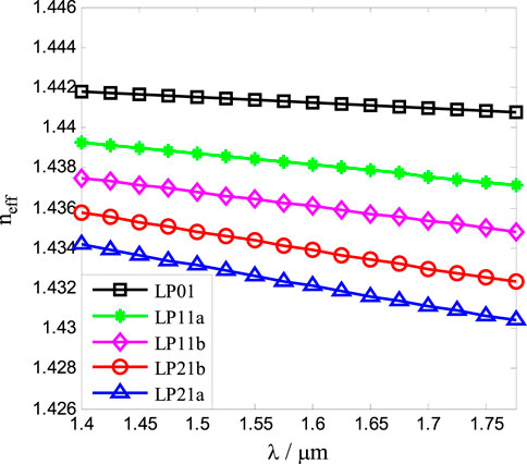
FIGURE 3. Variations of the effective refractive indexes with the input light wavelength. The solid lines with squares, stars, diamonds, circles, and triangles represent the effective refractive indexes of the modes LP01, LP11a, LP11b, LP21b, and LP21a, respectively.
The variation of the effective refractive index of the mode LP01 with the input wavelength is the slowest. The variation of the mode LP21a is the fastest, and that of the modes LP11a, LP11b, and LP21b gradually increases in turn. For a given input wavelength, the effective index neff of the mode LP01 is the largest, that of the mode LP21a is the smallest, and the effective refractive indexes of the modes LP11a, LP11b, and LP21b decrease in turn. When the input wavelength is 1.55 μm, the effective refractive indexes of the modes LP01, LP11a, LP11b, LP21b, and LP21a are 1.4414, 1.4384, 1.4364, 1.4344, and 1.4326, respectively.
Variations of the Effective Refractive Index Differences With the Ellipticity
Figure 4 shows the variations of the effective refractive index differences with the ellipticity ρ at the input wavelength of 1.55 μm. The solid lines with squares, stars, diamonds, circles, and triangles represent the variations of the effective refractive index differences between the modes LP01 and LP11a, LP11a and LP11b, LP11b and LP21b, LP21b and LP21a, and LP21a and cladding, respectively. It can be seen from Figure 4 that the effective refractive index differences between the modes LP01 and LP11a, and LP11b and LP21b decrease with the increase of the ellipticity. However, the effective refractive index differences between the modes LP11a and LP11b, LP21b and LP21a, and LP21a and cladding increase with the increase of the ellipticity. When the ellipticity ρ is about 1.53, a large effective refractive index difference between the modes can be obtained. However, in order to reduce the fabrication error and facilitate the implementation of our proposed EFMF, ρ = 1.5 is selected as the ellipticity of the elliptical core in this study, which makes the effective refractive index differences between the modes larger and reduces the coupling between the modes.
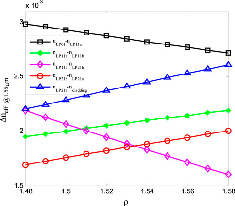
FIGURE 4. Variations of effective refractive index differences with the ellipticity. The solid lines with squares, stars, diamonds, circles, and triangles represent the effective refractive index differences between the modes LP01 and LP11a, LP11a and LP11b, LP11b and LP21b, LP21b and LP21a, and LP21a and cladding, respectively.
When the input wavelength is 1.55 μm and the ellipticity is ρ = 1.5, the effective refractive index difference between the modes LP01 and LP11a is 3.0 × 10⁻³, and those between the modes LP11a and LP11b, LP11b and LP21b, LP21b and LP21a, and LP21a and cladding are, respectively, 2.0 × 10⁻³, 2.1 × 10⁻³, 1.8 × 10⁻³, and 2.3 × 10⁻³. If the data rate or capacity is conventionally set to a multiple of 2, the EFMF transmission system can be upgraded using four non-degenerate modes operation with the modes LP01, LP11a, LP11b, and LP21b, where the effective refractive index difference between any two modes is more than 2.0 × 10⁻³. The index difference between the modes LP11a and LP11b is 2.0 × 10⁻³ in this study, which is 122% larger than that (9 × 10⁻⁴) in the study mentioned in reference [28], and is about 67% larger than that in the study mentioned in reference [27]. In order to minimize mode coupling, the low crosstalk criterion that the effective refractive index difference between any two modes is greater than 0.5 × 10⁻³ (preferably >1.0 × 10⁻³) is proposed in the study mentioned in reference [42]. The low crosstalk between the non-degenerate modes of our proposed EFMF is achieved because the effective refractive index difference between the modes is more obviously greater than the low crosstalk criterion by using the ellipticity ρ = 1.5.
Variations of the Mode Dispersions
Variations of the mode dispersions with the input wavelength λ are shown in Figure 5. Figures 5A–E show the dispersions of the modes LP01, LP11a, LP11b, LP21b, and LP21a, respectively. The solid lines with circles, stars, and triangles represent the material dispersion DM, waveguide dispersion DW, and total dispersion DT of each mode, respectively. From Figure 5A, the waveguide dispersion of the mode LP01 is small, and its variation with the input wavelength is approximately flat in the wavelength range from 1.30 to 1.74 μm. The total dispersion of the mode LP01 increases gradually from 23.79 ps/(nm·km) to 25.93 ps/(nm·km) in the C-band (1.53–1.565 μm). The total dispersion is 25.02 ps/(nm·km) at 1.55 μm.
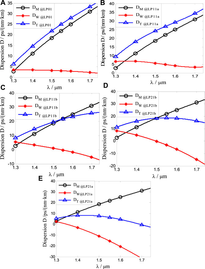
FIGURE 5. Dispersions of the modes LP01 (A), LP11a (B), LP11b (C), LP21b (D), and LP21a (E) vary with the input wavelength. The solid lines with circles, stars, and triangles represent the material dispersion DM, waveguide dispersion DW, and total dispersion DT of each mode.
From Figure 5B, the waveguide dispersion of the mode LP11a decreases gradually, and the total dispersion of the mode LP11a increases gradually in the wavelength range from 1.40 to 1.74 μm. The total dispersion is 26.83 ps/(nm·km) at 1.55 μm.
The waveguide dispersion of the mode LP11b decreases gradually from 5.54 ps/(nm·km) to −7.05 ps/(nm·km) in Figure 5C. The total dispersion of this mode increases gradually in the wavelength range from 1.30 to 1.74 μm, and the increasing rate decreases gradually. The total dispersion is 21.70 ps/(nm·km) at 1.55 μm, and the waveguide dispersion is about 0 at 1.542 μm.
It can be seen from Figure 5D that the waveguide dispersion of the mode LP21b decreases linearly in the wavelength range from 1.30 to 1.74 μm. With the increase of input wavelength, the total dispersion of the mode LP21b is flat in the wavelength range from 1.40 to 1.74 μm. The total dispersion is 18.74 ps/(nm·km) at 1.55 μm.
It can be seen from Figure 5E that the waveguide dispersion of the mode LP21a decreases in the wavelength range from 1.30 to 1.74 μm. The total dispersion increases gradually from 5.34 ps/(nm·km) to 8.38 ps/(nm·km) in the wavelength range from 1.30 to 1.438 μm. The total dispersion gradually decreases from 8.38 ps/(nm·km) to −2.59 ps/(nm·km) in the wavelength range from 1.438 to 1.74 μm. The total dispersion of the mode LP21a is flattened in the wavelength range from 1.30 to 1.60 μm. The total dispersion is 6.39 ps/(nm·km) at 1.55 μm.
Variations of Effective Mode Field Area and Non-Linear Coefficient
Figure 6 shows variations of the effective mode field area Aeff(A) and the non-linear coefficient γ(B) with the incident wavelength. The solid lines with squares, stars, diamonds, circles, and triangles represent the variations of the modes LP01, LP11a, LP11b, LP21b, and LP21a, respectively. As can be seen from Figure 6A, the effective areas of the five non-degenerate modes increase with the increase of input wavelength. For a given input wavelength, the effective area of the mode LP21a is the largest, and those of other four modes are approximately equal to those of the standard single-mode fiber and slightly less than that of the mode LP21a. When the wavelength is 1.55 μm, the effective areas of the modes LP01, LP11a, LP11b, LP21b, and LP21a are, respectively, 73.47, 73.40, 72.31, 78.76, and 89.96 μm2, which are close to the effective area of 80 μm2 of the standard single-mode fiber.
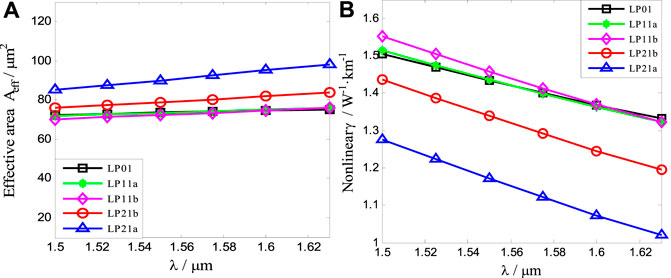
FIGURE 6. Variations of the effective mode field area Aeff (A) and the non-linear coefficient γ (B) with input wavelength. The solid lines with squares, stars, diamonds, circles, and triangles in Figure (A) represent the effective areas of the modes LP01, LP11a, LP11b, LP21b, and LP21a, respectively. The solid lines with squares, stars, diamonds, circles, and triangles in Figure (B) represent the non-linear coefficients of the modes LP01, LP11a, LP11b, LP21b, and LP21a, respectively.
The non-linear coefficients of the five modes all decrease with the increase of input wavelength from Figure 6B. At a given input wavelength, the non-linear coefficient of the mode LP21a is the smallest, which is slightly less than that of other four modes.
Variations of the DMGDs
Figure 7 shows variations of the DMGDs with the input wavelength. The solid lines with stars, diamonds, circles, and triangles represent the DMGDs of the modes LP11a, LP11b, LP21b, and LP21a, respectively. The difference of the DMGDs of the four modes is slightly large.
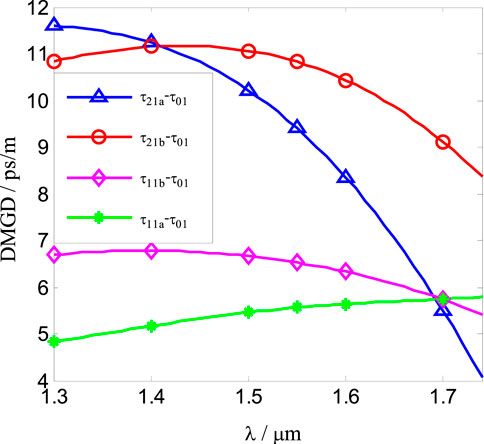
FIGURE 7. Variations of the DMGDs with input wavelength. The solid lines with stars, diamonds, circles, and triangles represent the DMGDs of the modes LP11a, LP11b, LP21b, and LP21a, respectively.
The DMGD of the mode LP11a, which is gradually increased with the increase in the input wavelength, is the most minimum in the wavelength range from 1.30 to 1.68 μm among all DMGDs. The DMGD of the LP21a mode, which is slightly larger than that of the mode LP21b, is much larger than that of the mode LP11b from 1.30 to 1.40 μm. The DMGDs of the modes LP11b, LP21b, and LP21a are all decreased with the input wavelength from 1.40 to 1.68 μm, where the decrease rate of the mode LP21a is the largest, and that of the mode LP11b is the lowest. When the wavelength is 1.55 μm, the DMGDs of the modes LP11a, LP11b, LP21b, and LP21a are, respectively, 5.56, 6.53, 10.82, and 9.40 ps/m.
Variations of the Bending Losses
The bending loss of our proposed EFMF is calculated according to the method of the study mentioned in reference [41]. In order to obtain low bending loss, a trench refractive index region is added to the cladding. Because the bending losses of the modes LP01, LP11a, and LP11b are much smaller than those of the modes LP21b and LP21a, only the bending losses of the modes LP21b and LP21a are studied in this study. Figure 8 shows the variations of the bending losses of the modes LP21a and LP21b.
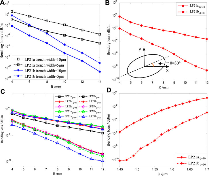
FIGURE 8. When the light wavelength is 1.55 μm, effect of different trench widths on bending loss (A), bending losses of the modes LP21a and LP21b for θ = 30° (B), bending losses of the modes LP21a and LP21b for θ = 0°, 30°, 45°, 60°, 90° (C). Variations of bending losses with the input wavelength for θ = 30° and R = 10 mm (D).
Figure 8A shows the effects of different trench widths on bending loss at 1.55 μm. The solid and dashed lines show the variations of bending losses for the trench width of 10 and 5 μm, respectively. The lines with squares and asterisks represent the variations of bending losses for the modes LP21a and LP21b, respectively. It can be seen from Figure (A) that the bending losses of the modes LP21a and LP21b decrease with the increase of the bending radius R and the trench width.
When the trench width increases from 5 to 10 μm, corresponding to the given bending radius, the bending losses of the modes LP21a and LP21b with trench width of 5 μm are significantly larger than those of the modes LP21a and LP21b with trench width of 10 μm. For the same trench width, the bending loss of the modes LP21a decreases with the increase of R, the variation rate of the modes LP21a with R is less than that of the mode LP21b, and the bending loss of the modes LP21a is larger than that of the mode LP21b for a given R. For R = 10 mm, the bending losses of the modes LP21a and LP21b with trench width of 5 μm are 1.30 × 10⁻² and 7.56 × 10⁻⁶ dB/m, respectively, and the bending losses of the modes LP21a and LP21b with trench width of 10 μm are 1.58 × 10⁻⁴ and 7.34 × 10⁻⁸ dB/m, respectively. The trench width of 10 μm is comprehensively determined from the studies mentioned in Refs. [4, 7, 8], which is sufficient for our proposed EFMF.
The illustration in Figure 8B shows that θ is defined as the angle between the major axis direction of the elliptical core and the bending direction x. The bending losses of the modes LP21a and LP21b are for θ = 30°(B), and those of the modes LP21a and LP21b are for θ= 0°, 30°, 45°, 60°, and 90°, respectively (C). The solid and dashed lines with stars in Figure 8B represent the bending losses of the modes LP21a and LP21b, respectively. The solid lines with squares, stars, diamonds, circles, and triangles in Figure 8C correspond to the bending losses of the mode LP21a for θ = 0°, 30°, 45°, 60°, and 90°, respectively. The dashed lines with squares, stars, diamonds, circles, and triangles in Figure 8C are those of the mode LP21b.
It can be seen from Figure 8B that the bending losses of the modes LP21a and LP21b decrease with the increase of the bending radius for θ = 30°. The decreasing rate of bending loss of the mode LP21a is obviously less than that of the mode LP21b. Corresponding to the given bending radius, the bending loss of the mode LP21a is greater than that of the mode LP21b. When the bending radius of the fiber is 5 mm, the bending losses of the mode LP21a and LP21b are, respectively, 9.28 × 10⁻² and 1.20 × 10⁻³ dB/m. This variation is related to the fact that the refractive index difference between LP21b and cladding is greater than that between LP21a and cladding. As a result, the energy of the mode LP21a is more easily transferred to the cladding than that of the mode LP21b; thus, the bending loss of the mode LP21a is larger.
It can be seen from Figure 8C that the bending losses of the modes LP21a and LP21b decrease with the increase of the bending radius, where the decrease rates are similar to those of Figure 8B. When θ varies from 0° to 90°, the bending loss of the mode LP21a is larger than that of the mode LP21b for a given bending radius. The bending losses of the mode LP21a for θ = 30°, 45°, 60°, and 90°, which are approximately equal, are obviously larger than that of the mode LP21a for θ = 0°. The bending losses of the mode LP21b for θ = 0°, 30°, 45°, and 60°, which are approximately equal, are obviously larger than that of the mode LP21b for θ = 90°.
When the bending radius of the fiber is 10 mm and θ equals to 0°, 30°, 45°, 60°, and 90°, the bending losses of the mode LP21a are 1.58 × 10⁻⁴, 1.00 × 10⁻³, 1.70 × 10⁻³, 1.70 × 10⁻³, and 1.50 × 10⁻³ dB/m, respectively, and those of the modes LP21b are 7.34 × 10⁻⁸, 8.87 × 10⁻⁸, 6.84 × 10⁻⁸, 3.80 × 10⁻⁸, and 2.64 × 10⁻⁹ dB/m, respectively. Our results agree with the bending loss characteristics and satisfy the condition of mode robustness in the study mentioned in reference [43], which shows that the non-degenerate modes of our proposed EFMF have good mode robustness.
For R = 12 mm and θ = 0°, 30°, 45°, 60°, and 90°, the bending losses of the mode LP21b are 2.64 × 10⁻⁹, 3.13 × 10⁻⁹, 2.28 × 10−9,1.08 × 10−9, and 1.26 × 10⁻¹⁰ dB/m, respectively, and those of the mode LP21a are 2.74 × 10⁻⁵, 2.18 × 10⁻⁴, 3.89 × 10⁻⁴, 4.89 × 10⁻⁴, and 1.52 × 10⁻⁴ dB/m, respectively. However, optical fiber is generally wound on a standard size reel with a 25 cm flange diameter or a straight optical cable in transmission applications [44]. In this way, the bending radius of the optical fiber on the spool is more than 125 mm. The large bending radius results in a very small bending loss, which shows that the bending loss of our proposed EFMF is very small and is suitable for the application of optical fiber transmission system.
Since the bending losses for θ = 30° can show the basic characteristics of our proposed EFMF from the previous discussion, we give variations of bending losses with the input wavelength, as shown in Figure 8D for θ = 30° and R = 10 mm. The solid and dashed lines with stars in Figure 8D represent the variations of the bending losses of the modes LP21a and LP21b with the input wavelength, respectively. As can be seen from Figure 8D, the bending losses of the two modes increase with the increase of the input wavelength. The bending losses of the two modes are less than 2.20 × 10⁻¹ dB/m, and the bending loss of the mode LP21a is larger than that of the mode LP21b. At the wavelength of 1.55 μm, the bending losses of the modes LP21a and LP21b are 1.00 × 10⁻³ and 8.88 × 10⁻⁸ dB/m, respectively. Our results are consistent with the bending loss characteristics of the study mentioned in reference [43], which shows that the non-degenerate modes of our proposed EFMF have good mode robustness.
The refractive index of the transmission medium is decreased with the increase of wavelength on the basis of the Sellmeier equation [7, 8]. For a given mode and bending radius, the effective refractive index of the mode also decreases with the increase of wavelength and is closer to the refractive index of the cladding, according to the well-known coordinate transformation formula in the case of the fiber bending [41]. It implies that the energy of the mode is more easily transmitted to the cladding and leaked out with the increase of wavelength. That is to say, the bending loss is increased with the increase of wavelength. However, the bending loss of our proposed fiber wound on the conventional fiber spool is very low, which can be widely used in the practical MIMO-FREE applications.
Intrinsic Loss of Our Proposed EFMF
The intrinsic loss of our proposed EFMF is calculated according to the method in detail in the study mentioned in reference [40]. The trench of the EFMF is ignored in the calculation of the intrinsic loss. The reasons are as follows: The optical power of the mode in our proposed EFMF is mainly concentrated in the fiber core, while the optical power in the trench is so small that it can be ignored. So, the contribution of the trench to the intrinsic loss can be neglected. The trench of our proposed EFMF is not taken into account for the calculation of intrinsic loss.
Figure 9 shows the variations of the intrinsic losses of our proposed EFMF with pure silica core (A) and the conventional FMF with elliptical GeO2-doped core (B) with the input wavelength. The illustrations in Figure 9 show the variations of refractive index profiles with the radius. The solid lines with squares, stars, real dots, circles, and triangles represent the intrinsic losses of the modes LP01, LP11a, LP11b, LP21b, and LP21a with the incident wavelengths, respectively. As can be seen from Figure 9A, the intrinsic loss of the low-order mode is lower than that of the higher order mode of our proposed EFMF. The intrinsic losses of the modes LP01, LP11a, LP11b, LP21b, and LP21a reach the lowest when the input wavelength is 1.53 μm, and the intrinsic losses are 0.1458, 0.1481, 0.1512, 0.1525, and 0.1564 dB/km, respectively. When the wavelength is less than 1.53 μm, the intrinsic losses of the modes increase with the decrease of the wavelength, which are mainly due to the losses caused by the Rayleigh scattering. When the wavelength is greater than 1.53 μm, the intrinsic losses increase with the increase of the wavelength, which are mainly due to the increase of the infrared absorption losses with the increase of the wavelength. In the whole C-band, the intrinsic losses of the five non-degenerate modes of our proposed EFMF are low, which are all less than 0.1595 dB/km. And the intrinsic loss differences between the modes are very small, which is beneficial to signal transmission and detection. From Figure 9B, we can see the variations of the intrinsic losses of the modes LP01, LP11a, LP11b, LP21b, and LP21a of the conventional FMF with elliptical GeO2-doped core. The intrinsic loss of the low-order mode is larger than that of the higher order mode. The lowest intrinsic losses of the modes LP01, LP11a, LP11b, LP21b, and LP21a at 1.55 μm are, respectively, 0.1926, 0.1903, 0.1871, 0.1856, and 0.1815 dB/km, which are 31.65, 28.06, 23.42, 21.31, and 15.75% larger than those of the five modes of our proposed EFMF in Figure 9A. The variations of intrinsic losses with the input wavelength are similar to those of our proposed EFMF.
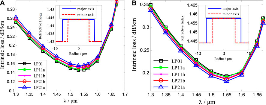
FIGURE 9. Variations of intrinsic losses of our proposed EFMF with pure silica core (A) and the conventional FMF with elliptical GeO2-doped core (B) with the incident wavelength.
By comparing Figure 9A with (B), the intrinsic losses of the two types of optical fibers vary similarly with the input wavelength. However, the intrinsic losses of our proposed EFMF are lower than those of the conventional FMF with an elliptical GeO2-doped core. The intrinsic losses of the modes LP01, LP11a, LP11b, LP21b, and LP21a of our proposed EFMF are increased in turn for a given wavelength, while those of the conventional FMF with elliptical GeO2-doped core are on the contrary. In the conventional FMF with elliptical GeO2-doped core, the intrinsic loss factor of the fiber core is larger than that of the cladding. Therefore, the more concentrated the core energy of GeO2-doped fiber is, the greater the loss is, and the intrinsic losses of the modes LP21a, LP21b, LP11b, LP11a, and LP01 increase in turn. In our proposed EFMF, the intrinsic loss factor of the fiber core is less than that of the cladding. The more the energy is concentrated in the core, the smaller the loss, which leads to the decrease of the intrinsic loss of the modes LP21a, LP21b, LP11b, LP11a, and LP01 in turn.
Cutoff Wavelength
When the refractive index distribution and radius of optical fibers are given, the input wavelength determines the number of propagation modes in optical fibers. When the wavelength is very short, the number of optical fiber modes increases; when the wavelength is very long, the number of optical fiber modes will decrease. The cutoff wavelength of the few-mode fiber includes the upper cutoff wavelength and the lower cutoff wavelength. The new mode is added in the few-mode fiber below the lower cutoff wavelength. The fiber mode obviously attenuates when the cutoff wavelength is higher than the upper cutoff wavelength. The cutoff wavelength of our proposed EFMF can be obtained by numerical calculation. When the wavelength is 1.5 μm, other modes appear in our proposed EFMF, so the lower cutoff wavelength of the EFMF is 1.5 μm. When the wavelength is 1.8 μm, the mode LP21a in the EFMF attenuates, and the wavelengths of the modes LP01, LP11a, LP11b, and LP21b are very long, so the upper cutoff wavelength of the EFMF is 1.8 μm. In addition, the cutoff wavelength can be shifted by appropriately setting the fiber parameters.
Fabrication Method of Our Proposed EFMF
Our proposed EFMF in this study can be fabricated by using the existing mature “prefabricated rod drawing process” method. A 7.94 km elliptical core three-mode fiber was successfully fabricated using a method of traditional plasma chemical vapor deposition (PCVD) method, as in the study mentioned in reference [28]. Compared with other methods, the PCVD process has the following advantages: First, the PCVD does not use hydrogen–oxygen flame heating, but uses microwave as the heat source. For microwave plasma, there is no electrode pollution and high energy, which is the advantage of the optical fiber preform deposition process. Second, the deposition efficiency is high. Finally, the greatest advantage of the PCVD is that it can produce a very complex optical waveguide structure prefabricated rod. Therefore, the elliptical core few-mode fiber we proposed can obviously be fabricated by the traditional PCVD method.
First of all, the preform of the circular core is prepared by the PCVD. In the PCVD process [45–47], the gas raw material (SiC14 and O2) is fed into the F-doped high-purity silica glass tube and then immediately enters the electric field region of the microwave resonator. In the high-frequency resonant cavity, these mixed gases are excited, ionized, and maintained the glow discharge to form a non-isothermal plasma, which reciprocate along the tube line to realize the deposition process. Neutral molecules of various raw materials are ionized into charged particles (electrons, positive ions, negative ions) and uncharged particles (gas atoms, molecules, excited atoms, metastable atoms, etc.). In the mixture, silicon and oxygen form the compound SiO2 (pure silica). A layer of the pure silica was deposited on the inner surface of the F-doped silica glass tube by diffusion. When all the layers are deposited, the temperature is increased to collapse the tube into a glass rod, which is what we call a circular-core prefabricated rod.
Second, an elliptical core preform can be fabricated from the circular-core prefabricated rod using the method described in the references [28, 48, 49]. The circular-core prefabricated rod was symmetrically grinded on both sides to form two flat and parallel surfaces along its longitudinal axis. Then, the prefabricated rod is heated to eliminate the flat surfaces due to surface tension and the flow of material, forming a new preform with an elliptical core and a circular cladding. At the end of this process, the original circular core becomes an elliptical one. The ellipticity can be controlled by the grinded volume of the cladding, and the diameter can be managed by the temperature and tension during the drawing process. Finally, this new preform can be drawn to our proposed EFMF for the MIMO-FREE applications.
Discussion and Conclusion
The results using a full-vector finite-element method show that our proposed EFMF breaks the mode degeneracy and achieves the mode-maintaining function, which can be employed in the MIMO-FREE applications. If the EFMF transmission system is upgraded using the four–non-degenerate modes operations, the effective refractive index difference between any two modes is more than 2.0 × 10⁻³ in our study. It shows that our proposed EFMF performs lower crosstalk.
The effective area, non-linear coefficient, and dispersion of some modes in our proposed fiber are slightly larger than those of the standard single-mode fiber, and those of other modes are smaller than those of the standard single-mode fiber. On the whole, these characteristics are suitable for MIMO-FREE applications.
The bending losses of the modes decrease with the increase of the bending radius, and the bending losses of the modes increase with the increase of wavelength. However, the bending losses of our proposed fiber wound on the conventional fiber spool are very low, which is appropriate in the practical MIMO-FREE applications. Our results are consistent with the bending losses characteristics of the study mentioned in the reference [43], which show that the non-degenerate modes of our proposed EFMF have good mode robustness.
The intrinsic losses of the modes increase with the decrease of the wavelength in the short wavelength region, which are mainly due to the losses caused by the Rayleigh scattering. The intrinsic losses increase with the increase of the wavelength in the long-wavelength region, which are mainly due to the increase of the infrared absorption losses. In the whole C-band, the intrinsic losses of our proposed EFMF are as low as 0.1595 dB/km, which are much lower than those of the conventional FMF with elliptical GeO2-doped core. So, our proposed EFMF is more suitable for optical transmission.
In conclusion, we propose a novel EFMF with low loss and low crosstalk, which breaks the mode degeneracy and performs the application of MIMO-FREE mode division multiplexing. The mode crosstalk of the EFMF is effectively reduced using the optimized ellipticity and the large effective refractive index difference between the modes. A pure silica core is employed to effectively reduce intrinsic loss. The low bending loss is realized by using the trench refractive index at the cladding. Our method solves the serious problems of large time delay, large computation, high complexity, huge power consumption, and high cost induced by the MIMO-DSP method in a short-distance communication system based on the conventional circular-core FMF, which is a new idea for further research on the MIMO-FREE mode division multiplexing in the future. Of course, our proposed EFMF can be applied in fiber lasers and other fields.
Data Availability Statement
The raw data supporting the conclusions of this article will be made available by the authors, without undue reservation.
Author Contributions
YG contributed to data curation, formal analysis, validation, writing–original draft, and software. YL helped with data curation, formal analysis, validation, writing–original draft, and software. XL assisted with conceptualization, project administration, supervision, writing–review editing, funding acquisition, investigation, and methodology. HZ contributed to conceptualization, project administration, supervision, writing–review editing, funding acquisition, investigation, and methodology. CB helped with conceptualization, supervision, funding acquisition, investigation, and methodology. WH involved in conceptualization, supervision, funding acquisition, investigation, and methodology. HyX assisted with conceptualization, supervision, funding acquisition, investigation, and methodology. QD contributed to data curation, validation, and software. HdX helped with data curation, validation, and software. YS involved in data curation, validation, and software. YY contributed to data curation, validation, software. CW: data curation, validation, and software. BZ helped with data curation, validation, and software.
Funding
This work is supported in part by the National Natural Science Foundation of China (grant nos: 61671227 and 61431009), the Shandong Provincial Natural Science Foundation (ZR2020MF012, ZR2011FM015), and the Taishan Scholar Research Fund of Shandong Province.
Conflict of Interest
The authors declare that the research was conducted in the absence of any commercial or financial relationships that could be construed as a potential conflict of interest.
Publisher’s Note
All claims expressed in this article are solely those of the authors and do not necessarily represent those of their affiliated organizations, or those of the publisher, the editors, and the reviewers. Any product that may be evaluated in this article, or claim that may be made by its manufacturer, is not guaranteed or endorsed by the publisher.
References
1. Ellis AD, Jian Zhao J, Cotter D. Approaching the Non-linear Shannon Limit. J Lightwave Technol (2010) 28:423–33. doi:10.1109/JLT.2009.2030693
2. Miyamoto Y, Shibahara K, Mizuno T, Kobayashi T. Mode-Division Multiplexing Systems for High-Capacity Optical Transport Network. In: Optical Fiber Communication Conference. San Diego, California United States; OSA Technical Digest(Optical Society of America,2019),paper M2I.3 (2019). doi:10.1364/OFC.2019.M2I.3
3. Liang X, Li W-L, Wood WA, Downie JD, Hurley JE, Ng’oma A. Transmission of Wireless Signals Using Space Division Multiplexing in Few Mode Fibers. Opt Express (2018) 26:20507–18. doi:10.1364/OE.26.020507
4. Sillard P, Bigot-Astruc M, Molin D. Few-Mode Fibers for Mode-Division-Multiplexed Systems. J Lightwave Technol (2014) 32(16):2824–9. doi:10.1109/JLT.2014.2312845
5. Richardson DJ, Fini JM, Nelson LE. Space-division Multiplexing in Optical Fibres. Nat Photon (2013) 7(5):354–62. doi:10.1038/nphoton.2013.94
6. Li G, Bai N, Zhao N, Xia C. Space-division Multiplexing: the Next Frontier in Optical Communication. Adv Opt Photon (2014) 6(4):413–87. doi:10.1364/AOP.6.000413
7. Zheng H, Li X, Bai C. Transmission of Chirped Pulse in Optical Fiber. Beijing: Science Press (2018). p. 1–184.
8. Li Y, Wang X, Zheng H, Li X, Bai C, Hu W, et al. A Novel Six-Core Few-Mode Fiber with Low Loss and Low Crosstalk. Opt Fiber Technol (2020) 57:102211. doi:10.1016/j.yofte.2020.102211
9. Wang X, Zheng H, Li X, Liu Y, Yu R, Bai C, et al. Recent Progresses on Few Mode Fibers for Mode-Division Multiplexing System. J Liaocheng Univ (Nat Sci Ed (2019) 32(2):69–79. doi:10.19728/j.issn1672-6634.2019.02.011
10. Liu Y, Dong Q, Zheng H, Li X, Bai C, Hu W, et al. Research on a Novel Mode Division Multiplexer with Low Crosstalk, Low Loss and Few Mode Ring-Core Transmission Channel. Opt Commun (2020) 469:125778–189. doi:10.1016/j.optcom.2020.125778
11. Dong Q, Liu Y, Zheng H, Li X, Bai C, Hu W, et al. Research on mode (de)multiplexing technology for mode-division multiplexing system. J Liaocheng Univ (Nat Sci Ed (2020) 33(2):50–67. doi:10.19728/j.issn1672-6634.2020.02.008
12. Bai N, Ip E, Luo Y, Peng G-D, Wang T, Li G. Experimental Study on Multimode Fiber Amplifier Using Modal Reconfigurable Pump. In: Optical Fiber Communication Conference. Los Angeles, California United States: OSA Technical Digest (Optical Society of America,2012),paper OW1D.3 (2012). doi:10.1364/OFC.2012.OW1D.3
13. Jung Y, Lim EL, Kang Q, May-Smith TC, Wong NHL, Standish R, et al. Cladding Pumped Few-Mode EDFA for Mode Division Multiplexed Transmission. Opt Express (2014) 22(23):29008–13. doi:10.1364/OE.22.029008
14. Wen H, Zheng H, Mo Q, Velázquez-Benítez AM, Xia C, Huang B, et al. Few-mode Fibre-Optic Microwave Photonic Links. Light Sci Appl (2017) 6(8):e17021. doi:10.1038/lsa.2017.21
15. Gao Y, Li Y, Xing H, Li X, Zheng H, Bai C, et al. Research on Mode Division Multiplexing Optical Transmission. J Liaocheng Univ (Nat Sci Ed (2022) 35(1):30–56. doi:10.19728/j.issn1672-6634.2021040006(in Chinese)
16. Rademacher G, Luís RS, Puttnam BJ, Ryf R, Furukawa H, Maruyama R, et al. 93.34Tbit/s/mode (280Tbit/s) Transmission in a 3-Mode Graded-Index Few-Mode Fiber. In: Optical Fiber Communication Conference. San Diego, California United States: OSA Technical Digest (online) (Optical Society of America,2018) (2018). doi:10.1364/OFC.2018.W4C.3
17. Soma D, Beppu S, Wakayama Y, Igarashi K, Tsuritani T, Morita I, et al. 257-Tbit/s Weakly Coupled 10-Mode C + L-Band WDM Transmission. J Lightwave Technol (2018) 36(6):1375–81. doi:10.1109/jlt.2018.2792484
18. van Weerdenburg J, Ryf R, Alvarado-Zacarias JC, Alvarez-Aguirre RA, Fontaine NK, Chen H, et al. 138-Tb/s Mode- and Wavelength-Multiplexed Transmission over Six-Mode Graded-Index Fiber. J Lightwave Technol (2018) 36:1369–74. doi:10.1109/JLT.2018.2791100
19. Wakayama Y, Soma D, Beppu S, Sumita S, Igarashi K, Tsuritani T. 266.1-Tbit/s Transmission over 90.4-km 6-Mode Fiber with Inline Dual C+L-Band 6-Mode EDFA. J Lightwave Technol (2019) 37:404–10. doi:10.1109/JLT.2018.2876730
20. Beppu S, Soma D, Sumita S, Wakayama Y, Takahashi H, Tsuritani T, et al. 402.7-Tb/s MDM-WDM Transmission over Weakly Coupled 10-Mode Fiber Using Rate-Adaptive PS-16QAM Signals. J Lightwave Technol (2022) 38(10):2835–41. doi:10.1109/JLT.2020.2979195
21. Rademacher G, Puttnam BJ, Luís RS, Sakaguchi J, Klaus W, Eriksson TA, et al. 10.66 Peta-Bit/s Transmission over a 38-Core-Three-Mode Fiber. In: Optical Fiber Communication Conference. San Diego, California United States: OSA Technical Digest (Optical Society of America,2020),paper Th3H.1 (2020). doi:10.1364/OFC.2020.Th3H.1
22. Hu T, Li J, Ge D, Wu Z, Tian Y, Shen L, et al. Weakly-coupled 4-mode Step-index FMF and Demonstration of IM/DD MDM Transmission. Opt Express (2018) 26:8356–63. doi:10.1364/OE.26.008356
23. Wang L, Nejad RM, Corsi A, Lin J, Messaddeq Y, Rusch LA, et al. MIMO-free Transmission over Six Vector Modes in a Polarization Maintaining Elliptical Ring Core Fiber. In: Optical Fiber Communication Conference. Los Angeles, California United States: OSA Technical Digest (online) (Optical Society of America,2017),paper Tu2J.2 (2017). doi:10.1364/OFC.2017.Tu2J.2
24. Hong K, Yeom J, Jang C, Hong J, Lee B. Full-color Lens-Array Holographic Optical Element for Three-Dimensional Optical See-Through Augmented Reality. Opt Lett (2014) 39:127–30. doi:10.1364/OL.39.000127
25. Wang L, LaRochelle S. Design of Eight-Mode Polarization-Maintaining Few-Mode Fiber for Multiple-Input Multiple-output-free Spatial Division Multiplexing. Opt Lett (2015) 40:5846–9. doi:10.1364/OL.40.005846
26. Corsi A, Ho Chang J, Wang R, Wang L, Ann Rusch L, LaRochelle S. Highly Elliptical Core Fiber with Stress-Induced Birefringence for Mode Multiplexing. Opt Lett (2020) 45:2822–5. doi:10.1364/OL.387751
27. Milione G, Ip E, Ji P, Huang Y, Wang T, Li M, et al. MIMO-less Space Division Multiplexing with Elliptical Core Optical Fibers. In: Optical Fiber Communication Conference. Los Angeles, California United States: OSA Technical Digest (online) (Optical Society of America, 2017), paper Tu2J.1 (2017). doi:10.1364/OFC.2017.Tu2J.1
28. Liang J, Mo Q, Fu S, Tang M, Shum P, Liu D. Design and Fabrication of Elliptical-Core Few-Mode Fiber for MIMO-Less Data Transmission. Opt Lett (2016) 41:3058–61. doi:10.1364/OL.41.003058
29. Yu D, Mo Q, Hong Z, Fu S, Sima C, Tang M, et al. Temperature-insensitive Fiber Twist Sensor Based on Elliptical-Core Few-Mode Fiber. Opt Lett (2016) 41:4617–20. doi:10.1364/OL.41.004617
30. Zheng H, Liu S, Wu C, Yu H, Li X, Wang W, et al. Experimental Study on Pulse Propagation Characteristics at normal Dispersion Region in Dispersion Flatted Fibers. Opt Laser Technol (2012) 44(4):763–6. doi:10.1016/j.optlastec.2011.11.033
31. Zheng H, Wu C, Wang Z, Yu H, Liu S, Li X. Propagation Characteristics of Chirped Soliton in Periodic Distributed Amplification Systems with Variable Coefficients. OPTIK (2012) 123(9):818–22. doi:10.1016/j.ijleo.2011.06.045
32. Zheng H, Li X, Liu S, Hu W, Bai C. Generation and Transmission of a High-Bit-Rate Optical Millimeter Wave with an Unrepeated Long Single-Span Using Equalization Amplification. Opt Commun (2015) 356:599–606. doi:10.1016/j.optcom.2015.08.062
33. Wang X, Zheng H, Zhu L, Li X, Bai C, Hu W, et al. A Long Single-Span Dispersion-decreasing-like Fiber Transmission System. Opt Laser Technol (2019) 116:338–44. doi:10.1016/j.optlastec.2019.03.046
34. Qiao S, Ma Y, He Y, Patimisco P, Sampaolo A, Spagnolo V. Ppt Level Carbon Monoxide Detection Based on Light-Induced Thermoelastic Spectroscopy Exploring Custom Quartz Tuning forks and a Mid-infrared QCL. Opt Express (2021) 29(16):25100–8. doi:10.1364/OE.434128
35. Zheng H, Wu C, Liu S, Li X. Experimental Observation of Lasering Behavior in Wavelength-Switchable Fiber Laser with Arrayed Waveguide Grating. OPTIK (2012) 123(8):715–9. doi:10.1016/j.ijleo.2011.06.030
36. Zhang H, Zheng Y, Mao D, Zeng C, Du Y, Zhao J. Morphology-controllable Ultrafast Fiber Lasers Based on Intracavity Manipulation of Transverse Modes. Phys Rev Appl (2021) 16(3):034045. doi:10.1103/PhysRevApplied.16.034045
37. Zheng Hongjun 郑., Wu Chongqing 吴., Wang Jian 王., Wang Zhi 王., Liu Shanliang 刘., Li Xin 黎.. A Novel Single-Polarization Single-Mode Photonic Crystal Fiber with Two Arrays of Four Lines of Semiminor-Axis-Decreasing Elliptical Air-Holes. 光学学报 (2011) 31(8):0806003. doi:10.3788/AOS201131.0806003
38. Agrawal G. Introduction Nonlinear Fiber Optics. 5th ed.. Academic Press (2013). p. 1–25. doi:10.1016/b978-0-12-397023-7.00001-2
39. Yu R-y., Zheng H-j., Li X, Bai C-l., Hu W-s.. A Novel Three-Ring-Core Few-Mode Fiber with Large Effective Area and Low Nonlinear Coefficient. Optoelectron Lett (2018) 14(1):30–5. doi:10.1007/s11801-018-7200-4
40. Liu Y, Yang Z, Zhao J, Zhang L, Li Z, Li G. Intrinsic Loss of Few-Mode Fibers. Opt Express (2018) 26:2107–16. doi:10.1364/OE.26.002107
41. Schulze C, Lorenz A, Flamm D, Hartung A, Schröter S, Bartelt H, et al. Mode Resolved bend Loss in Few-Mode Optical Fibers. Opt Express (2013) 21:3170–81. doi:10.1364/OE.21.003170
42. Sillard P. Few-Mode Fibers for Space Division Multiplexing. In: Optical Fiber Communication Conference. California United States: Anaheim (2016). doi:10.1364/OFC.2016.Th1J.1
43. Han J, Gao G, Zhao Y, Hou S. Bend Performance Analysis of Few-Mode Fibers with High Modal Multiplicity Factors. J Lightwave Technol (2017) 35:2526–34. doi:10.1109/JLT.2017.2696983
44. Yaman F, Bai N, Huang YK, Huang MF, Zhu B, Wang T, et al. 10 X 112Gb/s PDM-QPSK Transmission over 5032 km in Few-Mode Fibers. Opt Express (2010) 18:21342–9. doi:10.1364/OE.18.021342
45. Deng D, Luo H, Wang Y, Xiong J, Wang S. The Preparation of Low-Loss Optical Fiber with Microwave Plasma Activated Chemical Vapor Deposition Process. J Commun (1982) 3(1):33–8.
46. Geittner P, Küppers D, Lydtin H. Low‐loss Optical Fibers Prepared by Plasma‐activated Chemical Vapor Deposition (CVD). Appl Phys Lett (1976) 28:645–6. doi:10.1063/1.88608
47. Lydtin H. Update on Fiber Manufacture by PCVD. In: Optical Fiber Communication Conference. New OrleansLouisiana United States: OSA Technical Digest Series (Optical Society of America, 1984), paper TuM1 (1984). doi:10.1364/OFC.1984.TuM1
48. Jung Y, Han SR, Kim S, Paek UC, Oh K. Versatile Control of Geometric Birefringence in Elliptical Hollow Optical Fiber. Opt Lett (2006) 31:2681–3. doi:10.1364/OL.31.002681
Keywords: mode division multiplexing, elliptical-core few-mode fiber, multiple-input multiple-output free applications, pure silica, low loss, low crosstalk, large effective refractive index difference
Citation: Gao Y, Li Y, Li X, Zheng H, Bai C, Hu W, Xu H, Dong Q, Xing H, Su Y, Yin Y, Wei C and Zhao B (2022) An Elliptical-Core Few-Mode Fiber with Low Loss and Low Crosstalk for the MIMO-FREE Applications. Front. Phys. 9:796549. doi: 10.3389/fphy.2021.796549
Received: 17 October 2021; Accepted: 27 December 2021;
Published: 21 January 2022.
Edited by:
Yufei Ma, Harbin Institute of Technology, ChinaReviewed by:
Dong Mao, Northwestern Polytechnical University, ChinaGuijun Hu, Jilin University, China
Copyright © 2022 Gao, Li, Li, Zheng, Bai, Hu, Xu, Dong, Xing, Su, Yin, Wei and Zhao. This is an open-access article distributed under the terms of the Creative Commons Attribution License (CC BY). The use, distribution or reproduction in other forums is permitted, provided the original author(s) and the copyright owner(s) are credited and that the original publication in this journal is cited, in accordance with accepted academic practice. No use, distribution or reproduction is permitted which does not comply with these terms.
*Correspondence: Hongjun Zheng, aGp6aGVuZ0B5YWhvby5jb20=
†These authors have contributed equally to this work