- The Tianjin Key Laboratory of Imaging and Sensing Microelectronic Technology, School of Microelectronics, Tianjin University, Tianjin, China
A single-port dual-band antenna integrated with solar cells is reported for the 2.4/5-GHz wireless local area network (WLAN) applications. Thirty solar cells are adopted and integrated into the antenna structure for both energy harvesting and wireless communication. The solar cells can act as a director for the lower band, and the main radiation structure for the higher band. The slot and microstrip antennas are incorporated into the compact structure and multiple resonant modes are utilized for dual-band performance. The measurement results show that the lower band is from 2.27 to 2.5 GHz with an omnidirectional radiation pattern and the upper band is from 4.8 to 6.9 GHz with a directional radiation pattern. The proposed solar cell antenna can provide a dual-band performance with the ability of DC power generation, which can be a potential candidate for future green low-carbon communication.
Introduction
The IEEE 802.11 wireless local area network (WLAN) standards have been used worldwide in these bands of 2.4∼2.4835, 5.15∼5.35, and 5.725∼5.875 GHz. The higher band is also applied for 5G WiFi. Many extensive explorations have been carried out including dipole, slot, and microstrip antennas [1–4]. To cover these frequency bands, the dual-band and multiband antennas are much desired with favorable characteristics such as compact size, low cost, and easy integration with the RF circuit. Many dual-band antennas have been investigated, such as monopole, dipole, slot, and PIFA antennas with an omnidirectional radiation pattern [5–9].
To realize a resource-saving and environment-friendly society, it is preferable to combine solar cells and antennas for green communication. Based on the published researches, the solar-cell antenna can be categorized into at least three types. The first type is that the solar cells are treated as a parasitic structure, which includes the slot antenna [10, 11], PIFA [12–14], substrate integrated waveguide antenna [15], patch antenna [16, 17]. In the second type, the solar cells are treated as the ground or reflector [18–21]. The disadvantage is that the radiator will cause certain optical blockages. For the third type, the solar cells are adopted for the radiation structure directly [22–27]. It contains the dipole [22], shorted patch [23, 24], microstrip [25, 26], slot [27, 28], and Vivaldi antennas [29].
Although there are many designs of antenna integrated with solar cells, few studies can cover the 2.4/5-GHz WLAN bands simultaneously. To realized a compact design, the solar cells are expected to be both radiator/director and DC generator. However, the solar cells are with regular shapes of squares and rectangles, which would impose certain difficulty on the dual-band and wideband designs. For the dual-band design, the receiving band prefers an omnidirectional radiation pattern that can receive signals from all directions while the transmitting band desires a directional radiation pattern with a higher gain for long-distance transmission. So, some novel dual-band solar cell antennas are expected for the WLAN.
A dual-band solar cell antenna is proposed for the WLAN applications. Thirty solar cells are employed to form the radiation structure for the upper band. The aperture coupling method is adopted with a coupling slot on the ground, which works at 2.4 GHz for the lower band. Relative bandwidth of 9.6 and 35.9% are obtained for the lower and higher bands, respectively. This dual-band antenna can achieve a measured gain of 5.69 dBi at 2.4 GHz with an omnidirectional radiation pattern and an average measured gain of 10.58 dBi for the upper band with a directional radiation pattern. Its DC performance is also tested through an optical experiment.
Dualband Solar Cell Antenna Structure
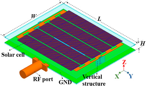
The proposed dual-band antenna integrated with solar cells is shown in Figure 1 with a dimension of 83 × 68 × 3.4 mm3. Relong and FR4 laminates are adopted for the top, bottom, and vertical substrates. The Relong substrate has a thickness of 0.762 mm with a relative dielectric constant of 2.55, and a loss tangent of 0.0009 while the FR4 substrate has a thickness of 0.6 mm with a relative dielectric constant of 4.4, and loss tangent of 0.02. An air gap of 2 mm separates the bottom and top substrates.
One type of solar cell with the size of 11.2 mm × 11.5 mm is chosen for the dual-function design. Its multi-layer structure is depicted in Figure 2, which is similar to that in [22]. As the size of a single solar cell is relatively small compared with the wavelength of its working frequency, six solar cells are in a serial connection with every two adjacent solar cells overlapped along the long edge. The antenna structure is in Figure 3 with detailed parameters in Table 1. It has the same polarization for two bands in the X-direction.
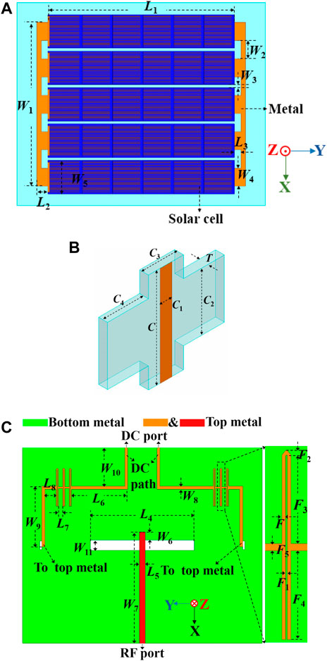
FIGURE 3. The structure of the solar cell antenna: (A) Top view, (B) Vertical structure, (C) Bottom view.
In Figure 3A, five rectangular patches made of solar cells are placed on the FR4 substrate. Each solar cell strip has a length of L1 and a width of W5. The anode and cathode of five solar cell strips are connected to the copper structures with the sizes of L2, L3, W1, W2, and W4. In Figure 3C, the ground plane is printed on the top of the Relong substrate while the feeding strip and the DC path are printed on the bottom. The aperture coupling method is adopted for the excitation with a coupling slot at the center of the ground plane. Electromagnetic coupling is also an effective way to prevent the DC energy from the RF port. To block the RF current to the DC port, microstrip bandstop filters are added at the DC path [30].
The DC transmission line includes the top copper structures, DC path with filters on the bottom substrate, and vertical strips printed on the vertical substrate to connect the bottom DC path and top metallic structure, as shown in Figures 1, 3B. The vertical substrate is also used to support the top structure.
Antenna Analysis
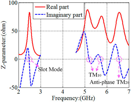
To clarify the working mechanism of the dual-band antenna, Z-parameters are depicted in Figure 4 and its working modes are investigated. It is observed from Figure 4 that there are one resonant frequency point at the lower band and three resonant frequency points at the higher band. The current and E-field distributions are plotted for the lower and upper bands to analyze these resonant modes.
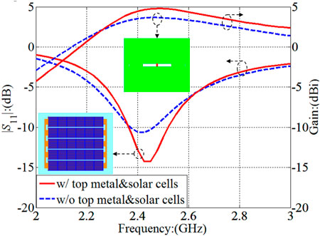
For the lower band, to analyze the influence of the top structure on the antenna performance, the S-parameter and gain with and without top structure are plotted in Figure 5. It is observed that the top structure has certain effects on the antenna performance at the lower band. The -10-dB bandwidth can be barely maintained at 2.4 GHz without top structure. After loading top structure, the impedance matching has been improved and the gain in the normal direction is 0.93 dB higher than that without top structure. The radiation patterns with and without top structure are plotted in Figure 6 at 2.4 GHz. It is noticed that the front-to-back ratio is about 0.5 dB higher after loading the top structure. So, it can be concluded that the resonant mode at 2.4 GHz is independent of the top structure. Furthermore, the effective current distribution of the ground plane is also plotted in Figure 7 and the antenna is with the slot mode at 2.4 GHz.
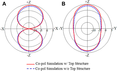
FIGURE 6. The influence of top metal and solar cells on the radiation patterns at 2.4 GHz: (A) E-plane, (B) H-plane.
For the higher band, the instantaneous E-field distribution is plotted in Figures 8A,B,C. Based on the E-field distribution, it is clear that TM10 modes are excited at 5.2 and 5.7 GHz, and the antiphase TM20 mode is stimulated at 6.5 GHz. The slot structure on the ground acts as the excitation for the microstrip antenna at the upper band. To sum up, the proposed antenna has different resonant modes for dual-band performance. It is with the slot mode at the lower band and the cavity mode (TM10 and antiphase TM20) at the higher band.
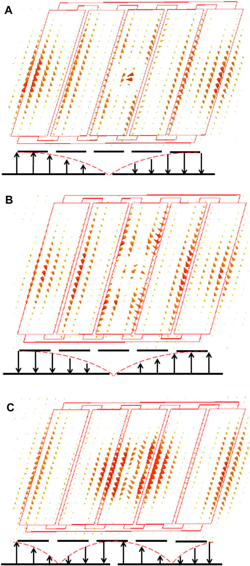
FIGURE 8. Instantaneous E-field distribution at higher band: (A) 2.4 GHz, (B) 5.2 GHz, (C) 5.7 GHz, (D) 6.5 GHz.
Experimental Verification
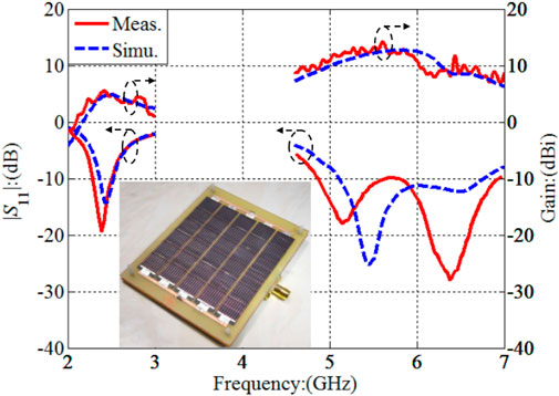
To verify the proposed dual-band design integrated with solar cells, a prototype is fabricated and thirty solar cells are assembled on the top structure, as shown in Figure 9. The S-parameter is measured by the Rohde and Schwarz ZVA24 network analyzer and the radiation performance is tested in an anechoic chamber. The software High-Frequency Structure Simulator (HFSS) is adopted for the numerical simulation.
The simulation and measurement results of the S-parameter and gain are plotted in Figure 9. The simulated −10-dB bandwidth is from 2.37 to 2.51 GHz at the lower band and from 5.1 to 6.7 GHz at the higher band. The measured −10-dB bandwidth is from 2.27 to 2.5 GHz at the lower band and from 4.8 to 6.9 GHz at the higher band. The target bands of 2.4, 5.2, and 5.8 GHz have been entirely covered.
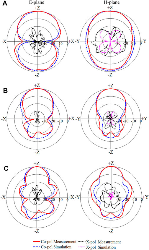
For the lower band, the measured gain is 5.25 dBi at 2.4 GHz, while the simulated gain is 4.45 dBi. For the higher band, the measured gains at 5.2 and 5.8 GHz are 12.2 and 12 dBi, respectively. The simulated gains at 5.2 and 5.8 GHz are 11 and 12.67 dBi, respectively. An average measured gain of 10.58 dBi is realized at the higher band. The radiation patterns are plotted in Figure 10. It is observed that an omnidirectional radiation pattern is achieved at 2.4 GHz in Figure 10A with the measured cross-polarization levels of less than −15 dB. Unidirectional radiation patterns are obtained at 5.2 and 5.8 GHz, as shown in Figures 10B,C. The measured cross-polarization levels are less than −21 dB with the measured back-lobe level better than −10 dB.
It is observed that certain differences exist between the simulation and measurement results, which is mainly due to the assembly error. In the fabrication procedure, the solar cells are overlapped and soldered together, the anode and cathode of each solar strip are soldered to the metallic structure. All these processes are conducted manually and the actual size is larger than the design, so the measured performance is shifted to the lower band slightly.
The proposed antenna integrated with solar cells is compared with some published solar cell antennas in Table 2. The solar cells are treated as a parasitic structure in [10, 12]. A slot antenna was reported in [10] with a measured gain of 6.62 dBi at 5.8 GHz. A low-profile multiband PIFA integrated with solar cells was presented in [12]. Measured gains of 4.7 and 5.5 dBi have been realized at 2.4 and 5.8 GHz, respectively. Using the solar cells as a radiation structure, a single-band low-profile antenna was investigated at 2.4 GHz with measured gain of 8.55 dBi at 2.4 GHz [26]. A slot antenna integrated with solar cells was discussed in [27]. Dualband performance is obtained at 2.4 and 5.2 GHz with the measured gains of 3.5 and 3.1 dBi. To enhance the bandwidth, a novel dual-band solar cell antenna is designed in this work. The aforementioned frequency bands of 2.4, 5.2 and 5.8 GHz have been fully covered with enhanced gains at both bands.
Optical Experiment
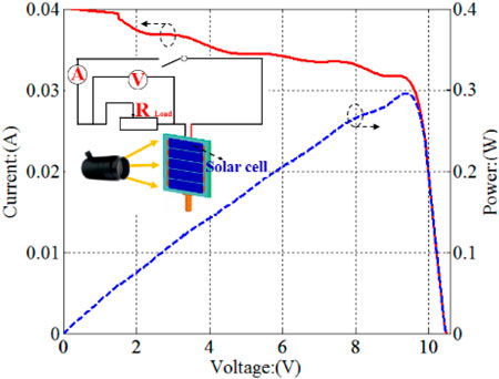
To test its ability of DC power generation, an optical experiment is conducted and the experimental setup is depicted in Figure 11. A light source with a light intensity of 1000 W/m2 is adopted to illuminate the solar cells, which can be treated as a voltage source with certain inner resistance. A variable resistor acts as the load, which is connected to the anode and cathode of the DC port of the solar cell antenna. Voltmeter and ammeter are employed to measure the voltage and current of the resistance load so that the output power can be calculated.
The results of the optical experiment are also plotted in Figure 11. The value of the variable resistor increases from zero, it is observed that the load voltage starts to rise and the current starts to decrease due to the increased resistance. The output power also begins to increase, it reaches the maximum point when the resistor is 299.5 Ω, then starts to decrease when the resistor continues to increase. The output power can peak when the load resistance is equal to the inner source resistance based on the circuit theory. So, the resistance of the equivalent source is obtained when the light intensity is 1000 W/m2.
Conclusion
A dual-band antenna integrated with solar cells is designed for the WLAN. The one-wavelength slot mode is excited for the lower band while the cavity modes of TM10 and antiphase TM20 are stimulated for the higher band. Relative bandwidths of 9.6 and 35.9% have been achieved for the lower and higher bands, respectively. The lower band has an omnidirectional radiation pattern, which is proper for receiving while the higher band has a unidirectional radiation pattern, which is suitable for transmitting. Furthermore, this solar cell antenna with the ability of DC power generation makes it preferable for the outdoor anonymous platform and green communication. With these favorable characteristics, this dual-band antenna integrated with solar cells should find extensive applications in the future.
Data Availability Statement
The original contributions presented in the study are included in the article/Supplementary Material, further inquiries can be directed to the corresponding author.
Author Contributions
WA provides the idea and fabrication, HW conducts the simulation and measurement, YL provides the optimization and instruction. WA and YL prepare the original manuscript.
Conflict of Interest
The authors declare that the research was conducted in the absence of any commercial or financial relationships that could be construed as a potential conflict of interest.
Publisher’s Note
All claims expressed in this article are solely those of the authors and do not necessarily represent those of their affiliated organizations, or those of the publisher, the editors and the reviewers. Any product that may be evaluated in this article, or claim that may be made by its manufacturer, is not guaranteed or endorsed by the publisher.
References
1. Lai HW, Wong H. Substrate Integrated Magneto-Electric Dipole Antenna for 5G Wi-Fi. IEEE Trans Antennas Propagat (2015) 63(2):870–4. doi:10.1109/tap.2014.2384015
2. Hu H-T, Chen F-C, Chu Q-X. A Compact Directional Slot Antenna and its Application in MIMO Array. IEEE Trans Antennas Propagat (2016) 64(12):5513–7. doi:10.1109/tap.2016.2621021
3. Sun W, Li Y, Zhang Z, Chen P-Y. Low-Profile and Wideband Microstrip Antenna Using Quasi-Periodic Aperture and Slot-To-CPW Transition. IEEE Trans Antennas Propagat (2019) 67(1):632–7. doi:10.1109/tap.2018.2874801
4. Sun W, Li Y, Zhang Z, Feng Z. Broadband and Low-Profile Microstrip Antenna Using Strip-Slot Hybrid Structure. Antennas Wirel Propag Lett (2017) 16:3118–21. doi:10.1109/lawp.2017.2763987
5. Sim C-Y -D, Chen C-C, Zhang XY, Lee Y-L, Chiang C-Y. Very Small-Size Uniplanar Printed Monopole Antenna for Dual-Band WLAN Laptop Computer Applications. IEEE Trans Antennas Propagat (2017) 65(6):2916–22. doi:10.1109/tap.2017.2695528
6. Sun XL, Liu L, Cheung SW, Yuk TI. Dual-band Antenna with Compact Radiator for 2.4/5.2/5.8 GHz WLAN Applications. IEEE Trans Antennas Propagat (2012) 60(12):5924–31. doi:10.1109/tap.2012.2211322
7. Sim C-Y -D, Chien H-Y, Lee C-H. Dual-/Triple-Band Asymmetric Dipole Antenna for WLAN Operation in Laptop Computer. IEEE Trans Antennas Propagat (2013) 61(7):3808–13. doi:10.1109/tap.2013.2257648
8. Lee C-T, Su S-W, Chen S-C, Fu C-S. Low-cost, Direct-Fed Slot Antenna Built in Metal Cover of Notebook Computer for 2.4-/5.2-/5.8-GHz WLAN Operation. IEEE Trans Antennas Propagat (2017) 65(5):2677–82. doi:10.1109/tap.2017.2679070
9. Sim D-U, Choi J-I. A Compact Wideband Modified Planar Inverted $F$ Antenna (PIFA) for 2.4/5-GHz WLAN Applications. Antennas Wirel Propag Lett (2006) 5:391–4. doi:10.1109/lawp.2006.881914
10. Zhang Z, Bai B, Li X, Liu Y, Sun C, Zhang Y. Integration of Circularly Polarized Microstrip Slot Array Antenna with Amorphous Silicon Solar Cells. Antennas Wirel Propag Lett (2020) 19(12):2320–3. doi:10.1109/lawp.2020.3031608
11. Vaccaro S, Pereira C, Mosig JR, de Maagt P. In-Flight experiment for Combined Planar Antennas and Solar Cells (SOLANT). IET Microw Antennas Propag (2009) 3(8):1279–87. doi:10.1049/iet-map.2008.0410
12. Yurduseven O, Smith D. A Solar Cell Stacked Multi-Slot Quad-Band PIFA for GSM, WLAN and WiMAX Networks. IEEE Microw Wireless Compon Lett (2013) 23(6):285–7. doi:10.1109/lmwc.2013.2258006
13. O’Conchubhair O, McEvoy P, Ammann MJ. Integration of Antenna Array with Multicrystalline Silicon Solar Cell. IEEE Antennas Wireless Propag Lett (2015) 14:1231–4. doi:10.1109/LAWP.2015.2399652
14. O’Conchubhair O, Narbudowicz A, McEvoy P, Ammann MJ. Circularly Polarised Solar Antenna for Airborne Communication Nodes. Electron Lett (2015) 51(9):667–9. doi:10.1049/el.2015.0201
15. Lemey S, Declercq F, Rogier H. Dual-band Substrate Integrated Waveguide Textile Antenna with Integrated Solar Harvester. IEEE Antennas Wireless Propag Lett (2016) 13:269–72. doi:10.1109/LAWP.2014.2303573
16. Virili M, Georgiadis A, Collado A, Mezzanotte P, Roselli L. EM Characterization of a Patch Antenna with Thermo Electric Generator and Solar Cell for Hybrid Energy Harvesting. In: Proceedings of the IEEE Radio and Wireless Symposium; 25 Jan 2015; San Diego, CA, USA. IEEE (2015). p. 44–6.
17. Virili M, Georgiadis A, Mira F, Collado A, Alimenti F, Mezzanotte P, Roselli L. EH Performance of an Hybrid Energy Harvester for Autonomous Nodes. In: Proc. IEEE Topical Conf. Wireless Sensors Sensor Netw; 24 Jan 2016; Austin, TX, USA. IEEE (2016). p. 71–4. doi:10.1109/wisnet.2016.7444325
18. Yurduseven O, Smith D, Pearsall N, Forbes I. A Transparent Solar Patch Antenna for 2.4/2.5 GHz WLAN-WiMAX Applications. In: Proceedings of the 2nd International Symposium On Environment Friendly Energies And Applications; 25 June 2012; Newcastle Upon Tyne, UK. IEEE (2012). p. 614–7.
19. Ta SX, Park I. A Circularly Polarized Antenna Integrated with a Solar Cell Metasurface for CubeSat. In: Proceedings of the Asia-Pacific Microwave Conference; 6 November 2018; Kyoto, Japan. IEEE (2018). p. 696–8.
20. An W, Xu S, Yang F, Gao J. A Ka-Band Reflectarray Antenna Integrated with Solar Cells. IEEE Trans Antennas Propagat (2014) 62(11):5539–46. doi:10.1109/tap.2014.2354424
21. An W, Xiong L, Xu S, Yang F, Fu H-P, Ma J-G. A Ka-Band High-Efficiency Transparent Reflectarray Antenna Integrated with Solar Cells. IEEE Access (2018) 6:60843–51. doi:10.1109/access.2018.2875359
22. An W, Hong L, Luo Y, Ma K, Ma J, Huang X. A Wideband Dual-Function Solar Cell Dipole Antenna for Both Energy Harvesting and Wireless Communications. IEEE Trans Antennas Propagat (2021) 69(1):544–9. doi:10.1109/tap.2020.3005250
23. Yurduseven O, Smith D, Pearsall N, Forbes I. A Triband Short-Circuited Suspended Solar Patch Antenna. Propagation and EM Theory. In: Proceedings of the International Symposium on Antennas; 22 Oct 2012; Xi'an, China. IEEE (2012). p. 294–7.
24. Yurduseven O, Smith D, Elsdon M. Cross-coax Fed Wideband Solar Patch Antenna. In: Proceedings of the Conference on Microwave Techniques; 17 April 2013; Pardubice, Czech Republic. IEEE (2013). p. 25–30.
25. Yurduseven O, Smith D, Pearsall N, Forbes I. Design of a Highly Efficient Wideband Suspended Solar Array Antenna. In: Proceedings of the IEEE International Symposium on Antennas and Propagation; 8 July 2012; Chicago, IL, USA. IEEE (2012). p. 1–2. doi:10.1109/aps.2012.6348555
26. Zhao Y, An W, Luo Y, Li S, Xiong L, Yu S. Low-Profile Antenna Integrated with Solar Cells for the 2.4 GHz Band. Antennas Wirel Propag Lett (2021) 20(4):443–7. doi:10.1109/lawp.2021.3051795
27. Shynu SV, Ons MJR, Ammann MJ, McCormack SJ, Norton B. Dual Band A-Si:H Solar-Slot Antenna for 2.4/5.2 GHz WLAN Applications. In: Proc. 3rd Eur. Conf. Antennas Propag.; 23 March 2009; Berlin, Germany. IEEE (2009). p. 408–10.
28. An W, Zhao W, Wang H, Luo Y, Wang J, Huang X. Dual-Function Slot Antenna Integrated with Solar Cells for the 1.575-GHz Band. IEICE Electron Express (2016) 17(21):1–6. doi:10.1587/elex.17.20200322
29. O’Conchubhair O, Yang K, McEvoy P, Ammann MJ. Amorphous Silicon Solar Vivaldi Antenna. IEEE Antennas Wireless Propag Lett (2020) 15:893–6. doi:10.1109/LAWP.2015.2479189
Keywords: microstrip antenna, slot antenna, dual-function device, solar cell, dual-band
Citation: An W, Wang H and Luo Y (2021) Dual-Band Antenna Integrated With Solar Cells for WLAN Applications. Front. Phys. 9:775214. doi: 10.3389/fphy.2021.775214
Received: 13 September 2021; Accepted: 23 September 2021;
Published: 08 October 2021.
Edited by:
Kai-Da Xu, Xi’an Jiaotong University, ChinaReviewed by:
Liuge Du, Shandong University, ChinaWang Kai Xu, Harbin Institute of Technology, Shenzhen, China
Copyright © 2021 An, Wang and Luo. This is an open-access article distributed under the terms of the Creative Commons Attribution License (CC BY). The use, distribution or reproduction in other forums is permitted, provided the original author(s) and the copyright owner(s) are credited and that the original publication in this journal is cited, in accordance with accepted academic practice. No use, distribution or reproduction is permitted which does not comply with these terms.
*Correspondence: Yu Luo, eWx1b0B0anUuZWR1LmNu
 Wenxing An
 Hui Wang
 Yu Luo