- 1School of Electronic Science and Engineering, Nanjing University of Posts and Telecommunications, Nanjing, China
- 2School of Information Engineering, Suqian College, Suqian, China
In this article, a band-notched dual-polarized crossed dipole antenna is proposed for 2.4/5 GHz WLAN applications. The proposed antenna works on the WLAN 2.4-GHz (2.4–2.48 GHz) and 5-GHz (5.15–5.85 GHz) bands for a VSWR <2 with two radiation zeros within 3.4–3.6 GHz. First, an ultra-wideband crossed dipole antenna with an operating frequency of 2.4–5.8 GHz is designed using the grounded coplanar waveguide (GCPW) feeding structure. Second, a miniaturized defected microstrip structure (DMS) is embedded in the GCPW feeding strip to form a stopband behavior with a radiation zero. Finally, combining with the design of a C-shaped split ring resonator (SRR) on the arms of the dipole antenna, a band notch (3.4–3.6 GHz) with two radiation zeros can be realized. These two radiation zeros can be adjusted independently to achieve a wide stopband performance. As a result, compared with the original ultra-wideband dipole antenna, the realized gains of the proposed antenna in the 3.4–3.6 GHz range are all suppressed from 8 dBi to less than −8 dBi. The proposed antenna can realize the stable unidirectional radiation pattern and a high gain of around 7 dBi in the lower band and 8.5 dBi in the higher band of WLAN. As a demonstration, the proposed antenna is fabricated and measured, and the measurement results are in good agreement with the simulation results.
Introduction
In the current wireless communication systems, decoupling [1] and suppressing interference from other narrow-band systems [2] are extremely important for applications in high-density environments. In the application of MIMO WLAN, dual-band (2.4–2.484 and 5.15–5.85 GHz) dual-polarized antenna elements with high isolation and high gain are used to obtain excellent communication performance [3]. In order to avoid the undesired signals from other narrow-band systems, including the 5G and WiMAX communication systems (3.4–3.6 GHz), it is an effective way to introduce a stopband behavior into a wideband antenna with other technical standards unchanged.
The monopole antenna can realize the ultra-wideband characteristic with a notch to cover the WLAN bands [4, 5]. Although these band-notched monopole antennas can achieve good performance, they are not suitable for the dual-polarized applications with a unidirectional radiation pattern. The microstrip filtering antenna can achieve a deep rejection by introducing a filtering structure inside the antenna without increasing the antenna volume [6, 7]. However, the microstrip antenna bandwidth is not wide enough to occupy the 2.4/5-GHz WLAN band. The broadband Vivaldi antenna [8] can achieve the stopband characteristic by integrating band-stop filters in the feeding line. Nevertheless, the profile of the Vivaldi antenna is high and the gain is low.
The crossed dipole antenna has been widely used in WLAN and base station applications because of the advantages of the broad operating band, double polarization, good radiation pattern stability, small dimension, and easy manufacturing [2, 3, 9, 10]. In work [9], C-shaped strips are designed beside the feed lines and a notched band of 2.27–2.53 GHz is achieved. By placing U-shaped strips along the feed lines and etching split-ring slots on the main radiators, the antennas in [11, 12] can obtain second-order notched bands. In contrast to work [12], work [10] can achieve first-order and second-order notched bands by etching two more split-ring slots on the main radiators. The Ref. [2] achieves a stop band of 2.9–3.1 GHz by placing a cross-dumbbell–shaped parasitic element above the radiator. However, all antennas in works [2, 9, 10] adopt an additional feeding structure under the crossed dipole antennas or parasitic element above the dipoles, which increase fabrication cost and installation difficulty.
In article [3], a C-shaped split-ring resonator (SRR) is introduced into a broadband-crossed dipole antenna to realize a notched band, and no additional filter circuit is required under the antenna. Compared with the broadband antenna without the SRR, the stopband minimum gain of the band-notched antenna is suppressed from 8 to −9 dBi. With only one substrate, the installation of antenna is easy and the fabrication cost is low. However, the notched band has only one radiation zero, so it does not suppress all frequencies in the stopband very well.
In this article, a band-notched crossed dipole antenna with two radiation zeros is proposed for the 2.4/5 GHz WLAN applications. First, the original ultra-wideband crossed dipole antenna is designed using the grounded coplanar waveguide (GCPW) feeding structure to cover the frequency of 2.4–5.8 GHz. Then, to achieve a radiation zero, the miniaturized M-shaped defected microstrip structure (DMS) [13] resonator is added to the GCPW feeding strip. The length of the DMS resonator is close to half-wavelength at resonant frequency. At last, the C-shaped SRR on the arms of the dipole antenna is introduced to obtain the second radiation zero. As a result, the realized gain of the proposed antenna within 3.4–3.6 GHz is all suppressed from 8 dBi to below -8 dBi, compared with the original ultra-wideband crossed dipole antenna. The proposed antenna, realizing the stable unidirectional radiation pattern and a high gain of around 8 dBi, can be a good candidate antenna for the 2.4/5 GHz WLAN applications.
Structure of Antenna
Figures 1A and B present the overall structure of the proposed band-notched antenna. The antenna consists of one substrate, two coaxial cables, and a metal reflector. The antenna is printed on the top layer and bottom layer of the substrate. The coaxial cables pass through the reflector, and the outer conductor is connected to the reflector and fed to the crossed dipole antenna. The Rogers-4350 substrate is utilized with the permittivity of εr = 3.66, length of Ls = 40 mm, and thickness of Hs = 0.787 mm. The square metal reflector is employed under the substrate with the distance of H = 19 mm to realize the unidirectional radiation pattern. Ansys HFSS software was used for simulation, and the simulation thickness Hm of metallic layers of the substrate was set as 0.035 mm. Because Hm would affect the performance of the stopband filter, it is necessary to consider Hm in the process of simulation and design of the proposed band-notched filter.
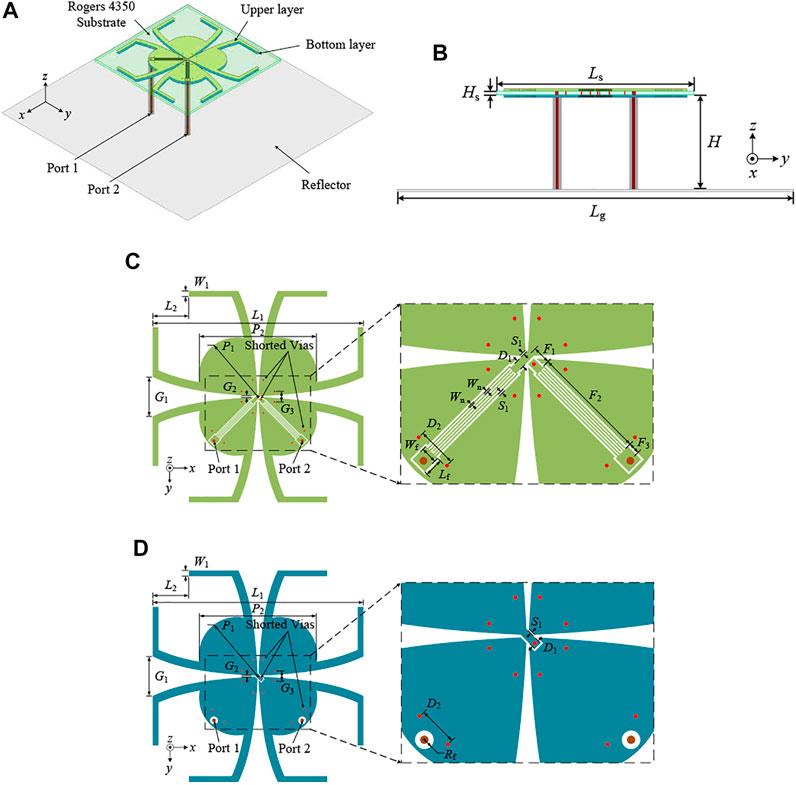
FIGURE 1. (A) Overall structure. (B) Side view. (Lg = 80, Ls = 40, H = 19, Hs = 0.787 mm). (C) Upper layer from top view. (D) Bottom layer from top view. (D1 = 0.6, D2 = 3, F1 = 1.38, F2 = 8.72, F3 = 0.9, G1 = 7, G2 = 0.2, G3 = 1.84, L1 = 37.2, L2 = 6.4, Lf = 1.4, P1 = 12, P2 = 21.6, Rf = 0.7, S1 = 0.15, W1 = 1, Wn = 0.1, Wf = 1.3 mm, and k = 0.125).
Figures 1C and D present the top layer and bottom layer from the top view of the proposed antenna, respectively. The top and bottom layers are connected to each other by nine shorted metalized vias, eight for connecting dipoles in the top and bottom layers and one for connecting the GCPW transmission line. The upper crossed dipoles have the same shape and size as the lower dipole. The internal part of the dipole arm is fan-shaped and the external part is the C-shaped SRR. The antenna arm edges between the crossed dipoles are designed in an exponential shape. The function of the exponential shape can be expressed as Y(x) = Cekx + B, where k is the constant coefficient of function. The GCPW structure can be designed inside these two metal layers. The outer conductor of the coaxial cable is connected to a dipole arm on the bottom layer of the substrate. The inner conductor is connected to one end of the GCPW strip by extending across the substrate. And the other end of the GCPW strip is connected to the other dipole arm. The partial line of the GCPW strip of port 2 is printed on the bottom layer of the substrate to avoid overlap, and the top and bottom parts of the GCPW strip are connected to each other using a shorted metallized via. There is an M-shaped DMS filter embedded in the GCPW feeding strip. The slot width and the metal width of DMS are both Wn.
Analysis of Antenna Design
GCPW Wideband Antenna
The broadband operating principle of the crossed dipole antenna is that the strong coupling between the two crossed dipoles introduces the second and third mode and greatly widens the bandwidth [2, 3, 10, 11]. Moreover, the arm spacing between the crossed dipoles, designed to vary exponentially, can improve the impedance matching [3, 14]. The exponential-shaped arms are adopted in the proposed dipole antenna to obtain a wide bandwidth in this article. As mentioned above, the function of the exponential shape can be expressed as Y(x) = Cekx + B. As the coefficient k gets smaller, the exponential line gets closer to a straight line.
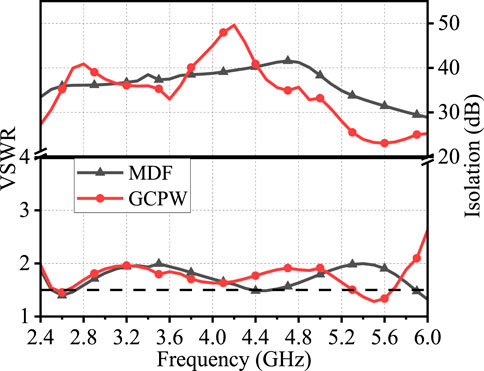
As a reference antenna, the broadband crossed dipole antenna using modified direct-feeding structure (MDF) is proposed in [3] and presented in Figure 2A. Then, the feeding structure of this wideband crossed dipole antenna is modified to the GCPW feeding structure, as shown in Figure 2B. Compared with the reference antenna, the feeding structure of the proposed antenna is changed into the GCPW structure with the inner arms printed with all metal instead of loop structure. Figure 3 exhibits the simulated results of the two antennas. Using the GCPW feeding structure, the proposed antenna can also achieve a wide bandwidth (2.4–5.85 GHz) and high isolation (more than 22 dB). Although the characteristics of the two antennas are similar, the proposed antenna can integrate filters on the GCPW feeding line. Therefore, the proposed broadband antenna is the basis of the integrating filter inside the antenna to realize filtering characteristics.
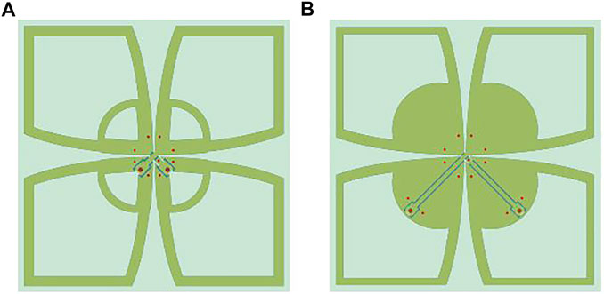
FIGURE 2. Two wideband antennas. (A) Wideband antenna using the MDF structure. (B) The proposed antenna using the GCPW structure.
GCPW Filter
To embed the band-notched filter into the proposed GCPW broadband antenna, the filter needs to be small in size. As shown in Figure 1, a miniaturized GCPW DMS filter is proposed in this article to realize a notched band of 3.4–3.6 GHz. The DMS is etched in the GCPW transmission line. The DMS resonator is nearly a half-wavelength at resonant frequency [13]. In order to explain its working principle more clearly, software HFSS is used to simulate the proposed bandstop filter, and software ADS is utilized to analyze its equivalent circuit.
Figures 4A–C show the U-, N-, and M-shaped DMS resonators, respectively. The slots of U-, N-, and M-shaped DMS resonators have one, two, and three bends, respectively. The resonant frequency versus F2 of these three filters are depicted in Figure 4D. It can be seen that the M-shaped DMS resonator can achieve a lower resonant frequency under same size. At the frequency of 3.5 GHz, only the M-shaped DMS resonator with the length of 8.6 mm can be embedded into the proposed wideband antenna in Figure 2B.

FIGURE 4. Three DMS resonators: (A) U-shaped, (B) Z-shaped, and (A) M-shaped. (D) Resonant frequencies of U-shaped, N-shaped, and M-shaped DMS resonators.
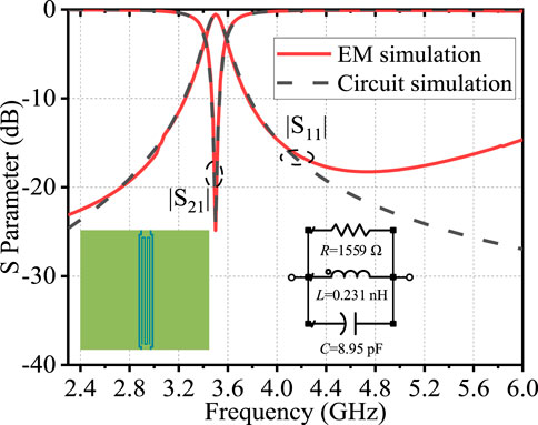
The equivalent circuit with a parallel RLC lumped element is reported to prove the concept of the transmission line of DMS [13–15]. The conventional stopband circuit parameters can be expressed in Eq. 1–3, where fc is the cut-off frequency (GHz), f0 is the resonant frequency (GHz), and Z0 is the characteristic impedance (Ω) of the GCPW transmission line. With F2 = 8.6 mm, the GCPW M-shaped DMS is simulated in software HFSS. The result of electromagnetic (EM) simulation shows that fc = 3.59 GHz, f0 = 3.5 GHz and |S11| = -0.54 dB = 0.94, and Z0 is set 50 Ω, as displayed in Figure 5. Then, according to Eq. 1–3, C = 8.95 nF, L = 0.231 nH, and R = 1,559 Ω can be calculated. The EM model and circuit model of the DMS resonator are shown in the lower left and right corner of Figure 5, respectively. The results of EM and circuit simulation are presented in Figure 5, and the simulation results have good agreement, which verifies the correctness of the equivalent circuit. Therefore, the equivalent circuit can assist in the rapid analysis of the performance of the antenna cascaded with filters.
The proposed DMS filter in Figure 4C and GCPW wideband antenna in Figure 2B are presented again in Figures 6A,B. When cascading the filter and wideband antenna, the equivalent circuit can be expressed in Figure 6C. Because two ports of the antenna have same impedance characteristics, only one port equivalent circuit is presented. As a reference, the DMS filter is embedded into the GCPW feeding line of the wideband antenna, as displayed in Figure 6D. The circuit simulation result of the equivalent circuit in Figure 6C and the EM simulation result of the band-notched antenna in Figure 6D are shown in Figure 7. The EM and circuit simulation results have good agreement. It can be seen that one notched band can be realized by the GCPW antenna with the DMS filter. Although the suppression performance of the GCPW band-notched antenna is good at 3.5 GHz, the notched bandwidth is not wide enough to cover 3.4–3.6 GHz.
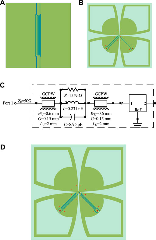
FIGURE 6. (A) Proposed DMS resonator, (B) wideband antenna, and (C) the equivalent circuit when cascading these two parts. (D) Band-notched antenna with the DMS resonator embedded into the GCPW feeding line of the wideband antenna.
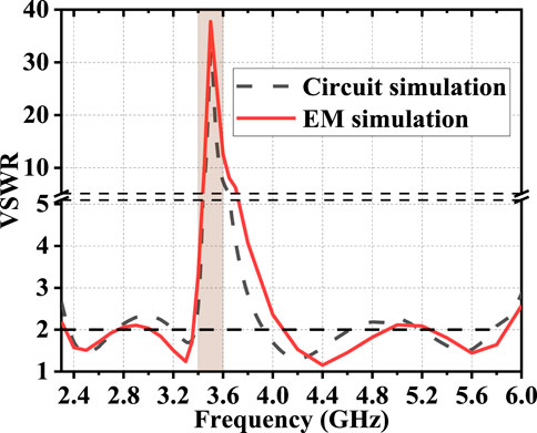
FIGURE 7. Circuit simulation result of the equivalent circuit, and the EM simulation result of the band-notched antenna.
Figures 8A and B show the proposed DMS filter in Figure 4C and the GCPW band-notched antenna with SRR [3], respectively. The cascading equivalent circuit can be expressed in Figure 8C. Here, only one port equivalent circuit is presented. Then, the DMS filter is embedded into the GCPW feeding line of the band-notched antenna, as presented in Figure 8D. The circuit simulation result of the equivalent circuit in Figure 8C and the EM simulation result of the band-notched antenna in Figure 8D are shown in Figure 9. The EM and circuit simulation results meet well. As a result, the proposed antenna in Figure 8D can realize a wider notched bandwidth, covering 3.4–3.6 GHz.
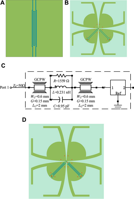
FIGURE 8. (A) Proposed DMS resonator, (B) one-order band-notched antenna, and (C) the equivalent circuit when cascading these two parts. (D) Proposed band-notched antenna with the DMS resonator embedded into the GCPW feeding line of the one-order band-notched antenna.
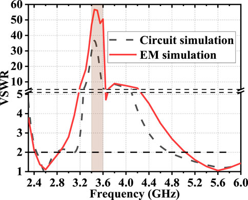
FIGURE 9. Circuit simulation result of the equivalent circuit, and EM simulation result of the proposed band-notched antenna.
Band-Notched Antenna
In order to better exhibit the evolution of the proposed GCPW band-notched antenna with two radiation zeros, the referenced wideband antenna, band-notched antenna with one radiation zero, and the proposed antenna are exhibited in Figures 10A–C, respectively. Compared with the broadband antenna, the band-notched antenna with one radiation zero antenna has the SRR on the dipole arms. Then, the proposed antenna utilizes the SRR and the GCPW DMS resonator at the same time without changing other designs.
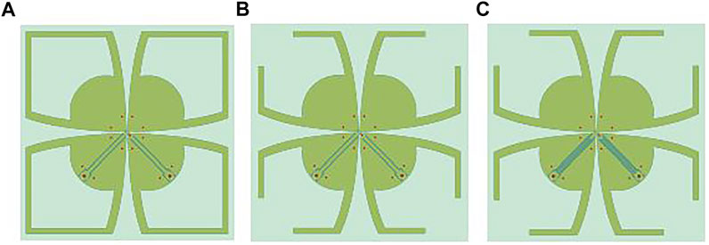
FIGURE 10. (A) Wideband antenna. (B) Band-notched antenna with one radiation zero. (C) Propose antenna with two radiation zeros.
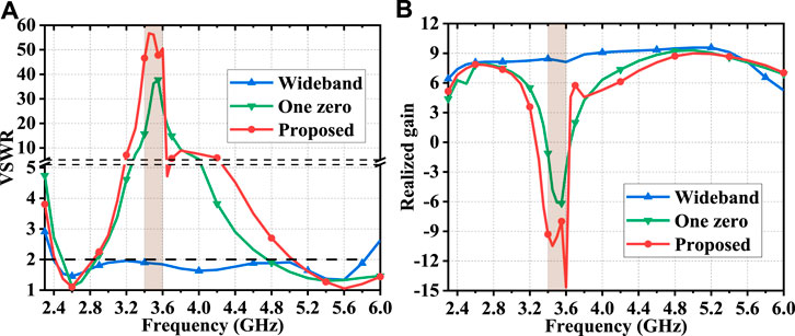
Figures 11A,B show the VSWR and realized gain of the three antennas. It can be seen that the broadband antenna covers 2.4–5.8 GHz for a VSWR <2 with a realized gain of 6–9 dBi. The band-notched reference antenna can achieve a notched band with a maximum VSWR of 38, and the realized gain within 3.4–3.6 GHz is from −6 to −1.5 dBi. The proposed antenna can obtain the VSWR bigger than 45 within 3.4–3.6 GHz, and the realized gain of the stopband is lower than −8 dBi with two radiation zeros. The antenna average gain is 7 dBi in the lower working band and 8 dBi in the higher working band. To conclude, the proposed antenna can achieve two working bands covering 2.4–2.5 GHz and 5.15–5.85 GHz for a VSWR <2 with high gain, and a notched band of 3.4–3.6 GHz with the gain suppression more than 16 dB.
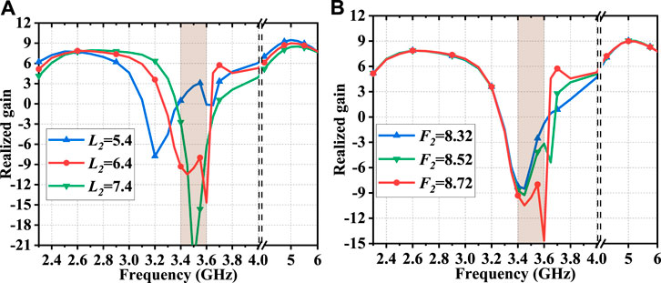
The impacts of parameters L2 and F2 on realized gain in the broadside direction are presented in Figures 12A,B, respectively. As can be seen from Figure 12A, with the increase of L2, the first radiation zero on the left moves towards the higher frequency and the second radiation zero remains nearly unchanged. Figure 12B shows that, when F2 increases, the second radiation zero moves to the lower frequency with the first radiation zero almost unchanged. Appropriate value of L2 and F2 should be chosen to ensure sufficient suppression performance and the notch bandwidth. Therefore, it can be concluded that two radiation zeros can be adjusted independently.
Experimental Validations
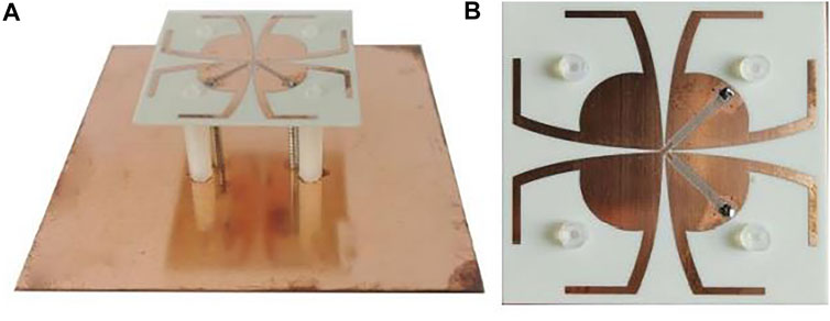
The measured results are achieved by an Agilent network analyzer (Agilent N5230A) and a far-field measurement system (NSI 2000). The proposed GCPW band-notched antenna is fabricated and displayed in Figure 13.
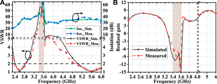
Figure 14A shows the simulation and measurement results of VSWR and isolation of the proposed antenna. The measured impedance bandwidth for a VSWR <2 is 2.4–2.85 GHz and 5–6 GHz, covering the 2.4/5-GHz WLAN band. The measured VSWR of the proposed antenna is larger than 25 within 3.4–3.6 GHz. The measured isolation is larger than 22 dB in the lower operating band and around 35 dB for the higher operating band.
Figure 14B displays the simulated and measured results of the realized gain in the broadside direction. The measured gain in the notched band of 3.4–3.6 GHz is lower than −6 dBi with two radiation zeros. The measured gain of the antenna for the 2.4-GHz WLAN band is around 7 dBi. The measured average gain is 8.5 dBi for the 5-GHz WLAN band. To conclude, the proposed antenna can achieve two working bands covering 2.4–2.5 GHz and 5.15–5.85 GHz for a VSWR <2 with high gain and a notched band of 3.4–3.6 GHz with the measured gain suppression more than 14 dB. The measured and simulated results meet well. The deviation between the simulation result and measurement result is mainly caused by the manufacturing, installation, and wideband measurement tolerance.
Figures 15A–C show the radiation patterns at the horizontal plane (YOZ plane) for 2.4, 5.2, and 5.8 GHz, respectively. It can be seen that the copolarization patterns are unidirectional and stable for these three frequencies. The cross-polarization in the broadside direction is less than 22 dB at 2.4 GHz and are less than 25 dB for the higher frequencies. The radiation patterns are a little distortion for the asymmetrical feeding structure. Nevertheless, the proposed band-notched antenna can realize the stable unidirectional radiation pattern, high gain, and a notched band with two radiation zeros.
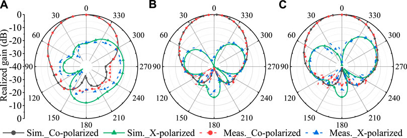
FIGURE 15. Simulated and measured radiation patterns at the horizontal plane for (A) 2.4 GHz, (B) 5.2 GHz, and (C) 5.8 GHz.
Table 1 shows the comparison among the proposed antenna and some reported band-notched crossed dipole antennas. The cited reference works are wideband crossed dipole antennas with band-notched characteristics and unidirectional radiation patterns. The antennas in [9–12] can achieve notched bands by using the U-shaped strips along the feed lines or etching split-ring slots on the main radiators. However, because these works all have the working bandwidth of less than 55% (1.7–3 GHz) for a VSWR <1.5, they are not good candidates for the WLAN applications with the bandwidth of 83% (2.4–5.8 GHz) for a VSWR >2. In work given in reference [2], additional feeding structure is utilized to increase the bandwidth, and a parasitic element is added above the dipoles to introduce a notched band. The bandwidth for a VSWR <1.5 covers 1.7–3.6 GHz, and the antenna is possible to be modified for the WLAN applications with a VSWR <2. However, the antenna uses an additional balun structure and parasitic element, which increase the manufacturing cost and installation difficulty. Besides, the gain suppression in the notched band is only about 4 dB. With only one substrate, the band-notched antenna in [3] is suitable for WLAN applications with high gain and easy for installation. However, there is only one radiation zero in the notched band, therefore, not all frequencies in the stopband can be well suppressed. To conclude, the proposed antenna can achieve an ultra-wide bandwidth (2.4–5.8 GHz) with a notched band (3.4–3.6 GHz) for WLAN applications with high gain. The gain in the stopband is less than -8 dBi. Moreover, with only one substrate, the installation of the antenna is easy and the fabrication cost is low.
Conclusion
In this article, an ultra-wideband crossed dipole antenna with two radiation zeros is proposed for 2.4/5 GHz WLAN applications. The proposed antenna has two operating bands (2.4- and 5-GHz WLAN bands) and a notched band (3.4–3.6 GHz). With only one substrate, the band notch is achieved with two radiation zeros by utilizing an M-shaped defected microstrip structure (DMS) filter embedded in the grounded coplanar waveguide (GCPW) feeding strip. The proposed antenna can realize a high gain of around 7 dBi in the lower operating band and 8.5 dBi in the higher operating band. The gain suppression in the notched band is more than 16 dB. Because of the band-notched characteristics and stable unidirectional radiation patterns with high gain, the proposed band-notched antenna can be an excellent candidate for wireless communication systems, such as the MIMO WLAN applications.
Data Availability Statement
The original contributions presented in the study are included in the article/Supplementary Material; further inquiries can be directed to the corresponding author.
Author Contributions
ML designed the structure, fabricated the sample, and wrote the article with contribution from FX. All authors participated in the discussion of the results.
Funding
This work was supported by the National Natural Science Foundation of China under Grant No. 61871228.
Conflict of Interest
The authors declare that the research was conducted in the absence of any commercial or financial relationships that could be construed as a potential conflict of interest.
Publisher’s Note
All claims expressed in this article are solely those of the authors and do not necessarily represent those of their affiliated organizations or those of the publisher, the editors, and the reviewers. Any product that may be evaluated in this article, or claim that may be made by its manufacturer, is not guaranteed or endorsed by the publisher.
Supplementary Material
The Supplementary Material for this article can be found online at: https://www.frontiersin.org/articles/10.3389/fphy.2021.769949/full#supplementary-material
References
1. Xu K-D, Luyen H, Behdad N. A Decoupling and Matching Network Design for Single- and Dual-Band Two-Element Antenna Arrays. IEEE Trans Microwave Theor Techn. (2020) 68:3986–99. doi:10.1109/TMTT.2020.2989120
2. Fu S, Cao Z, Quan X, Xu C. A Broadband Dual-Polarized Notched-Band Antenna for 2/3/4/5G Base Station. Antennas Wirel Propag Lett (2020) 19:69–73. doi:10.1109/LAWP.2019.2953294
3. Zhang Y, Zhang Y, Li D, Liu K, Fan Y. Dual-Polarized Band-Notched Antenna without Extra Circuit for 2.4/5 GHz WLAN Applications. IEEE Access (2019) 7:84890–6. doi:10.1109/ACCESS.2019.2924494
4. Xu KD, Zhang YH, Spiegel RJ, Fan Y, Joines WT, Liu QH. Design of a Stub-Loaded Ring-Resonator Slot for Antenna Applications. IEEE Trans Microw Theor Tech (2015) 63:2. doi:10.1109/ACCESS.2019.2924494
5. Guo Y, Tang X, Xu KD, Ai J. Dual High-Selectivity Band-Notched UWB Monopole Antenna Using Simple Dual-Mode Resonator and High-Impedance Lines. Int J Microw Wireless Technol (2016) 9:923–9. doi:10.1017/S1759078716000775
6. Mao C-X, Gao S, Wang Y, Luo Q, Chu Q-X. A Shared-Aperture Dual-Band Dual-Polarized Filtering-Antenna-Array with Improved Frequency Response. IEEE Trans Antennas Propagat (2017) 65:1836–44. doi:10.1109/TAP.2017.2670325
7. Mao C-X, Gao S, Wang Y, Liu Y, Yang X-X, Cheng Z-Q, et al. Integrated Dual-Band Filtering/Duplexing Antennas. IEEE Access (2018) 6:8403–11. doi:10.1109/ACCESS.2018.2805224
8. Feng H, Zhang F, Zhang H. A Dual Polarized Vivaldi Antenna with the Notched Band by Feed Line Filter on Conductive Plane. In: Proceedings of the 2018 International Conference on Microwave and Millimeter Wave Technology (ICMMT); 2018 May; Chengdu, China (2018). doi:10.1109/ICMMT.2018.8563798
9. Huang H, Liu Y, Gong S. A Broadband Dual-Polarized Base Station Antenna with Anti-Interference Capability. Antennas Wirel Propag Lett (2017) 16:613–6. doi:10.1109/LAWP.2016.2594095
10. Chen Y-L, Chu Q-X. A Compact Dual Band-Notched and Dual-Polarization Antenna for Base Station. In: Proceedings of the 2019 International Conference on Microwave and Millimeter Wave Technology (ICMMT); 2019 May; Guangzhou, China (2019). doi:10.1109/ICMMT45702.2019.8992327
11. Chen Y-L, Chu Q-X. A Novel Filter Antenna for Base Station. In: Proceedings of the 2019 IEEE-APS Topical Conference on Antennas and Propagation in Wireless Communications (APWC); 2019 September; Granada, Spain (2019). doi:10.1109/APWC.2019.8870465
12. Li Y-N, Chu Q-X. A Broadband Dual-Polarized Base Station Antenna with Second-Order Band-Notched Characteristics. In: Proceedings of the 2019 IEEE MTT-S International Wireless Symposium (IWS); 2019 May; Guangzhou, China (2019). doi:10.1109/IEEE-IWS.2019.8804078
13. Sam WY, Zakaria Z, Mutalib MA, Fadhli MFM, Othman AR, Isa AAM. A Compact DMS Triple-Band Bandstop Filter with U-Slots for Communication Systems. In: Proceedings of the 2014 2nd International Conference on Electronic Design (ICED); 2014 August; Penang, Malaysia (2014). doi:10.1109/ICED.2014.7015835
14. Zhang Y, Li D, Zhang Y, Fan Y. Compact Wideband Dual-Polarized Antenna with High Isolation Using Modified Direct Feeding Structure for Indoor Beamforming Array Applications. IEEE Access (2018) 6:66396–402. doi:10.1109/ACCESS.2018.2878760
15. Zakaria Z, Mutalib MA, Ismail A, Isa MSM, Ismail MM, Latiff AA, et al. Compact Structure of Band-Pass Filter Integrated with Defected Microstrip Structure (DMS) for Wideband Applications. In: Proceedings of the The 8th European Conference on Antennas and Propagation (EuCAP 2014); 2014 April; Hague, Netherlands (2014). doi:10.1109/EuCAP.2014.6902236
Keywords: band-notched, DMS resonator, crossed dipole antenna, dual-polarized, two radiation zeros
Citation: Li M and Xu F (2021) A Band-Notched Antenna With Two Radiation Zeros Using Grounded Coplanar Waveguide Filter for 2.4/5 GHz WLAN Applications. Front. Phys. 9:769949. doi: 10.3389/fphy.2021.769949
Received: 02 September 2021; Accepted: 29 September 2021;
Published: 05 November 2021.
Edited by:
Gang Zhang, Nanjing Normal University, ChinaReviewed by:
Xuedao Wang, Jinling Institute of Technology, ChinaQingbo Li, Huaiyin Normal University, China
Copyright © 2021 Li and Xu. This is an open-access article distributed under the terms of the Creative Commons Attribution License (CC BY). The use, distribution or reproduction in other forums is permitted, provided the original author(s) and the copyright owner(s) are credited and that the original publication in this journal is cited, in accordance with accepted academic practice. No use, distribution or reproduction is permitted which does not comply with these terms.
*Correspondence: Feng Xu, ZmVuZy54dUBuanVwdC5lZHUuY24=
 Min Li
 Feng Xu1*