- 1Advanced Materials and Liquid Crystal Institute, Kent State University, Kent, OH, United States
- 2Department of Physics, Kent State University, Kent, OH, United States
- 3Materials Science Graduate Program, Kent State University, Kent, OH, United States
One objective of active matter science is to unveil principles by which chaotic microscale dynamics could be transformed into useful work. A nematic liquid crystal environment offers a number of possibilities, one of which is a directional motion of an active droplet filled with an aqueous dispersion of swimming bacteria. In this work, using the responsiveness of the nematic to the electric field and light, we demonstrate how to control the direction and speed of active droplets. The dielectric response of nematic to the electric field causes two effects: 1) reorientation of the overall director, and 2) changing the symmetry of the director configuration around the droplet. The first effect redirects the propulsion direction while the second one changes the speed. A laser beam pointed to the vicinity of the droplet can trigger the desired director symmetry around the droplet, by switching between dipolar and quadrupolar configurations, thus affecting the motility and polarity of propulsion. The dynamic tuning of the direction and speed of active droplets represents a step forward in the development of controllable microswimmers.
Introduction
Active colloids are self-propulsive units capable of transforming stored or ambient free energy into systematic movement [1–4]. In an isotropic environment, active colloids of both living and inanimate types move along random directions unless their trajectories are biased by gradients of chemicals, temperature, or other cues [5–7]. Liquid crystals, used as a medium for active colloids, offer a much higher control level over the microscale dynamics thanks to their long-range orientational order [4, 8, 9]. In particular, by designing patterns of the nematic director
Recent studies show that a nematic liquid crystal not only directs a microscale motion but could also enable it, as demonstrated by nonlinear electrokinetics [8, 11] and by steady directional propulsion of active droplets dispersed in a thermotropic nematic [18]. In the latter case, a spherical water droplet containing randomly swimming bacteria shows directional motility along the overall director [18]. The motility results from rectification of the chaotic flows inside the droplet by the orientationally ordered exterior. It relies on the symmetry of director distortions set by the perpendicular anchoring of the director at the surface of the droplet. A director field of dipolar symmetry, with a point defect-hedgehog on one side, makes the droplets motile, while a quadrupolar director configuration with an equatorial disclination ring does not [18]. The dipolar symmetry is the ground state of the system in the absence of confinement and external fields [19] but the quadrupolar symmetry becomes prevalent when the sample is shallow [20] or when a strong electric or magnetic field is applied [21–24].
In this work, using the responsiveness of a thermotropic nematic to the external electromagnetic fields, we demonstrate full control over the direction and speed of active droplets by two methods: 1) applying an alternating current (ac) electric field, and 2) pointing a laser beam at the nematic near the droplet. The electric field applied in the plane of the cell using patterned electrodes changes the propulsion direction by realigning the nematic director and controls the speed by transforming the dipolar director structure into the quadrupolar one. An out-of-plane electric field applied across the cell realigns the director perpendicularly to the substrates and thus reduces the in-plane asymmetry and the droplet’s speed. The laser beam locally melts the nematic and switches between dipolar and quadrupolar configurations. The laser beam can also reverse the propulsion direction by creating a hedgehog defect on the side that is intended to lead.
Materials and Methods
Active Droplets
We use rod-shaped swimming bacteria Bacillus subtilis (strain 1085) of a body length 5–7 μm and a diameter ∼0.7 μm. The bacteria are initially grown on Lysogeny broth (Miller composition from Teknova, Inc.) agar plates at 35°C for 12–24 h; then a colony is transferred to a Terrific Broth (TB) (Sigma Aldrich) liquid medium and grown in a shaking incubator at a temperature 35°C for 7–9 h. The concentration of bacteria during the growth stage is monitored by measuring the optical density. At the end of the exponential growth, the bacterial concentration is about
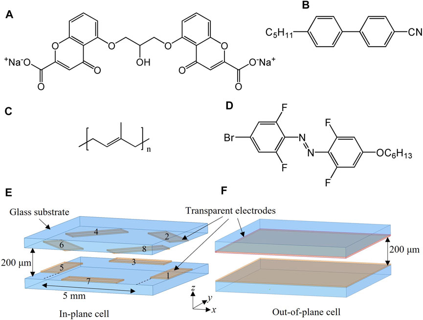
FIGURE 1. Chemical structure of (A) DSCG, (B) 5CB, (C) polyisoprene, (D) azodye BrOTFAzoO6. (E) Geometry of the cell with patterned segmented electrodes. Four electrodes are located on each substrate. The in-plane electric field is applied within the electrodes in the same plate. The scheme is not to scale. (F) Geometry of the cell with two transparent electrodes to apply an electric field across the cell.
Inactive Nematic Environment
A thermotropic nematic pentylcyanobiphenyl (5CB) (Merck) is used as the continuous medium, Figure 1B. The dielectric anisotropy of 5CB is positive,
Cell Preparation
The emulsion of active droplets in 5CB is filled into cells of a thickness
Electrode Design and Electric Field Application
Two different geometries of the electrodes are designed to apply the electric field. 1) A segmented set of eight electrodes is used to apply an in-plane electric field along different directions, Figure 1E. We call this an “in-plane cell”. Four electrodes are located at each bounding plate and the separation distance between the opposite electrodes is
Laser Excitation
An Nd: YVO4 laser (Coherent Verdi-V6) with the wavelength of 532 nm is used to change the director configuration near the active droplets. 5CB is doped with
The motion of active droplets is observed under an inverted Nikon TE2000 optical microscope equipped with a videocamera Emergent HS-20000C; the trajectories are tracked using the ImageJ software [30].
Results and Discussion
The surfactant lecithin imposes perpendicular alignment of the nematic 5CB director at the surface of active droplets. The 5CB director around the droplets adopts either a dipolar structure with a point defect called a hyperbolic hedgehog (HH) [19], Figure 2A, or an equatorial disclination ring, referred to as a Saturn ring (SR) [31], Figure 2B. The director
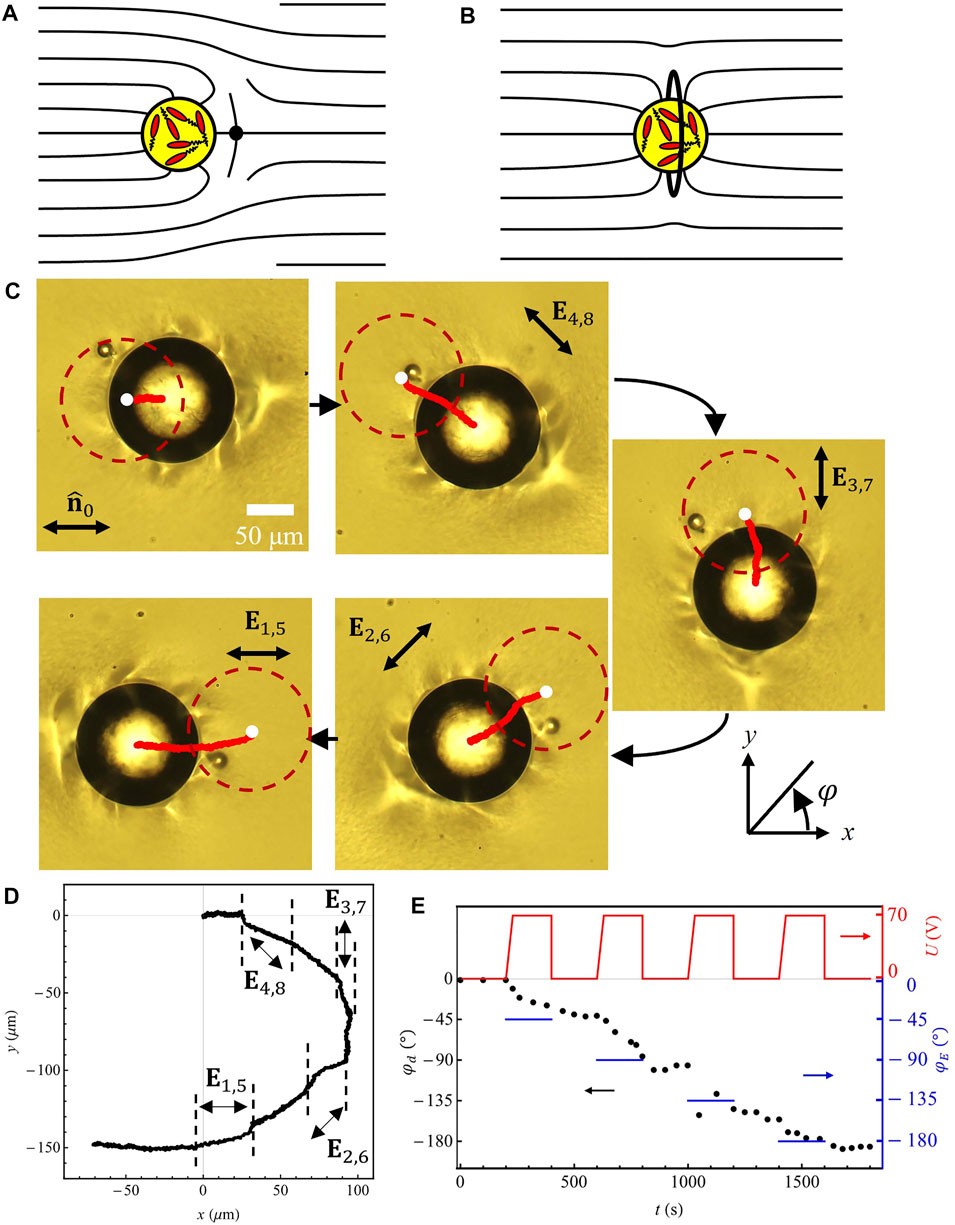
FIGURE 2. Electric field control of propulsion direction of active droplets in the nematic 5CB. Director configuration around a sphere with perpendicular surface anchoring that produces (A) a point-defect hyperbolic hedgehog or (B) a Saturn ring. (C) The sequence of images shows the trajectory of the active droplet.
Redirecting the active droplets by an in-plane electric field
An in-plane electric field is applied to 5CB through the segmented electrodes illustrated in Figure 1E. The field realigns the overall director from the initial orientation
Because of the sandwich geometry of the cell with two electrodes supplying an in-plane electric field, the actual value of the field is smaller than the simple relationship
The active droplet redirection is defined by the field-induced director realignment. Figure 3 compares the time evolution of the angle
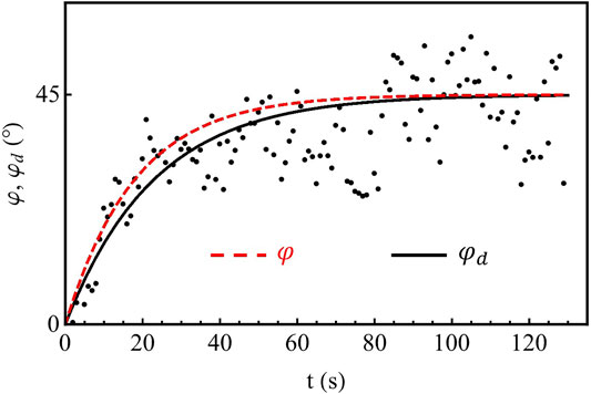
FIGURE 3. The angle
Since the azimuthal surface anchoring is negligibly small, the time evolution of
where
The active droplet trajectory angle
Speed control by an in-plane electric field
The in-plane electric field could also control the speed of active droplets by changing the degree of director asymmetry, mainly through the transformation of HH into SR, Figures 4A–C. We quantify the asymmetry degree by the ratio
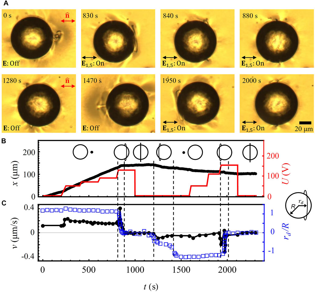
FIGURE 4. (A) Transformation of a HH into a disclination ring by an electric field.
Speed control by an out-of-plane electric field
The speed of active droplets could also be controlled by the electric field applied across the cell, using transparent electrodes at the bounding plates, Figure 1F. The 5CB director tends to align parallel to the electric field, i.e., normally to the cell’s substrates. At small fields, the director far away from the drop remains in the xy plane because of the polar anchoring at the bounding substrates, Figures 5A,B. The director realignment around the droplet reduces the asymmetry of HH structure projected onto the xy plane and thus decreases the speed, Figures 5A–C. At higher voltages,
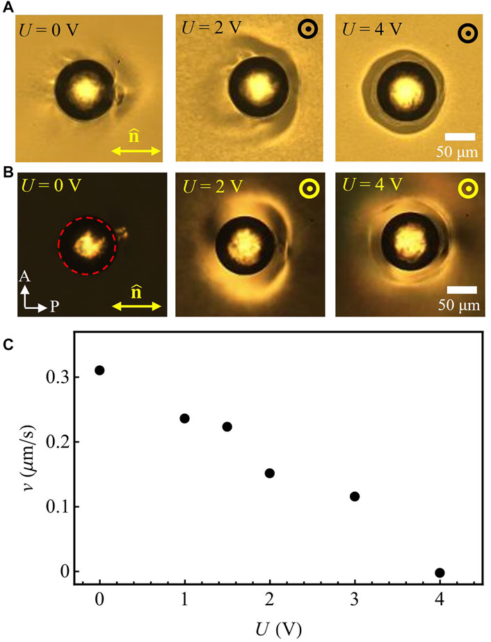
FIGURE 5. Polarizing microscopy observations in (A) bright field, and (B) with crossed polarizers of active droplets at different applied voltages. The field direction is normal to the cell.
Controlling speed and polarity of motion by a focused laser beam
A laser beam can tune the motility and polarity of motion of active droplets. The speed relates to the degree of asymmetry of the director around the droplet. The polarity of motion depends on the location of the HH since the HH leads the droplet. One can establish the desired director configuration, either SR or HH, by locally melting 5CB near the sphere by a laser beam, Figure 6. The laser beam focused on one side of an SR droplet (left side in Figure 6A,
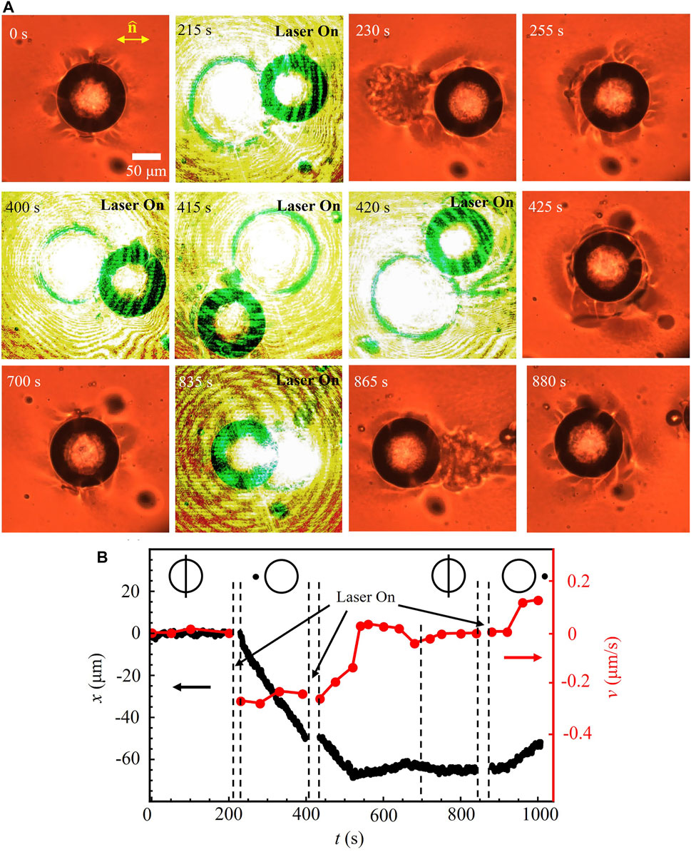
FIGURE 6. Control of speed and polarity of droplet propulsion by light. (A) A stationary active droplet with an SR director configuration. A laser beam is pointed to the left side of the droplet and forms an HH on that side. Then, the laser is moved around the droplet at a distance of about
Conclusion
We demonstrated an approach to dynamically control the speed and direction of propulsion of active droplets using an electric field and light. The director field of the nematic environment in which the active droplet is placed realigns parallel to the field and provides a guiding direction for the active droplet. We redirect the droplet by changing the in-plane field direction through a designed set of segmented electrodes. The electric field applied parallel to the overall director controls the speed of the active droplet. In response to the field, the dipolar HH structure transforms into a quadrupolar SR structure with an equatorial disclination ring, which reduces the speed to zero. When the field is switched off, the nematic director around the droplet reconstructs the HH and the droplet resumes a steady unidirectional motion. An out-of-plane electric field also reduces the speed of droplet by realigning the nematic director perpendicularly to the bounding plates and thus reducing the in-plane asymmetry of the HH structure. Using a laser beam, we reversibly transform the immobile SR active droplets into steady propelling HH droplets. We also can change the polarity of motion by first transforming an HH into an SR by a laser or by an electric field and then creating a new HH on the opposite side by a laser beam.
The typical redirection times are on the order of 102 s. These could certainly be shortened, by raising the tunning electric field and using a nematic of a lower viscosity and higher susceptibility to the field.
The observed field-induced HH-SR transformations suggest that the diameter
The advantage of an electric field and laser beams as the means to control the motion of active droplets is their dynamic nature. The previous methods such as patterning of the nematic director were built on a predesigned path approach, where the path of the active colloids was not adjustable once determined [11, 18]. The techniques proposed in our work allow one to adjust the propulsion direction and speed of active droplets in real-time and thus represent a step forward in the design of active and intelligent living matter.
Data Availability Statement
The original contributions presented in the study are included in the article/Supplementary Material, further inquiries can be directed to the corresponding author.
Author Contributions
MR performed the experiments with the help of HB. HW synthesized the azo-dye. MR performed the numerical simulation. MR and ODL analyzed the data and wrote the paper with the input from all co-authors. ODL supervised the project.
Funding
The work is supported by the NSF grant DMR-1905053.
Conflict of Interest
The authors declare that the research was conducted in the absence of any commercial or financial relationships that could be construed as a potential conflict of interest.
Publisher’s Note
All claims expressed in this article are solely those of the authors and do not necessarily represent those of their affiliated organizations, or those of the publisher, the editors and the reviewers. Any product that may be evaluated in this article, or claim that may be made by its manufacturer, is not guaranteed or endorsed by the publisher.
Acknowledgments
We thank Sergij V. Shiyanovskii for fruitful discussions and Jie Xiang for help with the simulations.
Supplementary Material
The Supplementary Material for this article can be found online at: https://www.frontiersin.org/articles/10.3389/fphy.2021.752994/full#supplementary-material
References
1. Marchetti MC, Joanny JF, Ramaswamy S, Liverpool TB, Prost J, Rao M, et al. Hydrodynamics of Soft Active Matter. Rev Mod Phys (2013) 85:1143–89. doi:10.1103/RevModPhys.85.1143
2. Ramaswamy S. The Mechanics and Statistics of Active Matter. Annu Rev Condens Matter Phys (2010) 1:323–45. doi:10.1146/annurev-conmatphys-070909-104101
4. Lavrentovich OD. Active Colloids in Liquid Crystals. Curr Opin Colloid Interf Sci (2016) 21:97–109. doi:10.1016/j.cocis.2015.11.008
5. Maass CC, Krüger C, Herminghaus S, Bahr C. Swimming Droplets. Annu Rev Condens Matter Phys (2016) 7:171–93. doi:10.1146/annurev-conmatphys-031115-011517
6. Sanchez T, Chen DTN, Decamp SJ, Heymann M, Dogic Z. Spontaneous Motion in Hierarchically Assembled Active Matter. Nature (2012) 491:431–4. doi:10.1038/nature11591
7. Gangwal S, Cayre OJ, Bazant MZ, Velev OD. Induced-charge Electrophoresis of Metallodielectric Particles. Phys Rev Lett (2008) 100:058302. doi:10.1103/PhysRevLett.100.058302
8. Lavrentovich OD. Design of Nematic Liquid Crystals to Control Microscale Dynamics. Liquid Crystals Rev (2020) 8:59–129. doi:10.1080/21680396.2021.1919576
9. Zhang R, Mozaffari A, de Pablo JJ. Autonomous Materials Systems from Active Liquid Crystals. Nat Rev Mater (2021) 6:437–53. doi:10.1038/s41578-020-00272-x
11. Lavrentovich OD, Lazo I, Pishnyak OP. Nonlinear Electrophoresis of Dielectric and Metal Spheres in a Nematic Liquid crystal. Nature (2010) 467:947–50. doi:10.1038/nature09427
12. Mushenheim PC, Trivedi RR, Roy SS, Arnold MS, Weibel DB, Abbott NL. Effects of Confinement, Surface-Induced Orientations and Strain on Dynamical Behaviors of Bacteria in Thin Liquid Crystalline Films. Soft Matter (2015) 11:6821–31. doi:10.1039/C5SM01489A
13. Peng C, Guo Y, Conklin C, Viñals J, Shiyanovskii SV, Wei Q-H, et al. Liquid Crystals with Patterned Molecular Orientation as an Electrolytic Active Medium. Phys Rev E (2015) 92:052502. doi:10.1103/PhysRevE.92.052502
14. Peng C, Turiv T, Guo Y, Wei Q-H, Lavrentovich OD. Command of Active Matter by Topological Defects and Patterns. Science (2016) 354:882–5. doi:10.1126/science.aah6936
15. Turiv T, Koizumi R, Thijssen K, Genkin MM, Yu H, Peng C, et al. Polar Jets of Swimming Bacteria Condensed by a Patterned Liquid crystal. Nat Phys (2020) 16:481–7. doi:10.1038/s41567-020-0793-0
16. Turiv T, Krieger J, Babakhanova G, Yu H, Shiyanovskii SV, Wei Q-H, et al. Topology Control of Human Fibroblast Cells Monolayer by Liquid crystal Elastomer. Sci Adv (2020) 6:eaaz6485. doi:10.1126/sciadv.aaz6485
17. Koizumi R, Turiv T, Genkin MM, Lastowski RJ, Yu H, Chaganava I, et al. Control of Microswimmers by Spiral Nematic Vortices: Transition from Individual to Collective Motion and Contraction, Expansion, and Stable Circulation of Bacterial Swirls. Phys Rev Res (2020) 2:033060. doi:10.1103/PhysRevResearch.2.033060
18. Rajabi M, Baza H, Turiv T, Lavrentovich OD. Directional Self-Locomotion of Active Droplets Enabled by Nematic Environment. Nat Phys (2021) 17:260–6. doi:10.1038/s41567-020-01055-5
19. Poulin P, Stark H, Lubensky TC, Weitz DA. Novel Colloidal Interactions in Anisotropic Fluids. Science (1997) 275:1770–3. doi:10.1126/science.275.5307.1770
20. Gu Y, Abbott NL. Observation of Saturn-Ring Defects Around Solid Microspheres in Nematic Liquid Crystals. Phys Rev Lett (2000) 85:4719–22. doi:10.1103/PhysRevLett.85.4719
21. Loudet JC, Poulin P. Application of an Electric Field to Colloidal Particles Suspended in a Liquid-crystal Solvent. Phys Rev Lett (2001) 87:165503. doi:10.1103/PhysRevLett.87.165503
22. Stark H. Saturn-ring Defects Around Microspheres Suspended in Nematic Liquid Crystals: An Analogy between Confined Geometries and Magnetic fields. Phys Rev E (2002) 66:032701. doi:10.1103/PhysRevE.66.032701
23. Fukuda J-i., Stark H, Yoneya M, Yokoyama H. Dynamics of a Nematic Liquid crystal Around a Spherical Particle. J Phys Condens Matter (2004) 16:S1957–S1968. doi:10.1088/0953-8984/16/19/008
24. Fukuda J, Yokoyama H. Stability of the Director Profile of a Nematic Liquid crystal Around a Spherical Particle under an External Field. Eur Phys J E (2006) 21:341–7. doi:10.1140/epje/i2006-10072-6
25. Gu M, Yin Y, Shiyanovskii SV, Lavrentovich OD. Effects of Dielectric Relaxation on the Director Dynamics of Uniaxial Nematic Liquid Crystals. Phys Rev E (2007) 76:061702. doi:10.1103/PhysRevE.76.061702
26. Ramdane OO, Auroy P, Forget S, Raspaud E, Martinot-Lagarde P, Dozov I. Memory-Free Conic Anchoring of Liquid Crystals on a Solid Substrate. Phys Rev Lett (2000) 84:3871–4. doi:10.1103/PhysRevLett.84.3871
27. Smalyukh II, Lavrentovich OD. Anchoring-Mediated Interaction of Edge Dislocations with Bounding Surfaces in Confined Cholesteric Liquid Crystals. Phys Rev Lett (2003) 90:085503. doi:10.1103/PhysRevLett.90.085503
28. Senyuk B. Dielectric Response of Liquid Crystals Formed by Bent-Core and Chiral Molecules. [dissertation/master’s thesis]. Kent, OH: Kent State University (2010).
29. Wang H, Bisoyi HK, Urbas AM, Bunning TJ, Li Q. Reversible Circularly Polarized Reflection in a Self-Organized Helical Superstructure Enabled by a Visible-Light-Driven Axially Chiral Molecular Switch. J Am Chem Soc (2019) 141:8078–82. doi:10.1021/jacs.9b03231
30. Tinevez J-Y, Perry N, Schindelin J, Hoopes GM, Reynolds GD, Laplantine E, et al. TrackMate: An Open and Extensible Platform for Single-Particle Tracking. Methods (2017) 115:80–90. doi:10.1016/j.ymeth.2016.09.016
31. Kuksenok OV, Ruhwandl RW, Shiyanovskii SV, Terentjev EM. Director Structure Around a Colloid Particle Suspended in a Nematic Liquid crystal. Phys Rev E (1996) 54:5198–203. doi:10.1103/physreve.54.5198
32. Lazo I, Peng C, Xiang J, Shiyanovskii SV, Lavrentovich OD. Liquid crystal-enabled Electro-Osmosis through Spatial Charge Separation in Distorted Regions as a Novel Mechanism of Electrokinetics. Nat Commun (2014) 5:5033. doi:10.1038/ncomms6033
33. Dark ML, Moore MH, Shenoy DK, Shashidhar R. Rotational Viscosity and Molecular Structure of Nematic Liquid Crystals. Liquid Crystals (2006) 33:67–73. doi:10.1080/02678290500450634
34. Oswald P, Poy G, Vittoz F, Popa-Nita V. Experimental Relationship between Surface and Bulk Rotational Viscosities in Nematic Liquid Crystals. Liquid Crystals (2013) 40:734–44. doi:10.1080/02678292.2013.783936
35. Muševič I, Škarabot M, Babič D, Osterman N, Poberaj I, Nazarenko V, et al. Laser Trapping of Small Colloidal Particles in a Nematic Liquid crystal: Clouds and Ghosts. Phys Rev Lett (2004) 93:187801. doi:10.1103/PhysRevLett.93.187801
36. Škarabot M, Ravnik M, Žumer S, Tkalec U, Poberaj I, Babič D, et al. Interactions of Quadrupolar Nematic Colloids. Phys Rev E (2008) 77:031705. doi:10.1103/PhysRevE.77.031705
Keywords: active matter, active colloids, microswimmer, self-propulsion, liquid crystal, living matter, active droplets, active and intelligent living matter
Citation: Rajabi M, Baza H, Wang H and Lavrentovich OD (2021) Dynamic Control of Speed and Trajectories of Active Droplets in a Nematic Environment by Electric Field and Focused Laser Beam. Front. Phys. 9:752994. doi: 10.3389/fphy.2021.752994
Received: 04 August 2021; Accepted: 29 October 2021;
Published: 24 November 2021.
Edited by:
Marco G. Mazza, Loughborough University, United KingdomReviewed by:
Alejandro Gil-Villegas, University of Guanajuato, MexicoUroš Tkalec, University of Ljubljana, Slovenia
Copyright © 2021 Rajabi, Baza, Wang and Lavrentovich. This is an open-access article distributed under the terms of the Creative Commons Attribution License (CC BY). The use, distribution or reproduction in other forums is permitted, provided the original author(s) and the copyright owner(s) are credited and that the original publication in this journal is cited, in accordance with accepted academic practice. No use, distribution or reproduction is permitted which does not comply with these terms.
*Correspondence: Oleg D. Lavrentovich, b2xhdnJlbnRAa2VudC5lZHU=
 Mojtaba Rajabi
 Hend Baza
 Hao Wang1
 Oleg D. Lavrentovich