 Dong Li
 Xin Chen
 Chengquan Wei
 Peng Li
 Jianlin Zhao
- MOE Key Laboratory of Material Physics and Chemistry under Extraordinary Conditions and Shaanxi Key Laboratory of Optical Information Technology, School of Physical Science and Technology, Northwestern Polytechnical University, Xi’an, China
The spatiotemporal vector Airy-Circular Airy Gaussian vortex wave packet is constructed by solving the (3 + 1)D Schrodinger equation in free space. The wave packet can simultaneously autofocus in space and time by setting the appropriate initial pulse velocity υ and the initial position of the main lobe T0. This kind of wave packet has low intensity before focusing, but the intensity at focus is about 80 times of the initial plane intensity. Our results may have potential applications in particle manipulation, laser processing, and other fields. Furthermore, the influence of the third-order dispersion coefficient on the evolution trajectory, the focus position, and the main peak intensity at the focus of the focusing pulse vector field is analyzed. The results show that the change of the initial velocity, the initial position, and the third-order dispersion coefficient can accurately control the evolution trajectory and the focus position, while the main peak intensity at the focus can only be controlled by adjusting the third-order dispersion coefficient. This means that the pulse vector light field can be manipulated precisely for precise processing by adjusting the third-order dispersion effect.
Introduction
Spatiotemporal wave packet theory [1] and ultrashort laser pulses [2–7] have received considerable attention by the researchers in the field of laser technology for the past decades. Hellwarth et al. have studied the focused one-cycle electromagnetic pulses to introduce focused vector wave packets [8]. Due to the characteristic of self-acceleration [9], Airy beams propagates along a quadratic trajectory on the transverse plane, and the main lobe remains basically unchanged. The sudden autofocus ability of a circular Airy beams in a linear region has been theorized and experimentally demonstrated [10–12]. This characteristic can be used to improve the performance of optical tweezers. Richards-wolf vector diffraction integral theory can accurately describe the focal field distribution of the tightly focused vector light field [13], and has been widely used to analyze the tightly focused field of the vector light field [14, 15]. Compared with the traditional beam, the circular Airy Gaussian beam can focus automatically without lens. Due to the obvious advantages of Airy beams, such as self-healing, self-acceleration and non-diffraction, the spatiotemporal wave packet research related to Airy beams has attracted the attention of many researchers. Georgios et al. firstly proposed light bullets produced by Airy pulses [16]. Eichelkrant et al. studied the oblique spatiotemporal Airy packet in doubly dispersive optical media [17]. Zhong et al. investigated the three-dimensional finite energy self-accelerating Airy parabolic light projector [18] and the Airy-Laguerre-Gaussian wave packet [19]. Peng et al. researched the chirped Airy Gaussian vortex packets in a secondary index medium [20]. Chong et al. have achieved a three-dimensional Airy-Bessel wave packet experimentally by combining a temporal Airy pulse with a spatial Bessel beam [21]. Besides, other spatiotemporal wave packets, such as Airy-Hermite-Gaussian packets and Airy-vortex packets [22, 23] were also been demonstrated. The spatial distribution of the spatiotemporal wave packets above is scalar light field. Chong et al. proposed a universal linear spatiotemporal light wave packet called Airy-Bessel light bullet, which was first proposed as a vector light field [21]. Generating spatiotemporal wave packets that are neither affected by dispersion nor diffraction has always been a fascinating challenge. In this paper, we study the spatiotemporal autofocusing properties of the vector-Airy-circular Airy Gaussian vortex (VAi) and the vector-symmetry Airy-circular Airy Gaussian vortex (VSAi) wave packet in free space.
Model of 3D VSAi Wave Packets
Since the radial symmetry of the VAi and VSAi wave packet, the Schrodinger equation in cylindrical coordinates is more suitable as following [19, 24].
Where, R=(X2+Y2)1/2, and azimuth φ = arctan (Y/X). Here, X = x/ω0, Y = y/ω0 and T = t/t0 are normalized coordinates, and ω0 is the spatial scaling parameter, t0 is the temporal scaling parameter, Z is the normalized propagation distance. The wave packet can be separated as.
So the Schrodinger equation can be described as.
The two equations describe the propagation characteristics of wave packets in time domain and space domain respectively. Based on this, we will further analyze the influence of dispersion effect on the evolution characteristics of VAi and VSAi wave packets.
Results and Discussions
Based on the analysis above, the influence of initial velocity on the evolution trajectory and the intensity of Airy pulse during the self-focusing process of circular Airy light can be analyzed following. Figures 1A–C present the evolution trajectory and Figures 1D–F show the intensity distribution of Airy pulse after different propagation distances with various initial velocities υ. The parameters adopted as ω0= 1, t0= 1, the temporal and spatial attenuation coefficient at= 0.3, the time distribution factor bt= 0.5, the attenuation coefficient of spatial domain as= 0.05, the spatial distribution factor bs= 0.2 and the radius of the initial circular Airy Gaussian light R0= 2. It can be seen that the evolution trajectory of Airy pulse can be controlled by changing the initial velocity, and the initial velocity of Airy pulse has no effect on the intensity distribution during the propagation. The self-accelerating trajectory of Figure 1B,E is the same as the evolution trajectory of conventional Airy pulse for υ = 0. But when the initial velocity is negative, Airy pulse will initially propagate in the negative direction and then propagate in the positive direction for υ = -3.6 as in Figure 1A,D. When the initial velocity of the Airy pulse is in the opposite direction from the self-acceleration, it will slow down and then accelerate. Furthermore, the direction of the initial velocity of the Airy pulse is the same as the direction of the self-acceleration, and it will continue to accelerate when υ = 3.6 as in Figure 1C,F That means the evolution trajectory of Airy pulse can be modulated by its initial velocity, and the speed of the pulse will become faster versus the absolute value of the initial velocity increasing.
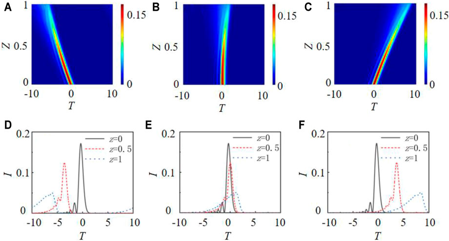
FIGURE 1. The propagation process of Airy pulse intensity at (A)υ = -3.6, (B)υ = 0, (C)υ = 3.6; The intensity distribution of Airy pulse after different distances at (D)υ = -3.6, (E)υ = 0 and (F)υ = 3.6.
At the same time, the longitudinal self-focusing propagation characteristics of a radially polarized circular Airy Gauss vortex in free space when R0= 2 is also analyzed. Figure 2A shows the longitudinal intensity distribution of incident light from Z = 0 to Z = 0.4. The dotted lines represent propagation positions at Z = 0, 0.1, 0.2, 0.3 and 0.4 successively. It can be found that the circular Airy Gauss vortex will focus at Z = 0.2, and the intensity peak will increase first rapidly and then decrease gradually versus the propagation distance, and the intensity maximum Imax= 5.515 at Z = 0.3.
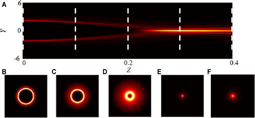
FIGURE 2. Longitudinal propagation characteristics of self-focusing of a radially-polarized circular Airy Gauss vortex bam in free space when R0= 2. (A) Longitudinal intensity distribution from Z = 0 to Z = 0.4 .(B)–(F) transverse intensity distribution of the beam at the dotted lines in (A).
Then the evolution of VSAi wave packet intensity during the focusing process can also be analyzed as in Figure 3. Where, I0 is the intensity extreme at the incident plane, and Imax/I0 represents the ratio of the intensity maximum during the propagation with the initial intensity extreme at the plane. It can be seen that the intensity of the VSAi wave packet can be enhanced with the symmetric incident Airy pulse pair in the time domain, and the intensity maximum at focus is about 80 times of that of the initial intensity. This provides a new idea to improve the pulse intensity at a specific position during the application of high intensity pulse processing.
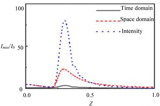
FIGURE 3. Variation of Imax/I0 of VSAi wave packet with the propagation distance.
Secondly, by decomposing the nonlinear Schrodinger equation and considering the third-order dispersion effect, we can get.
Where, b = β3/(|β2|bt) is the third-order dispersion coefficient. Then the influence of the third-order dispersion on the trajectory of the focused pulse can be analyzed by using the split step Fourier method. Figure 4 shows the influence of positive third-order dispersion coefficients on the evolution trajectory of the focused Airy pulse of T0 = 2 with the different third-order dispersion coefficients as (a) b = 0.1, (b) b = 0.2, (c) b = 0.3; (d) b = 0.4. It can be found that the positive third-order dispersion coefficient causes the forward propagation pulse to travel in the opposite direction, and positive third-order dispersion coefficient will cause a negative acceleration effect on the pulse. In addition, Table 1 shows the focusing position Z and the intensity peak Imax of the pulse for different positive third-order dispersion coefficients. We can see that the evolution trajectory of the focused pulse will deviate from the original trajectory versus the increasing of the third-order dispersion coefficient, the pulse will focus in advance during propagation, and the intensity peak of the focused pulse will also decrease. That’s because the increase of the third-order dispersion effect can result in the loss of pulse energy, and the decrease of the pulse energy at the focus will appear. Besides, T1 and Z1 in Figure 4A describe the change of the time and space position with the propagation pulse in the negative direction from the initial position to the focus for b > 0. Here the arctangent value of T/Z is defined as the deflection angle θ = arctan (T/Z) of propagation pulse, and it can be used to describe the influence of third-order dispersion effect on the deviation of the evolution trajectory. Figure 5A shows the variation of the pulse focusing position Z and deflection Angle θ versus the third-order dispersion coefficient b. It can be seen that the deflection angle of pulse evolution trajectory increases rapidly at first versus the increasing of b, but the growth rate tends to be flat after b = 0.4. The deflection angle of the pulse will increase by 0.2° for every 0.1 increasing of b for the case b < 0.4, but the deflection angle θ can’t reach 90° obviously, that’s because excessive third-order dispersion effecting will lead to excessive loss during the pulse propagation and failure to focus. Furthermore, the variation of the evolution trajectory deflection angle with the third-order dispersion coefficient can be approximately described as y = x1/2 by fitting, and the focusing position moving in the direction of Z = 0 with the increasing of the third-order dispersion coefficient. Figure 5B shows the variation of the pulse intensity maximum at the focus versus the third-order dispersion coefficient. The main peak intensity of the pulse at the focal point is closely related to the value of the wave packet equivalent surface. The intensity of the main peak at the focus of the pulse gradually decreases with increasing of b, and the intensity of the main peak at the focus is Imax= 0.2408 with b = 1. In conclusion, the deflection angle increases with the increasing of the third-order dispersion coefficients, but the focusing position will move toward Z = 0 and the intensity maximum will decrease.
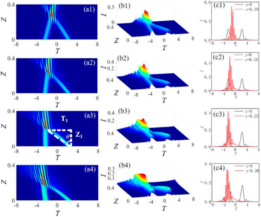
FIGURE 4. Propagation evolution and intensity distribution of the focused Airy pulse with initial interval T0 = 2 of the main lobe for different positive third-order dispersion coefficients (A) pulse intensity distributions (B) pulse evolution versus the propagation distance (C) intensity distributions of pulse at the initial plane Z = 0 and the focal point Z = 0.3.
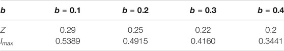
TABLE 1. Focusing position Z and intensity peak Imax of the pulse for different positive third-order dispersion coefficients.
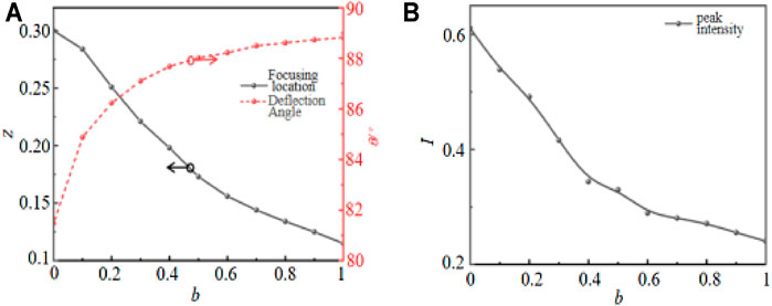
FIGURE 5. (A) Evolutions of focusing position and deflection angle versus third-order dispersion coefficients; (B) Variation of intensity maximum at the focal point versus b.
Based on the analysis above, Figure 6 presents the influence of negative third-order dispersion coefficients on the evolution trajectory of the focused Airy pulse of T0 = 2 with the different third-order dispersion coefficients as (a) b = -0.1, (b) b = -0.2, (c) b = -0.3 and (d) b = -0.4. It can be found that the negative third-order dispersion coefficient causes the reverse propagation pulse to travel in the positive direction, and negative third-order dispersion coefficient will have a positive acceleration effect on the pulse. In addition, Table 2 shows the focusing position Z and the intensity peak Imax of the pulse for different negative third-order dispersion coefficients. We can see that the focusing position and intensity maximum are not symmetrical with positive and negative third-order dispersion coefficients.
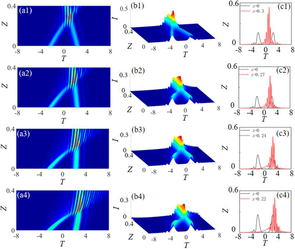
FIGURE 6. Propagation evolution and intensity distribution of the focused Airy pulse with initial interval T0 = 2 of the main lobe for different negative third-order dispersion coefficients (A) Pulse intensity distributions (B) pulse evolutions versus the propagation distance (C) intensity distributions of pulse at the initial plane Z = 0 and the focal point Z = 0.3.
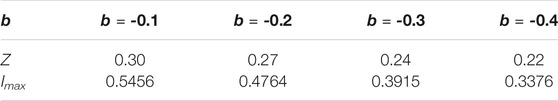
TABLE 2. Focusing position Z and intensity peak Imax of the pulse for different negative third-order dispersion coefficients.
Conclusion
Based on the nonlinear Schrodinger equation, we have established the spatiotemporal decoupling pulse propagation model of the vector field, and analyzed the influence of the initial time interval of focusing pulse on the pulse intensity maximum at the focus. Furthermore, we have also discussed the effects of the third-order dispersion effect at the focus and evolution trajectory of Airy pulses. It is found that the focused airy pulse with the third-order dispersion effect occupies more energy at the sub summit of the focus for the same initial intensity peak. The positive third-order dispersion coefficient causes the forward propagation pulse to travel in the opposite direction, and positive third-order dispersion coefficient will have a negative acceleration effect on the pulse. While the negative third-order dispersion coefficient causes the reverse propagation pulse to travel in the positive direction, and negative third-order dispersion coefficient will have a positive acceleration effect on the pulse. At the same time, it is also found that the intensity maximum of Airy pulse at the focus can be modulated by adjusting the third-order dispersion coefficient, and the evolution trajectory of the pulse can be accurately controlled and processed by adjusting the third-order dispersion effect. In paraxial optical system, the propagation along the Z direction in free space of spatiotemporal decoupled wave packets can be described by the normalized Schrodinger equation. Decoupling the three-dimensional (3D) wave packet as a fundamental spatiotemporal element requires a one-dimensional dispersion-free pulse, that means the wave packet can be decoupled spatiotemporal without dispersion modulation of the pulse, and the spatiotemporal computation can be carried out independently. These results can provide a theoretical basis for accurately controlling the evolution trajectory and intensity peak of the spatiotemporal self-focusing wave packet.
Data Availability Statement
The original contributions presented in the study are included in the article/supplementary material, further inquiries can be directed to the corresponding authors.
Author Contributions
Authors DL, XC, and CW are mainly engaged in the calculation and analysis of paper data, as well as the writing and modification of papers. PL and JZ are mainly engaged in the modification and polishing of the paper.
Funding
National Key Research and Development Program of China (2017YFA0303800); National Natural Science Foundation of China (61975165, 61405163); Aeronautical Science Foundation of China (201934053001); Natural Science Basic Research Plan in Shaanxi Province of China (2018JQ6029); Fundamental Research Funds for the Central Universities (310201911cx020, 3102017zv019).
Conflict of Interest
The authors declare that the research was conducted in the absence of any commercial or financial relationships that could be construed as a potential conflict of interest.
Publisher’s Note
All claims expressed in this article are solely those of the authors and do not necessarily represent those of their affiliated organizations, or those of the publisher, the editors and the reviewers. Any product that may be evaluated in this article, or claim that may be made by its manufacturer, is not guaranteed or endorsed by the publisher.
References
1. McLeod R, Wagner K, Blair S. (3+1)-dimensional Optical Soliton Dragging Logic. Phys Rev A (1995) 52(4):3254–78. doi:10.1103/PhysRevA.52.3254
2. Li D, Chen X, Yang Z, Zhang W, Zhao J. Velocity Property of an Optical Chain Generated by the Tightly Focused Femtosecond Radially Polarization Pulse. Appl Opt (2021) 60(8):2380–7. doi:10.1364/AO.418310
3. Papasimakis N, Raybould T, Fedotov VA, Tsai DP, Youngs I, Zheludev NI. Pulse Generation Scheme for Flying Electromagnetic Doughnuts. Phys Rev B (2018) 97(20):201409. doi:10.1103/PhysRevB.97.201409
4. Shen Y, Hou Y, Papasimakis N, Zheludev N. Supertoroidal Light Pulses: Propagating Electromagnetic Skyrmions in Free Space. arXiv:2103.08431 (2021). doi:10.21203/rs.3.rs-345437/v1
5. Bliokh KY. Spatiotemporal Vortex Pulses: Angular Momenta and Spin-Orbit Interaction. Phys Rev Lett (2021) 126. doi:10.1103/PhysRevLett.126.243601
6. Shen Y, Zdagkas A, Papasimakis N, Zheludev NI. Measures of Space-Time Nonseparability of Electromagnetic Pulses. Phys Rev Res (2021) 3. doi:10.1103/physrevresearch.3.013236
7. Zdagkas A, Shen Y, Mcdonnell C, Deng J, Li G, Ellenbogen T, et al. Observation of Toroidal Pulses of Light. arXiv:2102.03636 (2021).
8. Hellwarth RW, Nouchi P. Focused One-Cycle Electromagnetic Pulses. Phys Rev E (1996) 54:889–95. doi:10.1103/physreve.54.889
9. Berry MV, Balazs NL. Nonspreading Wave Packets. Am J Phys (1979) 47(4):264–7. doi:10.1119/1.11855
10. Ring JD, Lindberg J, Mourka A, Mazilu M, Dholakia K, Dennis MR. Auto-focusing and Self-Healing of Pearcey Beams. Opt Express (2012) 20(17):18955–66. doi:10.1364/OE.20.018955
11. Ren Z, Fan C, Shi Y, Chen B. Symmetric Form-Invariant Dual Pearcey Beams. J Opt Soc Am A (2016) 33(8):1523–30. doi:10.1364/JOSAA.33.001523
12. Zhijun R, Chaofu Y, Hongzhen J, Bo C. Generation of a Family of Pearcey Beams Based on Fresnel Diffraction Catastrophes. J Opt (2015) 17(10):105608. doi:10.1088/2040-8978/17/10/105608
13. Liu X-L, Lu X, Liu X, Feng L-B, Ma J-L, Li Y-T, et al. Broadband Supercontinuum Generation in Air Using Tightly Focused Femtosecond Laser Pulses. Opt Lett (2011) 36(19):3900–2. doi:10.1364/OL.36.003900
14. Wang H, Shi L, Lukyanchuk B, Sheppard C, Chong CT. Creation of a Needle of Longitudinally Polarized Light in Vacuum Using Binary Optics. Nat Photon (2008) 2(8):501–5. doi:10.1038/nphoton.2008.127
15. Youngworth KS, Brown TG. Focusing of High Numerical Aperture Cylindrical-Vector Beams. Opt Express (2000) 7(2):77–87. doi:10.1364/OE.7.000077
16. Siviloglou GA, Broky J, Dogariu A, Christodoulides DN. Observation of Accelerating Airy Beams. Phys Rev Lett (2007) 99(21):213901. doi:10.1103/PhysRevLett.99.213901
17. Eichelkraut TJ, Siviloglou GA, Besieris IM, Christodoulides DN. Oblique Airy Wave Packets in Bidispersive Optical media. Opt Lett (2010) 35(21):3655–7. doi:10.1364/OL.35.003655
18. Zhong W-P, Belić MR, Huang T. Three-dimensional Finite-Energy Airy Self-Accelerating Parabolic-cylinder Light Bullets. Phys Rev A (2013) 88(3):2974–81. doi:10.1103/PhysRevA.88.033824
19. Zhong W-P, Belić M, Zhang Y. Three-dimensional Localized Airy-Laguerre-Gaussian Wave Packets in Free Space. Opt Express (2015) 23(18):23867–76. doi:10.1364/OE.23.023867
20. Peng X, Peng Y, Li D, Zhang L, Zhuang J, Zhao F, et al. Propagation Properties of Spatiotemporal Chirped Airy Gaussian Vortex Wave Packets in a Quadratic index Medium. Opt Express (2017) 25(12):13527–38. doi:10.1364/OE.25.013527
21. Chong A, Renninger WH, Christodoulides DN, Wise FW. Airy-Bessel Wave Packets as Versatile Linear Light Bullets. Nat Photon (2010) 4(2):103–6. doi:10.1038/nphoton.2009.264
22. Driben R, Meier T. Nonlinear Dynamics of Airy-Vortex 3D Wave Packets: Emission of Vortex Light Waves. Opt Lett (2014) 39(19):5539–42. doi:10.1364/OL.39.005539
23. Deng F, Deng D. Three-dimensional Localized Airy-Hermite-Gaussian and Airy-Helical-Hermite-Gaussian Wave Packets in Free Space. Opt Express (2016) 24(5):5478–86. doi:10.1364/OE.24.005478
Keywords: vector beam, vortex, wave packets, optical pulse, dispersion
Citation: Li D, Chen X, Wei C, Li P and Zhao J (2021) Dispersion Characteristic of Spatiotemporal Sharply Autofocused Vector Airy-Circular Airy Gaussian Vortex Wave Packets. Front. Phys. 9:751963. doi: 10.3389/fphy.2021.751963
Received: 02 August 2021; Accepted: 20 September 2021;
Published: 04 October 2021.
Edited by:
Zhi-Han Zhu, Harbin University of Science and Technology, ChinaReviewed by:
Yijie Shen, University of Southampton, United KingdomPei Zhang, Xi’an Jiaotong University, China
Copyright © 2021 Li, Chen, Wei, Li and Zhao. This is an open-access article distributed under the terms of the Creative Commons Attribution License (CC BY). The use, distribution or reproduction in other forums is permitted, provided the original author(s) and the copyright owner(s) are credited and that the original publication in this journal is cited, in accordance with accepted academic practice. No use, distribution or reproduction is permitted which does not comply with these terms.
*Correspondence: Dong Li, ZG9uZ2xpQG53cHUuZWR1LmNu; Jianlin Zhao, amx6aGFvQG53cHUuZWR1LmNu