 Wei Shi
 Zhiquan Wang
 Lei Hou
 Haiqing Wang
- The Key Laboratory of Ultrafast Photoelectric Technology and Terahertz Science in Shaanxi, Xi’an University of Technology, Xi’an, China
A 2 × 2 terahertz photoconductive antenna (PCA) array detector with high efficiency synthesis characteristic that improves the signal-to-noise ratio (SNR) of the detected signals has been reported in this paper. By processing the substrate material through a special micromachining process, the current signal generated by the adjacent antenna elements as opposed to that generated by the antenna gap is eliminated. Experiments show that the amplitude of the current signal output by the PCA array detector is consistent with the amplitude of the synchronous superposition of the current signals output by antenna elements, and the synthesis efficiency of the device achieves 93.7%. At the same time, the antenna array detector has low current noise, and its highest SNR is 62 dB under the excitation of different light energy, which is related to the number of antenna array elements.
Introduction
There are mainly two ways to detect terahertz (THz) time-domain waveforms: electro-optic (EO) crystal and photoconductive antenna. The principle of the former is based on the Pockels effect of crystals [1, 2]. A thinner EO crystal can provide a wider spectrum, but at the same time it leads to a decrease in detection sensitivity [3]. Compared with the photoconductive antennas, the EO detection requires more optical elements, higher cost and larger system size. THz waves detection by PCAs is the inverse process of the THz waves generation by PCAs. The performances of large spectral width, small size and ease of use make photoconductive antennas attractive for commercialization. In addition, pasting a silicon lens on the back of antennas will improve the detector’s ability to collect THz waves and obtain a higher SNR [4]. Although a single THz PCA has been widely used in THz time-domain spectroscopy systems, it still has shortcomings in detecting weak terahertz signals and improving the SNR. In theory, connecting multiple PCAs in parallel to form a PCA array detector can make use of the THz electric field as much as possible to improve the SNR and detection sensitivity of the PCA array detector. Although the PCA array detector with hundreds to thousands antenna elements have been proposed and developed [5, 6], the synthesis efficiency of PCA array was not discussed in detail in the previous work, which is important to improve the detection efficiency. When the PCA array is used as a detector, it faces the same problem when it is used as an emitter. That is, the photo-generated carriers generated in the substrate materials between adjacent antennas move directionally under the action of the terahertz electric field, forming a current opposite to the current generated in the antenna gap, the reverse current will reduce the generation efficiency of THz waves. The same phenomena will also reduce the synthesis efficiency of the PCA array detector [7]. At present, techniques to avoid the reverse current between adjacent antenna elements include employing shielding substrate between adjacent elements or using a micro-lenses array to split and focus the probe beams on the gaps [8, 9]. However, electrons transition from the valence band to the conduction band with the excitation of laser, the electrons generated in the antenna gap still can move to other antenna gaps due to the diffusion motion and the drift motion in response to the THz electric field. Therefore, these solutions cannot fundamentally solve the problem of reverse current between antenna elements.
In this work, a THz PCA array detector that eliminates the reverse current between the adjacent antenna elements is designed and fabricated, and its outstanding synthesis efficiency and signal-to-noise ratio have been demonstrated by comparing with a single antenna element.
Antenna Design and Experimental Setup
Antenna Design
The structure diagram of the 2 × 2 PCA array detector is shown in Figure 1A. Its substrate is low-temperature-grown GaAs (LT-GaAs) with a thickness of 1 μm grown on (100) semi-insulating (SI)-GaAs at 250°C using MBE system. AuGeNiAu electrodes were deposited on the substrate by e-beam evaporation, and was metalized by rapid annealing to form an ohmic contact. The antenna element has a dipole length (L) of 250 μm, a dipole gap (g) of 50 μm, a dipole antenna width (d) of 30 μm, an electrode width (w) of 370 μm, and an electrode length (h) of 990 μm. The activation area of antenna element is 0.03 mm × 0.05 mm and the distance between adjacent antenna elements is about 10 μm. The pickup circuit designed in the experiment can not only output the synthetic signal of a PCA array detector, but also each signal of each antenna element by connecting different output ports.
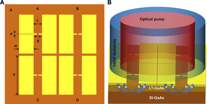
FIGURE 1. Construction and use of 2 × 2 photoconductive antenna array: (A) Design structure of 2 × 2 photoconductive antenna array. (B) Schematic diagram of irradiation by laser and terahertz wave.
Experimental Setup
In this paper, a THz time-domain spectroscopy system is used for measure the performance of the THz PCA array detector. A Ti:sapphire laser (Spectra-physics, MaiTai XF–1) with a center wavelength of 800 nm, a pulse width of 70 fs, and a repetition frequency of 80 MHz is used to excite the detector and the emitting antenna. The LT-GaAs PCA emitter with a gap of 150 μm was excited by a pump beam with the power of 200 mW and the voltage applied to the emitter was 300 V. The polarization direction of the THz electric field was parallel to the electrode gaps of the PCA array detector. The THz wave was focused on the PCA array detector through an off-axis parabolic mirror, and the diameter of focused THz beam measured by the knife edge method is 2.09 mm. The probe beam was focused to a spot with the diameter of 3 mm on the PCA array detector. The THz pulse and the laser pulse illuminate the PCA array detector vertically on the same side, as shown in Figure 1B. The output signal was recorded by a lock-in amplifier (SR830).
Results
In order to explain that photo-generated carriers move freely throughout the semiconductor, an unmicromachined antenna array, which is similar to the interdigitated PCA detectors, was used for the verification experiment, we focused the laser with a power of 800 mW laser on the gap of one antenna element, and the diameter of the focus is 93 μm, the dark state resistance of the antenna was reduced from 1.1 GΩ to several MΩ. The resistance of other antenna elements in the unlit area was reduced by two orders of magnitude. In addition, the resistance between adjacent antenna elements was also reduced by two orders of magnitude, indicating that the photo-generated carriers generated in one antenna gap are not limited to movement in this antenna gap. On the contrary, due to the THz electric field, the reverse current can be formed between the adjacent antenna elements, which causes the synthesis efficiency of the PCA array detector decrease. Therefore, the masking process between the array elements for the interdigitated PCA array detector cannot prevent the reverse current between the array elements. In this experiment, we cutting the substrate material of adjacent elements by high power laser, and rearranged the elements with proper distance to eliminate the reverse current between adjacent antenna elements, and the photo-generated carriers generated by the antenna elements were restricted from moving to other antennas. When one antenna element was triggered by laser, the resistance of other antenna elements does not change.
When the PCA array detector was excited by the probe beam with the power of 120 mW, the THz time-domain waveforms of the each antenna element and PCA array detector are shown in Figure 2A. The amplitude of THz time domain waveform of the PCA array detector is far greater than that of the antenna elements A, B, C and D when they work alone. Due to the difference of the antenna elements’ performance and the uneven irradiation of laser and THz waves, the amplitudes of the time-domain waveforms output from each element antenna are different. At the same time, there is a time difference among the waveforms of antenna elements, and the largest one is about 300 fs between A and D. The reason is caused by the optical path difference between the probe beam and the THz beam received by each antenna element.
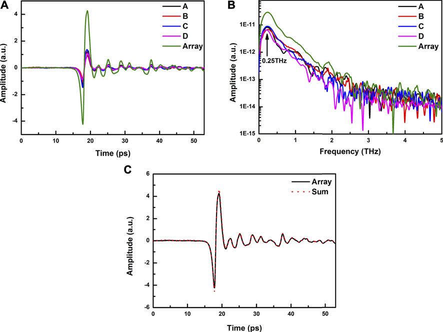
FIGURE 2. Terahertz wave was detected by photoconductive antenna array: (A) Time-domain signals of antenna elements and array; (B) Frequency domain signals of antenna elements and array; (C) Synthesis efficiency of the antenna array.
In addition, the bandwidth of the PCA array is same as that of the antenna elements. The resonant frequency of the antenna elements is the same as that of the antenna array, and all of them are 0.25 THz, which is marked in Figure 2B.
The output photocurrent of the PCA array detector under THz wave excitation can be calculated as,
Where, e is the electronic charge, μ is the electron mobility of LT-GaAs, ETHz is the incident THz electric field, and Ni(t) is the number of photo-generated carriers on the ith photoconductive antenna element. Due to the low carrier lifetime of LT-GaAs,
Where n is the number of element antennas,
Generally, the output noise current of the photoconductive detector mainly comes from Johnson-Nyquist noise and shot noise [12, 13]. The root mean square (RMS) value of the noise current output form the symmetrically pumped PCA array detector is as follows:
where kB is the Boltzmann constant, T is operation temperature in kelvin, hν is the energy of the probe photons, ηe is the photoconductor external quantum efficiency, τn and τp are lifetimes of electrons and holes in the semiconductor, μn and μp are electron and hole mobility, P0 is the DC component of the envelope surface of the optical probe, and Δf is the detection bandwidth. The data of RMS noise of the antenna elements and PCA array are listed in Table 1. The noise of the array antenna is lower than the average noise of the elements, that means the PCA array plays the role in reducing the overall noise.
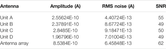
TABLE 1. The amplitude and RMS noise of the time domain signal of the antenna elements and the array detector.
Figure 3A and Figure 3B show the time-domain waveforms and frequency-domain spectra detected by the PCA array detector under different probe power, the signal amplitude increases with the increase of the probe power. When the probe power is only 1 mW, the PCA array detector still shows a good response curve. When the probe power increases from 1mW to 120 mW, the THz linear increases. When the probe power is greater than 120 mW, the amplitude tends to be saturated. This saturation is caused by the screening effect, which is related to the carrier density generated on the GaAs surface. The influence of the screening effect on the PCA emitter has been reported [14, 15], and its influence on the PCA detector can be expressed as [16].
ETHz(t) is the incident THz electric field, ε and α are the dielectric constant and geometric factor of GaAs, respectively. P(t) is the polarization caused by the separation of electron-hole pairs, and it increases as the density of photo-generated carrier increases. The detection bandwidth of the PCA array detector is about 2.5 THz, which is the same as that of a single antenna. At the same time, the noise data of the detector was measured while the terahertz source was working normally. The SNR is proportional to the laser power when the probe power is lower than 120 mW, and the maximum SNR of the detector reaches 62 dB at 120 mW. When the power of probe beam exceeds 120 mW, the noise of the detection current increases and the SNR decreases due to the carrier shielding effect, as is shown in Figure 3Cand Figure 3D.
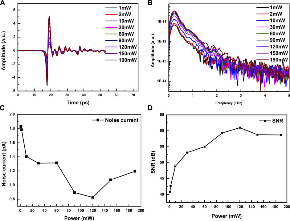
FIGURE 3. The response of the PCA array detector under different probe power. (A) Time-domain spectrum; (B) Frequency domain spectrum; (C) The noise current of the PCA array detector; (D) SNR of the PCA array detector.
Conclusion
In summary, we proposed a PCA array detector with high synthesis efficiency. According to experimental verification and theoretical analysis, the reverse current between the array elements is eliminated, and the synthesis efficiency of the PCA array detector reaches 93.7%. At the same time, the results show that the detector has a low noise, which is lower than the average noise of the elements. The bandwidth of the PCA array detector is about 2.5 THz. Within the probe power of 0–120 mW, the THz amplitude of detector shows a linear growth trend. When the probe power exceeds 120 mW, the signal amplitude tends to be saturated and the current noise increases due to the carrier shielding effect. The detector has a maximum SNR of 62 dB at the probe power of 120 mW power. The concept of the proposed PCA array detector can be widely used in both large size and small size PCA array detector to improve its detection efficiency.
Data Availability Statement
The raw data supporting the conclusions of this article will be made available by the authors, without undue reservation.
Author Contributions
Conceptualization, WS; methodology, LH; formal analysis, ZW; data curation, MW and CL; writing—original draft preparation, ZW; writing—review and editing, WS. All authors have read and agreed to the published version of the manuscript.
Funding
This research was funded by the National Key Research and Development Program of China (Grant No. 2017YFA0701005), the National Natural Science Foundation of China (Grant No. 51807161, Grant No. 62075179), the Natural Science Foundation of Shaanxi Province (Grant No. 2019JZ-04), Special Scientific Research Plan of Shaanxi Provincial Education Department, China (Grant No. 19JK0297).
Conflict of Interest
The authors declare that the research was conducted in the absence of any commercial or financial relationships that could be construed as a potential conflict of interest.
Publisher’s Note
All claims expressed in this article are solely those of the authors and do not necessarily represent those of their affiliated organizations, or those of the publisher, the editors and the reviewers. Any product that may be evaluated in this article, or claim that may be made by its manufacturer, is not guaranteed or endorsed by the publisher.
References
1. Wu Q, Zhang X-C. Free-space Electro-Optics Sampling of Mid-infrared Pulses. Appl Phys Lett (1997) 71(10):1285–6. doi:10.1063/1.119873
2. Neu J, Schmuttenmaer CA. Tutorial: An Introduction to Terahertz Time Domain Spectroscopy (THz-TDS). J Appl Phys (2018) 124(23):231101. doi:10.1063/1.5047659
3. Han PY, Zhang X-C. Coherent, Broadband Midinfrared Terahertz Beam Sensors. Appl Phys Lett (1998) 73(21):3049–51. doi:10.1063/1.122668
4. Formanek F, Brun M-A, Umetsu T, Omori S, Yasuda A. Aspheric Silicon Lenses for Terahertz Photoconductive Antennas. Appl Phys Lett (2009) 94(2):021113. doi:10.1063/1.3072357
5. Dreyhaupt A, Winnerl S, Dekorsy T, Helm M. High-intensity Terahertz Radiation from a Microstructured Large-Area Photoconductor. Appl Phys Lett (2005) 86(12):121114–2756. doi:10.1063/1.1891304
6. Dreyhaupt A, Winnerl S, Helm M, Dekorsy T. Optimum Excitation Conditions for the Generation of High-Electric-Field Terahertz Radiation from an Oscillator-Driven Photoconductive Device. Opt Lett (2006) 31(10):1546. doi:10.1364/OL.31.001546
7. Hattori T, Egawa K, Ookuma SI, Itatani T. Intense Terahertz Pulses from Large-Aperture Antenna with Interdigitated Electrodes. Jpn J Appl PhysicsLetters Express Lett (2006) 45(No. 15):L422–L424. doi:10.1143/jjap.45.l422
8. Yardimci NT, Jarrahi M. High-performance terahertz detectors based on plasmonic nano-antennas[ [Conference presentation]. In: 41st International Conference on Infrared, Millimeter, and Terahertz waves (IRMMW-THz), Copenhagen, September, 2016. (Denmark: IEEE) (2016):1–2. doi:10.1109/irmmw-thz.2016.7758867
9. Pradarutti B, Müller R, Freese W, Matthäus G, Riehemann S, Notni G, et al. Terahertz Line Detection by a Microlens Array Coupled Photoconductive Antenna Array. Opt Express (2008) 16(22):18443–50. doi:10.1364/oe.16.018443
10. Shen YC, Upadhya PC, Beere HE, Linfield EH, Davies AG, Gregory IS, et al. Generation and Detection of Ultrabroadband Terahertz Radiation Using Photoconductive Emitters and Receivers. Appl Phys Lett (2004) 85(2):164–6. doi:10.1063/1.1768313
11. Tani M, Sakai K, Mimura H. Ultrafast Photoconductive Detectors Based on Semi-insulating GaAs and InP. Jpn J Appl Phys (1997) 36(Part 2, No. 9A/B):L1175–L1178. doi:10.1143/jjap.36.l1175
12. Wang N, Jarrahi M. Noise Analysis of Photoconductive Terahertz Detectors. J Infrared Milli Terahz Waves (2013) 34(9):519–28. doi:10.1007/s10762-013-9995-1
13. Hou L, Shi W. An LT-GaAs Terahertz Photoconductive Antenna with High Emission Power, Low Noise, and Good Stability. IEEE Trans Electron Devices (2013) 60(5):1619–24. doi:10.1109/ted.2013.2253467
14. Murakami H, Fujiwara S, Kawayama I, Tonouchi M. Study of Photoexcited-Carrier Dynamics in GaAs Photoconductive Switches Using Dynamic Terahertz Emission Microscopy. Photon Res (2016) 4(3):A9–A15. doi:10.1364/prj.4.0000a9
15. Awad M, Nagel M, Kurz H, Herfort J, Ploog K. Characterization of Low Temperature GaAs Antenna Array Terahertz Emitters. Appl Phys Lett (2007) 91(18):181124. doi:10.1063/1.2800885
Keywords: terahertz wave, antenna array, signal-to-noise ratio, synthesis, reverse current
Citation: Shi W, Wang Z, Hou L, Wang H, Wu M and Li C (2021) A High Performance Terahertz Photoconductive Antenna Array Detector With High Synthesis Efficiency. Front. Phys. 9:751128. doi: 10.3389/fphy.2021.751128
Received: 31 July 2021; Accepted: 25 August 2021;
Published: 08 September 2021.
Edited by:
Yingxin Wang, Tsinghua University, ChinaCopyright © 2021 Shi, Wang, Hou, Wang, Wu and Li. This is an open-access article distributed under the terms of the Creative Commons Attribution License (CC BY). The use, distribution or reproduction in other forums is permitted, provided the original author(s) and the copyright owner(s) are credited and that the original publication in this journal is cited, in accordance with accepted academic practice. No use, distribution or reproduction is permitted which does not comply with these terms.
*Correspondence: Wei Shi, c3dzaGlAbWFpbC54YXV0LmVkdS5jbg==