 Yunpeng Liu1†
 Xingpeng Yan
95% of researchers rate our articles as excellent or good
Learn more about the work of our research integrity team to safeguard the quality of each article we publish.
Find out more
ORIGINAL RESEARCH article
Front. Phys. , 24 August 2021
Sec. Optics and Photonics
Volume 9 - 2021 | https://doi.org/10.3389/fphy.2021.736268
This article is part of the Research Topic Digital Holography: Techniques and Applications View all 16 articles
In this paper, an optical field coding method for the fusion of real and virtual scenes is proposed to implement an augmented reality (AR)-based holographic stereogram. The occlusion relationship between the real and virtual scenes is analyzed, and a fusion strategy based on instance segmentation and depth determination is proposed. A real three-dimensional (3D) scene sampling system is built, and the foreground contour of the sampled perspective image is extracted by the Mask R-CNN instance segmentation algorithm. The virtual 3D scene is rendered by a computer to obtain the virtual sampled images as well as their depth maps. According to the occlusion relation of the fusion scenes, the pseudo-depth map of the real scene is derived, and the fusion coding of 3D real and virtual scenes information is implemented by the depth information comparison. The optical experiment indicates that AR-based holographic stereogram fabricated by our coding method can reconstruct real and virtual fused 3D scenes with correct occlusion and depth cues on full parallax.
A holographic stereogram [1–3] is an effective three-dimensional (3D) display technology. It combines traditional optical holography [4] with the parallax effect [5] and can realize high-resolution and wide-viewing-angle 3D naked eye display of 3D scenes, which is considered the ultimate form of 3D display technology [6, 7]. A holographic stereogram takes advantage of the limited resolution of human eyes, and it can express continuous and realistic 3D optical field information with a limited 2D perspective sequence, the parallax information of which is less than the resolving power of human eyes. The amount of data sampling and processing loss are small. 2D perspective images are not the only data source, but the reconstruction image and the formation of stereo vision also come from the difference of information received by human eyes. Therefore, the scene data source suitable for holographic stereogram is more universal and flexible, and the 3D optical field information it can express is more abundant and diverse. For real scenes, a camera array or motion camera can be used for capturing and sampling, which can realize the display of large-format scenes. For 3D models rendered by a computer, one can use software to realize 3D cues such as occlusion, shadow, and transparency between scenes. It is worth mentioning that, on some occasions, the fusion of real and virtual scenes in 3D display may be more valuable. For example, in the exhibition of cultural relics, in order to display the 3D image and specific information of cultural relics while protecting cultural relics, some virtual introductory signs can be superimposed on the image of cultural relics. Obviously, this kind of holographic 3D display can enhance people’s perception of the 3D world and achieve the effect of augmented reality (AR). In order to make this kind of holographic stereogram, the real and virtual scenes must be sampled separately, and the optical field information must be encoded and holographically printed according to the required spatial position relationship, so as to realize the AR display based on holographic stereo vision.
In traditional AR display, virtual information such as text, images, and 3D models generated by a computer is simulated and superimposed on the real world. The two kinds of information complement each other, so as to realize the “enhancement” of the real world. Generally, it does not need to encode and reconstruct the real scene. Deng et al. used a reflective polarizer (RP) to realize AR 3D display, which has potential applications in stomatology and vehicle AR display [8]. Shi et al. demonstrated a convolutional neural network (CNN)-based computer-generated holographic (CGH) pipeline capable of synthesizing a photorealistic color 3D hologram from a single RGBD image in real time [9]. Maimone et al. presented designs for virtual reality (VR) and AR near-eye displays based on phase-only holographic projection, which not only fix minor aberrations but also enable truly compact, eyeglass-like displays with wide fields of view (80°) [10]. Yang et al. proposed a fast CGH method with multiple projection images for a near-eye VR and AR 3D display by convoluting the projection images with the corresponding point spread function (PSF) [11]. In 2012, Google released Google Project Glass that can display an operation interface similar to smart phones, and people can operate it through sound or touch sensing devices [12]. In 2015, Microsoft released an AR head-mounted display that can interact with people through gestures and that is expected to realize the sense of technology visualized in some science fiction movies [13].
However, in the field of holographic stereograms, there is little research on the AR display of 3D scenes. Drawing on the experience of AR, the main task of AR 3D display of holographic stereograms is to implement the fusion coding of 3D real and virtual scenes information. Moreover, the key to fusion lies in the correct expression of the occlusion relationship between scenes. Three methods exist to deal with the problem of real and virtual scenes occlusion: model-based, depth-based, and image analysis-based methods.
The model-based method is used to reconstruct the 3D model of the real scene by a computer and then export the model data and render the virtual scene at the same time to achieve the fusion effect. This method was first proposed by Breen in 1996, but it was difficult to realize due to the technical conditions at that time [14]. Ong et al. presented a 3D reconstruction approach using a structure from motion (SFM) algorithm to obtain the real scene 3D model, avoiding the huge workload of traditional modeling [15]. Newcombe et al. designed a 3D reconstruction system that can transmit 3D information accurately and in real time [16]. The system uses a Kinect sensor to obtain the depth information of the real scenes and uses GPU parallel computing for real-time reconstruction and fusion rendering. The depth-based method is used to determine the occlusion relationship according to the depth value of the object point and usually only displays the information of the near object point. Wloka et al. proposed a video see-through AR system capable of resolving occlusion between real and computer-generated objects, which calculates the pixel depth value through a stereo matching algorithm and compares the depth value to determine the position relationship between real and virtual scenes [17]. Some researchers use hardware devices to calculate depth. Jesus et al. introduced a depth-of-flight range sensor into AR to obtain the depth map and then judged the visibility of the fusion scene [18]. The method based on image analysis, which was proposed by Berger in 1997 [19], is to first detect the edge of the real scene image, draw an accurate contour, and then manually mark and complete the occlusion relationship between the real and virtual scenes. This method relies on the superiority of the edge detection algorithm, and each image must be marked manually; so, it cannot guarantee real-time performance. Many researchers have proposed background extraction and target contour fusion, but the results are not accurate [20–22]. Roxas et al. used a CNN-based semantic segmentation algorithm to obtain more accurate foreground segmentation results. Moreover, according to the complexity of object boundary and texture, labels are assigned to the real scene, which improves the automation performance [23].
The model-based method can better express the occlusion relationship by putting the real and virtual scenes into the same time and space, but there is a certain degree of information loss in using a 3D model to express the real light field, which will cause the real scene to be unreal. In theory, the depth-based method can effectively deal with more complex occlusion relationships, but, in practice, the accurate calculation of a depth map is not easy, and there are some other problems, such as limited range, dependence on lighting conditions, and sparsity of data points. The method based on image analysis not only keeps the authenticity of the real light field but also does not need to calculate the accurate depth value. However, it usually needs manual marking and has a low degree of automation.
In this paper, we reference the method based on image analysis and use the Mask R-CNN [24] instance segmentation algorithm to extract the contour of the real scene. To reduce the manual marking part and improve the automation of the image analysis-based method, we use the results of an instance segmentation algorithm to give a pseudo-depth-value to each instance according to the occlusion relationship, and then the depth-based method is applied to encode the optical field to achieve the effective fusion when the virtual scene and real scene have a mutual occlusion relationship. The principle and implementation details of the optical field coding method are introduced. The encoded images are processed by the effective perspective images’ segmentation and mosaicking (EPISM) printing method [25, 26]. Optical experiments show that the method proposed in this paper can effectively realize AR 3D display of holographic stereogram. Finally, we analyze and discuss the reconstructed optical field in detail.
The scene’s information fusion coding of an AR-based holographic stereogram cannot be simply obtained by superimposing virtual 3D scenes onto the real scenes. The real and virtual scenes should have a reasonable or even complex occlusion relationship, so that the observer can have a good and real visual experience that can reconstruct the real and virtual fused 3D scenes correctly.
Figure 1, taking a simple real and virtual fused 3D scene as an example, shows a real 3D scene
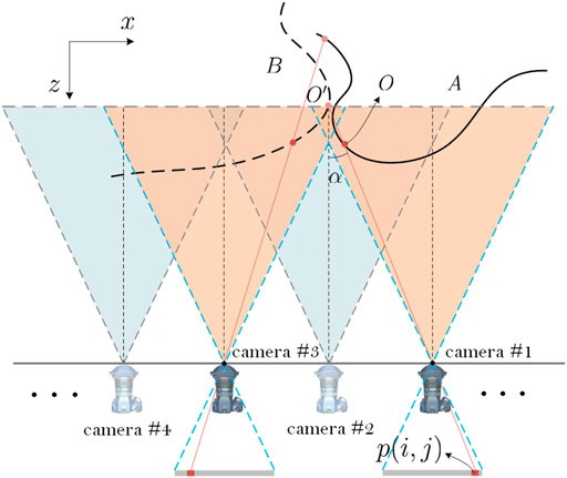
FIGURE 1. Analysis of occlusion relationship between real and virtual scene.
The fused image from a certain perspective can be expressed as:
where
The above is the basic principle of the depth-based method, in which the process of solving the depth information
The principle of the depth-based method shows that the main reason for occlusion in the fusion images between the real and virtual 3D scenes is the difference of object point depth information in a certain ray. The point with a small depth blocks the point with a large depth and leaves the intensity information at the corresponding pixels of the fusion image. However, the decision condition is only to compare the value of the depth and does not require the specific depth value, which provides the opportunity to improve the depth-based method.
Referring to Figure 2,
where

FIGURE 2. Correspondence between pixels and points in optical field fusion.
In terms of technical difficulty, instance segmentation is simpler than accurate depth calculation. Next, combined with the actual application of the scene in this paper, the real and virtual scene image fusion coding strategy is introduced in detail.
Figure 3 shows the fusion strategy of real and virtual scenes for holographic stereogram AR 3D display. Taking the perspective
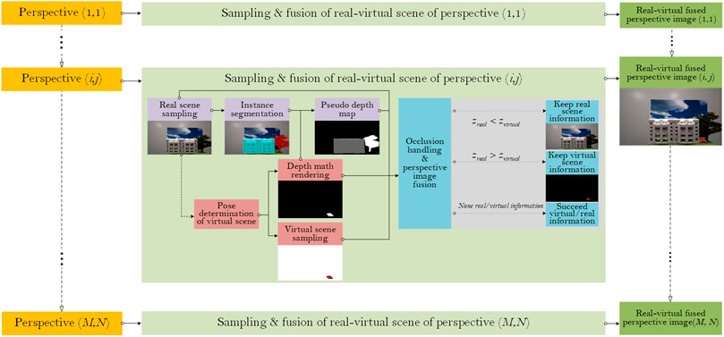
FIGURE 3. Fusion strategy of real and virtual scenes.
Step 1: Real scene sampling. Obtain the real scene sampling perspective sequence. The instance segmentation algorithm is used to segment different instances in the scene. Furthermore, the real scene sampling images
where the three terms on the right-hand side of the equation represent the light field sampling information of the house, tree, and background in
Step 2: According to the scene space position and camera pose adjustment in Step 1, the virtual scene sampling parameters are set. The sampled image
where
where
Step 3: According to the occlusion relationship and the depth map of the virtual scene, the pseudo-depth-value is assigned to each instance after the instance segmentation, and the value of
where
Step 4: The fusion of real and virtual optical fields. According to the depth-based method, the near information in the fusion scene is retained in the processed image, as shown in
Note that
According to the above-mentioned four steps, we gradually realized the effective coding of real and virtual scene optical fields and carried out the detail display and result analysis.
In our work, we used the “house and tree” model as the foreground objects of the real scene and the “sky” as the background (see Figure 4B). A single camera timing sampling system was built to sample the real scene’s perspective information. A single MER2-502-79U3C CMOS digital camera was fixed on a Zolix KSA300 electronic control displacement platform. The stepper motor in the displacement platform was driven by a Zolix MC600 motion controller, which could realize arbitrary interval shift sampling in both the horizontal and vertical directions, as shown in Figure 4A.
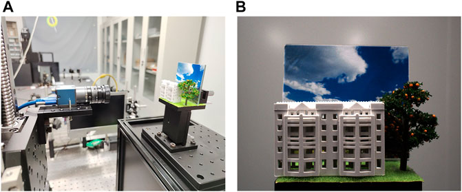
FIGURE 4. (A) Single camera timing sampling system (B) real scene image.
After comprehensive comparison of several instance segmentation methods, we used the better Mask R-CNN instance segmentation network architecture for processing. Mask R-CNN can realize target detection, semantic segmentation, and instance segmentation. Fast R-CNN (an excellent target detection network architecture) adds a full convolution network (FCN), realizes semantic segmentation on the basis of target detection, and then realizes instance segmentation [38]. It adds a layer of random color mask to the specified instance. Using the Windows operating system and the efficient computing power of an NVIDIA TITAN XP graphics card, we built a Mask R-CNN network architecture based on the Keras2.1.5 model library on the Tensorflow 1.13.2 deep-learning open-source framework. A dataset of 400 real scene images with mask labels was produced by using the “labelme” annotation tool (the total number of images to be encoded was 4,761), of which 350 were used for training and 50 for validation. We set the training times to 150 epochs. After the iterative optimization training of the multi-layer feature pyramid network, the training set loss was reduced to 0.017, the validation set loss was reduced to 0.016, and the confidence of the target detection accuracy was close to 1.0. Figures 5A,B show the sampled images and labeled masked label in the experiment respectively. The test effect on the self-made dataset is shown in Figure 5C. Details of the occlusion mask are shown. The main part of the house model was completely covered, but areas violating the mask coverage still remained at the four corners. This may be due to the small cardinality of self-made datasets. The edge of the house and tree trunk can be completely covered, which basically meets the requirements of stratification.
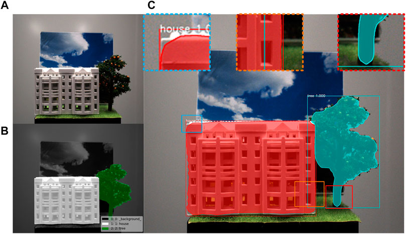
FIGURE 5. (A) An real scene image and (B) its masked label files (C) Details display after instance segmentation.
The virtual scene was rendered with 3D studio Max software, and its sampling was adopted to be consistent with the real scene sampling settings. In addition, the “Z depth” channel was rendered to obtain the “car” model’s depth maps, where the front end of the car was 14.3 cm from the camera. The gray value of the depth map of the car area was between 139 and 232 (0–255 is used to represent the gray range of each gray image). Figures 6A,B show one of the sampled images and its depth map of the virtual scene.
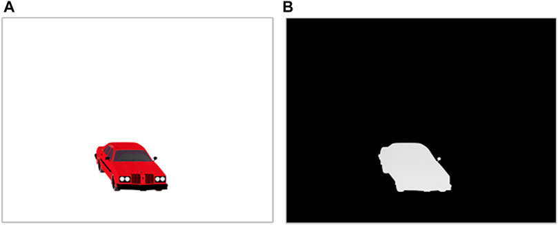
FIGURE 6. (A) A virtual scene image and (B) its depth map.
The trained model was used to predict all the real scene images to be encoded, and the corresponding images with masks were obtained. Digital image processing technology is used to assign pseudo-depth-values to the areas covered by each mask in each image. In order to ensure that the car stopped between the house and the tree, we assigned values to two groups of pseudo-depth-maps. In one group, the house was 100, the tree was 255, and the background was 0. In the other group, the house was 255, the tree was 100, and the background was 0 (corresponding to the principle). Figure 7 shows three pseudo-depth-maps.
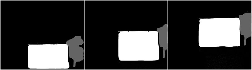
FIGURE 7. Three gray images with pseudo-depth-values.
Figure 8 shows some encoded perspectives, which are the images with the correct occlusion relationship selected from the results of the above-mentioned two groups of pseudo-depths. The number labels in the upper right-hand corner of the perspectives represent the ranking of these images in the sequence. We zoomed-in on some of the details of the first three images to show the coding effect. It can be seen that the information of the virtual scene has been integrated into the house and tree of the real scene. In perspective (28,29), the rear part of the car is blocked by the house, and the tree is blocked by the front of the car. In perspective (35,29), there is no occlusion relationship between the car and the house. In perspective (42,29), the house is blocked by the front of the car. This further proves the effectiveness of the proposed method for the fusion of real and virtual occlusion. In addition, our optical field coding method only determines the position at which there is scene information in the virtual images and directly retains the real scene information of the position at which there is no scene information. Therefore, the encoded images are not affected by the incomplete coverage of the instance segmentation mask.
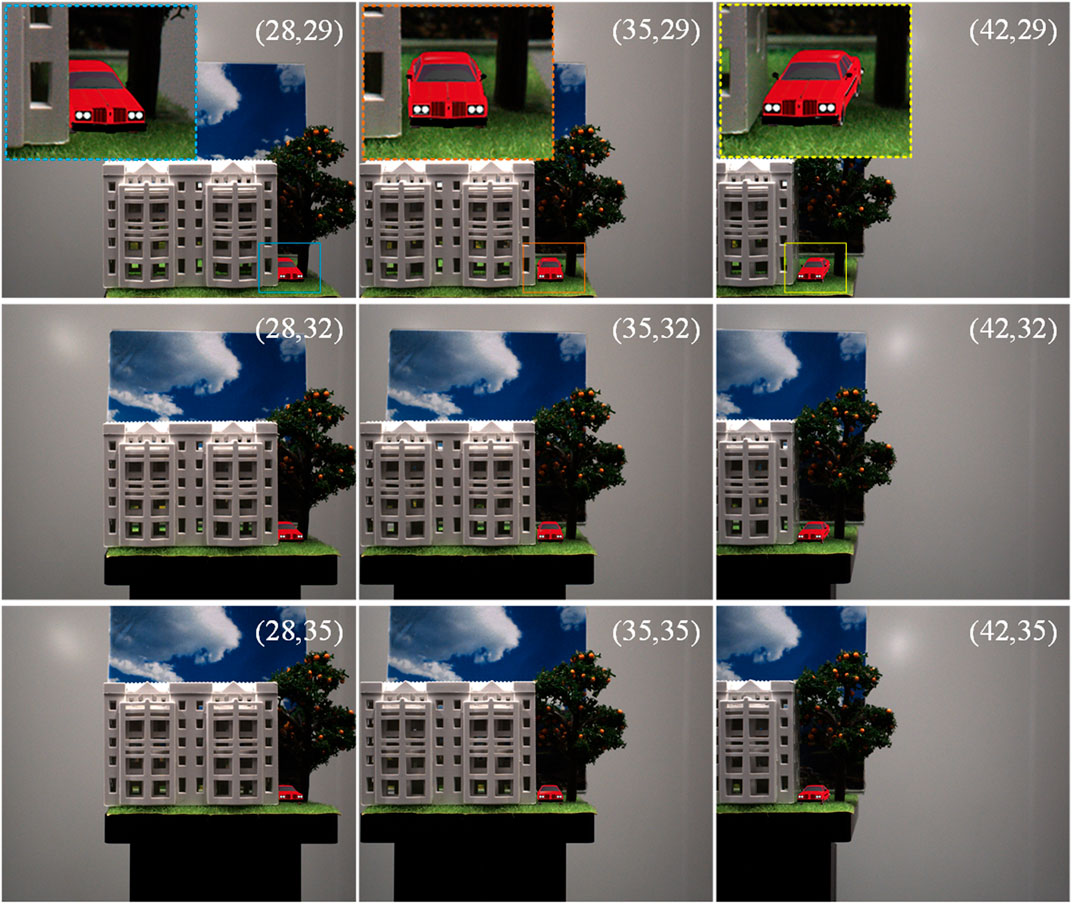
FIGURE 8. Nine encoded perspectives.
After the fusion perspectives of real and virtual scenes are obtained, the EPISM method can be used for the image process to generate the optical field information that can be directly used for holographic printing. For details of the EPISM printing method, please refer to Ref. [25].
The EPISM holographic stereogram printing method proposed by our group is used for image pre-processing to obtain the exposure images for holographic printing. The optical experimental scheme was set up as shown in Figure 9. A 400-MW/639-nm single longitudinal mode linearly polarized solid-state laser (CNI MSL-FN-639) was used as the light source, and an electronic shutter (Sigma Koki SSH-C2B) was used to control the exposure time. After passing through a
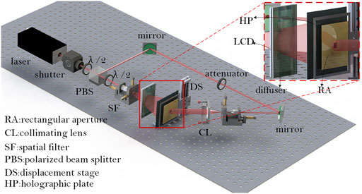
FIGURE 9. Holographic printing optical scheme.
After printing, the holographic plate can reconstruct 3D images in the conjugate of original reference light after developing and bleaching. As shown in Figure 10, the reconstructed image was taken with a Canon camera and a macro lens with a focal length of 100 mm, which was placed approximately 40 cm in front of the holographic plate.
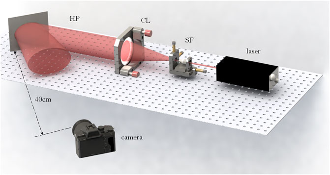
FIGURE 10. Holographic optical reconstruction scheme.
As shown in Figure 11, the full parallax reconstruction effect of an AR 3D image in a holographic stereogram at different angles of view can be observed. It can be further observed that the fusion reconstruction images of real and virtual scenes are not only consistent with the original scene at the time of acquisition but the occlusion of a virtual scene to a real scene also conforms to the corresponding spatial position relationship, that is, at the left angle (−5°, +2.5°), the car is blocked by the house, and at the right angle (+5°, +2.5°), the house is blocked by the car, which shows the correctness of the optical field coding method. The holographic stereogram has smooth motion parallax and no visual jump effect. According to the printing principle of the EPISM method, the field of view of the holographic stereogram is determined by the field of view of the printing system and each hogel. In this experiment, the field of view is 39.8°. However, due to the large main part of the real scene, when the observer is located in the limited visual area ±19.9°, the foreground part of the entire real scene (houses, cars, and trees in the image) will not be observed in the reconstructed optical field. In order to capture the complete reproduction image of the real scene and to better display the AR 3D display effect, the shooting angle of the digital camera—that is, the horizontal and vertical viewing angles shown in Figure 11—is less than 19.9°. The horizontal observation angle is also slightly larger than the vertical observation angle.
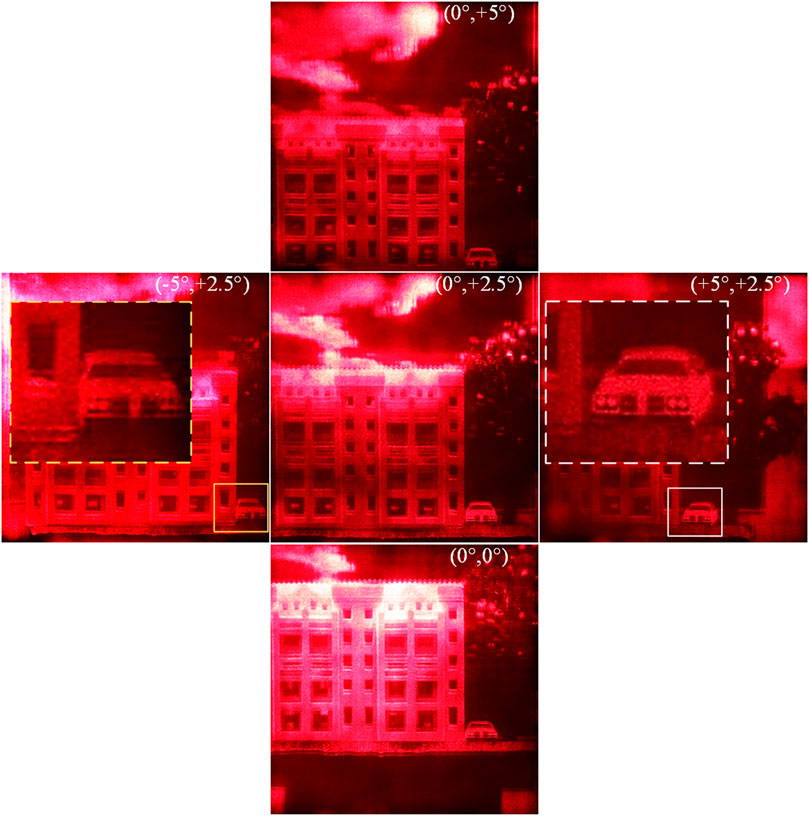
FIGURE 11. Reproduction images of five viewpoints.
In order to further test the ability of detail expression (see Figure 12) and the expressiveness of the scene depth (see Figure 13) of the AR hologram obtained by the proposed method, we used the same printing system and selected a soldier model and a “BAM!” model as the real scene and the virtual scene, respectively; the holographic stereogram was printed again, and the reconstructed image was taken.
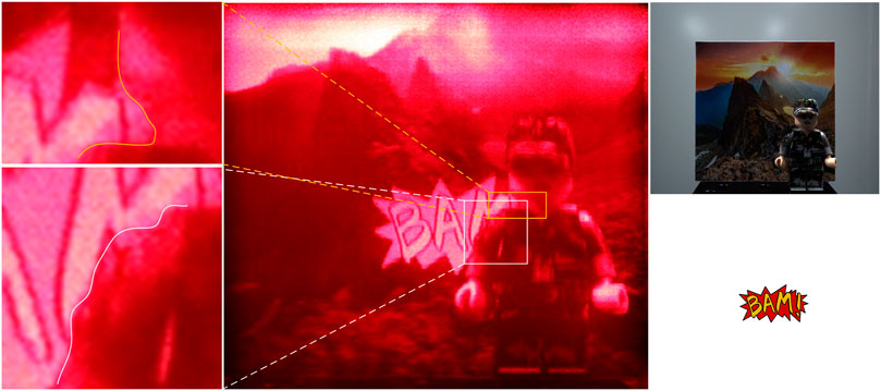
FIGURE 12. Effect display of a new scene of augmented-reality display.
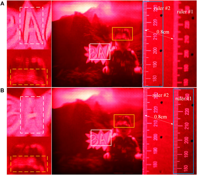
FIGURE 13. Analysis of scene depth information.
Figure 12 shows the sampled image and the reproduced image, which is successfully displayed by the fusion of real and virtual scenes and some details (from right to left). In the two detailed images on the left, the neck of the soldier can be well integrated with the virtual scene, but the arm is not as smooth as in the sampled image, which is due to the difference of coverage of different parts in the segmentation results of the instance. This shows that the proposed optical field coding method of a holographic stereogram AR display is greatly affected by the effect of instance segmentation. Therefore, in order to achieve high-quality display, the accuracy of instance segmentation must be improved.
Two rulers were placed to help display the comparison results, as shown in Figure 13. The distance between ruler #1 and the holographic plate is 14.3 cm and that between ruler #2 and the holographic plate is 13.5 cm, which are consistent with the sampling parameters. It can be seen that when the camera focuses on ruler #2, the letter “A” is displayed clearly. When ruler #1 is clear, the soldier is clearer than ruler #2. This not only means that there is a depth difference between the real and virtual scenes in the reconstructed image but also indicates that the depth difference does not change with the pseudo-depth assignment. It should be pointed out that the real camera sampling effect is not as good as that of the virtual camera in the software; the contrast effect is not obvious, but we can see that the artifact of the hat is reduced.
In our work, a fusion coding method of 3D real and virtual scenes information is proposed to achieve an AR-based holographic stereogram. Theoretical analysis and experimental results show that the proposed coding method can effectively add some virtual 3D elements into the real scene to enhance the visual experience in the field of holographic stereogram 3D display. The combination of real and virtual scenes fully considers the occlusion relationship, which is not a simple scene superposition. The core is to assign and determine the pseudo-depth after instance segmentation. There is still a large gap between the AR 3D display mentioned in this paper and the latest work in the field of AR, but the proposed method provides a basic idea for the research direction of holographic stereogram AR 3D display, which can be further explored. For example, by continuously improving the efficiency of instance segmentation, the scenes can be more accurately foreground-extracted. Moreover, if the accurate depth calculation method can be studied, then using the accurate depth value as the basic processing data can better present the effect of holographic stereogram AR 3D display. It should be pointed out that our work only discusses simple and small scenes that tend to be the ideal conditions. However, the related work of complex scenes still needs further analysis and research; for example, there are no obvious foreground objects and background objects in the scene, or the front and back objects belong to the same instance. Taking our experiment as an example, if the car is located inside of the garage, only a part of the garage needs to be separated in the instance segmentation, which violates the original intention of the instance segmentation algorithm. Therefore, the methods mentioned in this paper have some limitations. Therefore, the aforementioned related issues must be further studied in future.
The datasets presented in this study can be found in online repositories. The names of the repository/repositories and accession number(s) can be found below: https://github.com/yanyu-holo/Augmented-Reality-Based-Holographic-stereogram.
Conceptualization, YL, ML and XY; methodology, YL, SC and XY; software, XW, ML and TJ; validation, PL, XJ and XW; formal analysis, YL and TJ; resources, XY and SC; data curation, XL; writing—original draft preparation, YL, XL and ML; writing—review and editing, YL and ML; visualization, SC; supervision, XY; project administration, XY; funding acquisition, XY All authors have read and agreed to the published version of the manuscript.
The National Key Research and Development Program of China (2017YFB1104500); National Natural Science Foundation of China (61775240); Foundation for the Author of National Excellent Doctoral Dissertation of the People’s Republic of China (201432).
The authors declare that the research was conducted in the absence of any commercial or financial relationships that could be construed as a potential conflict of interest.
All claims expressed in this article are solely those of the authors and do not necessarily represent those of their affiliated organizations, or those of the publisher, the editors and the reviewers. Any product that may be evaluated in this article, or claim that may be made by its manufacturer, is not guaranteed or endorsed by the publisher.
We thank LetPub (www.letpub.com) for its linguistic assistance during the preparation of this manuscript.
1. Brotherton-Ratcliffe D. Ultra-realistic Imaging: Advanced Techniques in Analogue and Digital Colour Holography,Hans Bjelkhagen and David Brotherton-Ratcliffe. Boca Raton, FL: Ultra-Realistic Imaging - Advanced Techniques in Analogue and Digital Colour Holography (2013).
2. Su J, Yan X, Huang Y, Jiang X, Chen Y, Zhang T. Progress in the Synthetic Holographic Stereogram Printing Technique. Appl ences (2018) 8(6):851. doi:10.3390/app8060851
3. Yamaguchi M. Light-Field and Holographic Three-Dimensional Displays [Invited]. J Opt Soc Am A (2016) 33(12):2348. doi:10.1364/josaa.33.002348
5. Qian N. Binocular Disparity and the Perception of Depth. Neuron (1997) 18(3):359–68. doi:10.1016/s0896-6273(00)81238-6
6. Wang Z, Lv G, Feng Q, Wang A, Ming H. Enhanced Resolution of Holographic Stereograms by Moving or Diffusing a Virtual Pinhole Array. Opt Express (2020) 28(15):22755–66. doi:10.1364/OE.396639
7. Wang Z, Lv GQ, Feng QB, Wang AT, Ming H. Resolution Priority Holographic Stereogram Based on Integral Imaging With Enhanced Depth Range. Opt Express (2019) 27(3):2689–702. doi:10.1364/OE.27.002689
8. Li Q, He W, Deng H, Zhong F-Y, Chen Y. High-Performance Reflection-Type Augmented Reality 3D Display Using a Reflective Polarizer. Opt Express (2021) 29(6):9446. doi:10.1364/oe.421879
9. Shi L, Li B, Kim C, Kellnhofer P, Matusik W. Towards Real-Time Photorealistic 3D Holography With Deep Neural Networks. Nature (2021) 591(7849):234–9. doi:10.1038/s41586-020-03152-0
10. Maimone A, Georgiou A, Kollin JS. Holographic Near-Eye Displays for Virtual and Augmented Reality. ACM Trans Graph (2017) 36(4):1–16. doi:10.1145/3072959.3073624
11. Yang X, Zhang H, Wang Q-H. A Fast Computer-Generated Holographic Method for VR and AR Near-Eye 3D Display. Appl Sci (2019) 9(19):4164. doi:10.3390/app9194164
12. Starner T. Project Glass: An Extension of the Self. IEEE Pervasive Comput (2013) 12(2):14–6. doi:10.1109/mprv.2013.35
14. Breen D, Whitaker RT, Rose E, Tuceryan M. Interactive Occlusion and Automatic Object Placement for Augmented Reality. Computer Graphics Forum (1996) 15:11. doi:10.1111/1467-8659.1530011
15. Ong KC, Teh HC, Tan TS. Resolving Occlusion in Image Sequence Made Easy. Vis Computer (1998) 14(4):153–65. doi:10.1007/s003710050131
16. Newcombe RA, Izadi S, Hilliges O, Molyneaux D, Fitzgibbon AW. KinectFusion: Real-Time Dense Surface Mapping and Tracking. In: IEEE International Symposium on Mixed & Augmented Reality (2012).
17. Wloka MM. Resolving Occlusion in Agumented Reality. In: Proceedings of the 1995 symposium on Interactive 3D graphics (1995) 5–12.
18. Fischer J, Huhle B, Schilling A. Using Time-Of-Flight Range Data for Occlusion Handling in Augmented Reality. In: Proceedings of the 13th Eurographics conference on Virtual Environments (2007). p. 109–16.
19. Berger MO. Resolving Occlusion in Augmented Reality: a Contour Based Approach without 3D Reconstruction. Proc IEEE Computer Soc Conf Computer Vis Pattern Recognition (2002) 91–96. doi:10.1109/CVPR.1997.609304
20. Wang HL, Sengupta K, Kumar P, Sharma R. Occlusion Handling in Augmented Reality Using Background-ForeGround Segmentation and Projective Geometry. Presence: Teleoperators & Virtual Environments (2005) 14(3):264–77. doi:10.1162/105474605323384636
21. Wang HL, Sengupta K, Sharma R. Augmented Reality with Occlusion Rendering Using Background-ForeGround Segmentation and Trifocal Tensors. In: International Conference on Multimedia & Expo (2003).
22. Setohara H, Kato H, Kawamoto K, Tachibana K. A Simple Solution of Occlusion Problem in Augmented Reality and its Application for Interaction. Trans Virtual Reality Soc Jpn (2004) 9:387–95. doi:10.18974/tvrsj.9.4_387
23. Roxas M, Hori T, Fukiage T, Okamoto Y, Oishi T. Occlusion Handling Using Semantic Segmentation and Visibility-Based Rendering for Mixed Reality. In: Proceedings of the 24th ACM Symposium on Virtual Reality Software and Technology (2018).
24. He K, Gkioxari G, Dollár P, Girshick R. Mask R-CNN. IEEE (2017) 2980–2988. doi:10.1109/ICCV.2017.322
25. Jian S, Quan Y, Huang Y, Jiang X, Yan X. Method of Single-step Full Parallax Synthetic Holographic Stereogram Printing Based on Effective Perspective Images' Segmentation and Mosaicking. Opt Express (2017) 25(19):23523–44. doi:10.1364/OE.25.023523
26. Su J, Yan X, Jiang X, Huang Y, Chen Y, Zhang T. Characteristic and Optimization of the Effective Perspective Images' Segmentation and Mosaicking (EPISM) Based Holographic Stereogram: an Optical Transfer Function Approach. Sci Rep (2018) 8(1):4488. doi:10.1038/s41598-018-22762-3
27. Roy A, Todorovic S. Monocular Depth Estimation Using Neural Regression Forest. In: 2016 IEEE Conference on Computer Vision and Pattern Recognition. (Seattle, WA: CVPR) (2016).
28. Fu H, Gong M, Wang C, Tao D. A Compromise Principle in Deep Monocular Depth Estimation. arXiv preprint arXiv:170808267. (2017).
29. Yan H, Zhang S, Zhang Y, Zhang L. Monocular Depth Estimation with Guidance of Surface normal Map. Neurocomputing (2017) 280(MAR.6):86–100. doi:10.1016/j.neucom.2017.08.074
30. Isard M, Blake A. CONDENSATION—Conditional Density Propagation for Visual Tracking. Int J Computer Vis (1998) 29(1):5–28. doi:10.1023/a:1008078328650
31. Sekine Y. Effects of Country-Of-Origin Information on Product Evaluation: An Information Processing Perspective. Neurosci Biobehavioral Rev (2017) 72(6):232. doi:10.1016/j.neubiorev.2016.12.003
32. Chang JR, Chen YS. Pyramid Stereo Matching Network. In: 2018 IEEE/CVF Conference on Computer Vision and Pattern Recognition. (Salt Lake City, UT: CVPR) (2018).
33. Liu F, Shen C, Lin G, Reid I. Learning Depth from Single Monocular Images Using Deep Convolutional Neural Fields. IEEE Trans Pattern Anal Mach Intell (2015) 38(10):2024–39. doi:10.1109/TPAMI.2015.2505283
34. Schwarz M, Schulz H, Behnke S. RGB-D Object Recognition and Pose Estimation Based on Pre-Trained Convolutional Neural Network Features. In: IEEE International Conference on Robotics & Automation (2015).
35. Zhan H, Garg R, Weerasekera CS, Li K, Agarwal H, Reid I. Unsupervised Learning of Monocular Depth Estimation and Visual Odometry with Deep Feature Reconstruction. Salt Lake City, UT: IEEE (2018).
36. Hc A, Xq A, Ly A, Qd A, Jq B, Pah A. DCAN: Deep Contour-Aware Networks for Object Instance Segmentation from Histology Images - ScienceDirect. Med Image Anal (2017) 36:135–46. doi:10.1016/j.media.2016.11.004
37. Xu Y, Li Y, Liu M, Wang Y, Lai M, Chang IC. Gland Instance Segmentation by Deep Multichannel Side Supervision. IEEE Trans Biomed Eng (2016) 99:1. doi:10.1007/978-3-319-46723-8_57
Keywords: holographic stereogram, augmented reality, instance segmentation, 3D display, fusion of 3D real and virtual scenes
Citation: Liu Y, Yan X, Liu X, Wang X, Jing T, Lin M, Chen S, Li P and Jiang X (2021) Fusion Coding of 3D Real and Virtual Scenes Information for Augmented Reality-Based Holographic Stereogram. Front. Phys. 9:736268. doi: 10.3389/fphy.2021.736268
Received: 05 July 2021; Accepted: 05 August 2021;
Published: 24 August 2021.
Edited by:
Liangcai Cao, Tsinghua University, ChinaReviewed by:
Zi Wang, University of Delaware, United StatesCopyright © 2021 Liu, Yan, Liu, Wang, Jing, Lin, Chen, Li and Jiang. This is an open-access article distributed under the terms of the Creative Commons Attribution License (CC BY). The use, distribution or reproduction in other forums is permitted, provided the original author(s) and the copyright owner(s) are credited and that the original publication in this journal is cited, in accordance with accepted academic practice. No use, distribution or reproduction is permitted which does not comply with these terms.
*Correspondence: Xingpeng Yan, eWFueHAwMkBnbWFpbC5jb20=
†These authors have contributed equally to this work
Disclaimer: All claims expressed in this article are solely those of the authors and do not necessarily represent those of their affiliated organizations, or those of the publisher, the editors and the reviewers. Any product that may be evaluated in this article or claim that may be made by its manufacturer is not guaranteed or endorsed by the publisher.
Research integrity at Frontiers
Learn more about the work of our research integrity team to safeguard the quality of each article we publish.