- 1Department of Optical Quantum Electronics, Institute of Physics of the NAS of Ukraine, Kyiv, Ukraine
We report on the effects associated with photonic nanojet (PNJ) formation under illumination of a metallic spherical particle with a focused light beam with polarization singularity. Owing to radial polarization, the strongly focused beam generates the on-axis localized structure of intensity in the shadow area of the metal scatterer of different sizes, from the Rayleigh particle to microbeads. Significant amplification factor, small transverse size, and zero magnetic component on the axis and longitudinal polarization of the electric field are the distinctive features of such structures.
1 Introduction
Normally focusing a light wave with a system of lenses cannot achieve the light spot in focus less than a half of the wavelength [1]. This classical conclusion is obtained taking into account the fact that the wave freely propagates from the lens surface to the focal plane and the distance between them is much larger than the wavelength. The current problems in microscopy, nanostructuring, and nanolithography require various approaches to enter under the diffraction limit. For example, multiphoton absorption of an illuminated sample is widely used [1, 2]. Another way is to obtain a localization of the electromagnetic field in the near zone of the scatterer. If its size is of the same order as the wavelength, field structures compressed in one or several directions can appear in the shadow area. The structures with the transverse dimensions less than the wavelength and the elongation greater than the wavelength are called photonic nanojets (PNJ) [3, 4]. Photonic nanojets attract a continuously growing interest as a potential tool for operation with concentrated light forms under the diffraction limitation. Most of the studies in this area are directed to the formation of PNJ by light diffraction on dielectric microspheres [2–14] and on microcylinders [15–17]. There are also studies devoted to other forms of scatterers, for example, microaxicons [18] or microdisks [19]. In most of the studies, the scatterers of non-absorbing homogeneous isotropic dielectric materials are considered [5–7, 11–13]. However, there are also studies devoted to diffraction on dielectric scatterers with an inhomogeneous refractive index [20–22] and dielectric particles coated with metal [17, 23]. In our best knowledge, the formation a nanojet by light scattering on full-metal micro particles has been not considered yet, except our brief remark about possibility of PNJ formation using strongly focused singular beams [24]. In this study, we pay attention to the case of a metallic spherical particles illuminated by a singular optical beam, i.e., carrying optical singularity in a form of an optical vortex with a helical phase front or radial or azimuthal polarization with undetermined state on the beam axis.
2 Lorenz–Mie Theory and Computation Approaches
In this section, we introduce all necessary notations and briefly describe computational approaches. Previously we already described most of them in our studies [24–26].
2.1 Lorenz–Mie Theory
We consider the scattering by an isotropic homogeneous spherical particle of radius Rp, dielectric constant ϵp, and magnetic permeability μp. The particle is embedded in a uniform isotropic dielectric medium with dielectric constant ϵmed and magnetic permeability μmed. The center of the spherical particle is located at the origin. We denote electric and magnetic field components of a harmonic electromagnetic wave inside the particle as
The incident wave is an external wave which freely propagates in the medium in the absence of any scatterer. The scattered wave in the far field is a completely outgoing wave. The fields inside and outside the particle can be considered as a sum of the series of the vector spherical wave functions (VSWF).
where
where
where
where θ and ϕ are polar and azimuthal angles of the spherical coordinate system, and
Now the incident wave is characterized by amplitudes
where
where n = np/nmed, μ = μp/μmed, x = Rpkmed,
2.2 Far-Field Matching
The formulas (12–16) are useful only if the expansion for the incident light beam is known. In this section, we describe the approach which allows finding them with this condition.
In the far-field, any beam can be described as a superposition of incoming and outgoing waves:
where the notation, we defined previously as ρmed we redefine here as ρ = kmedr and
where
Alternatively, the far-field distribution of the incident light beam (
where
Therefore,
Taking into account that a set of the vector spherical harmonics is orthonormal,
the coefficients of the expansion for the incident light beam can be found in the following form:
Exactly these equations are used to calculate the coefficients of the beam expansion.
2.3 Nonparaxial Laguerre–Gaussian Beams
To describe the nonparaxial Laguerre–Gaussian (LG) beams, we use the same expressions for the far-field angular distribution as in ref. [35].
where f is the focusing parameter (the bigger the f, the smaller the waist size of the beam, and if f ≪ 1, the waist size equals to
where
Equation 28 describes the x-polarized LG beam; similarly, it is possible to define y-polarized LG beam and circular polarized beams:
Let us consider LG beams with an azimuthal index m = ±1, which describes optical vortices with a unity topological charge. For the x and y-polarized beams, the electric far fields are described by
In the Hilbert space of all superpositions of such modes (with fixed f and n), it is possible to select another orthogonal basis:
Previously, we gave some analysis of beam shape coefficients (Eqs 26, 27) of the x-polarized LG beams [24, 25]. Here, we discuss the expansion of radial and azimuthal polarized beam and the LG modes with unity topological charge and with circular polarization, which have the same sign of the spin and orbital angular momentum (
For translation along the z-axis beams, the shape coefficients can be written in the same form (zero coefficients remain zero). Among all nonzero components of VSWF series of the considered modes, only
3 Results and Discussion
In this section, we present the results of numerical computations and make a comparison between plasmonic nanojet formation and the nanojets formed by dielectric spheres. Also, we discuss some specific properties of the plasmonic nanojets.
Formation of photonic nanojets for spherical dielectric particles illuminated by a plane wave is a well known problem [3, 4]. The plane wave can be surrogated by a Gaussian beam with n = 0, m = 0, and a sufficiently small focusing parameter f (see Eq. 32). This limiting case is illustrated in Figure 1, which shows the intensity distributions for the total light wave field in the x-z and the y-z planes. The incident wave is the x-polarized LG beam with n = 0, m = 0, and f = 0.05.
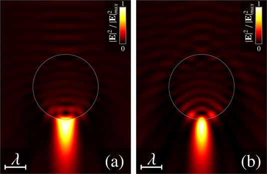
FIGURE 1. Near-field intensity distributions in (A) the x-z plane and (B) the y-z plane. Incident wave is the non-vortex Gaussian beam (LG0,0). Parameters are: f = 0.02, Rp = 1.5λ, nr = 1.3.
The radius of the spherical particle is Rp = 1.5λ (λ is the wavelength in the surrounding medium) and the relative refractive index is nr = np/nmed = 1.3. The field distributions of the scattered wave are characterized by the presence of extended along the z axis focusing zone, formed in the shadow area of the microbead. The transverse size (width) of this zone is less than the wavelength of incident light, whereas its size along the z-axis (length) is relatively large. Such a jet-like light structure is called photonic nanojet [3, 4]. The shape and dimensions of the nanojet are varying with an increase of the focusing parameter f.
In Figure 2, several examples of nanojets generated by scattering LG modes with different focusing parameters are illustrated. It can be seen that increasing of the focusing strength f leads to the reduction of the length of the nanojet. At some value of the parameter f, the shape is not jet-like and the size is smaller than a wavelength in all three dimensions. The light structure, the size of which is less than a wavelength and which has relatively high intensity, is called a hot spot. For strongly focused beam, the point of the highest intensity is located inside the scatterer. Such a behavior can be explained in geometric optic limit: the microbead can be considered as a microlens; therefore, the stronger focused beam should be focused closer to the origin.
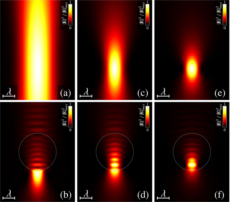
FIGURE 2. Diffraction on the dielectric spherical particle: near-field intensity distributions in the x-z plane (B, D, F) and freely propagating wave (A, C, E). The incident wave is a non-vortex Gaussian beam (LG0,0). zb = 1.5λ, Rp = 1.5λ, and nr = 1.3. (A, B)—f = 0.1, (C, D)—f = 0.2, and (E, F)—f = 0.3.
The characteristics of the scattered light are known to strongly depend on a number of other factors. For example, the particle absorption coefficient, the relative refractive index of the particle nr = np/nmed, the position of the center of the beam Rb, and the scatterer size Rp. Starting from some value, the reduction of the scatterer size leads to the instability of the nanojet. A nanojet is spitted into two hot spots, located on the opposite sides of the sphere along the x-axis. The splitting is illustrated on the Figure 3. Such a behavior can be explained considering the Rayleigh particle in the plane wave (close to the Rayleigh particle is illustrated in the Figure 3C). The direction of polarization inside the particle is approximately the same and polarization has the same direction as polarized incident way (x-polarized). Due to the boundary conditions on the surface, the highest intensity near the particle is on the opposite sides of the sphere along the x-axis. That explains two symmetrical hot spots illustrated in Figure 3C.
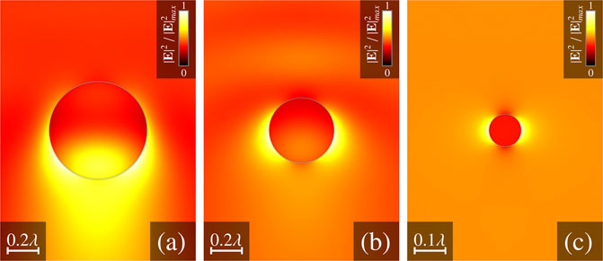
FIGURE 3. Diffraction on the dielectric spherical particle: near-field intensity distributions in the x-z plane. The incident wave is a vortex-free Gaussian beam (LG0,0). f = 0.02 and nr = 1.3. (A)—Rp = 0.3λ, (B)—Rp = 0.2λ, and (C)—Rp = 0.05λ.
Unlike dielectric particles, the full-metal microbeads do not allow to generate nanojets by scattering a plane electromagnetic wave (or focused LG beam with n = 0 and m = 0) on them. The scattering of the near-plane wave on the metal sphere is illustrated in Figure 4.
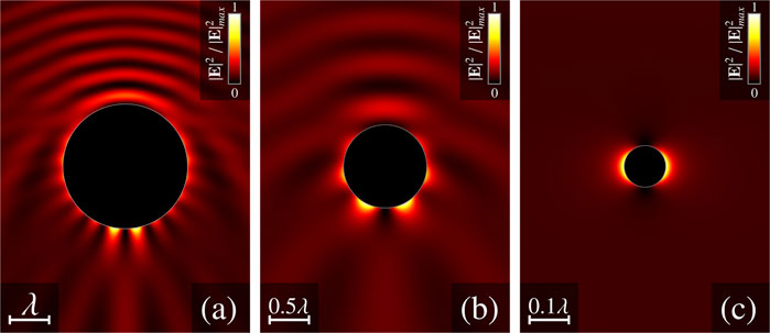
FIGURE 4. Diffraction on the metal spherical particle: near-field intensity distributions in the x-z plane. The incident wave is a non-vortex Gaussian beam (LG0,0). f = 0.02λ and ϵp/ϵmed = −22.5 + 1.4i. (A)—Rp = 1.5, (B)—Rp = 0.5, and (C)—Rp = 0.05.
In the case of metal scatterer with a size smaller than the wavelength the impossibility of nanojet or on the z-axis hot spot generation can be explained in the same way as for dielectric particles. In the case of scatterer size Rp amounting several wavelengths, metal particle is opaque for a light, and unlike the dielectric particle, it cannot be considered as a microlens. In the shadow area of the scatterer, the light can propagate only on a surface in a thin skin layer. In case the scatterer is large, the surface can be considered locally as a plane, each point of which is illuminated by a superposition of the p-polarized and s-polarized waves. The p-polarized wave generates TM polarized surface plasmon polariton on the illuminated side of the sphere, which propagates to the shadow side of the particle. Due to the symmetry of the incident field, such plasmon polaritons interfere destructively on the z-axis. Concerning s-polarized waves, they do not have much influence on the intensity directly near the particle surface due to the boundary conditions; furthermore, the TE polarized surface plasmon polariton is prohibited on the plane surface [37].
Previously, we reported about possibility of the nanojet generation by a scattering of the LG beams with an azimuthal index m = ±1 [24] and impossibility of nanojet generation on the z-axis in case
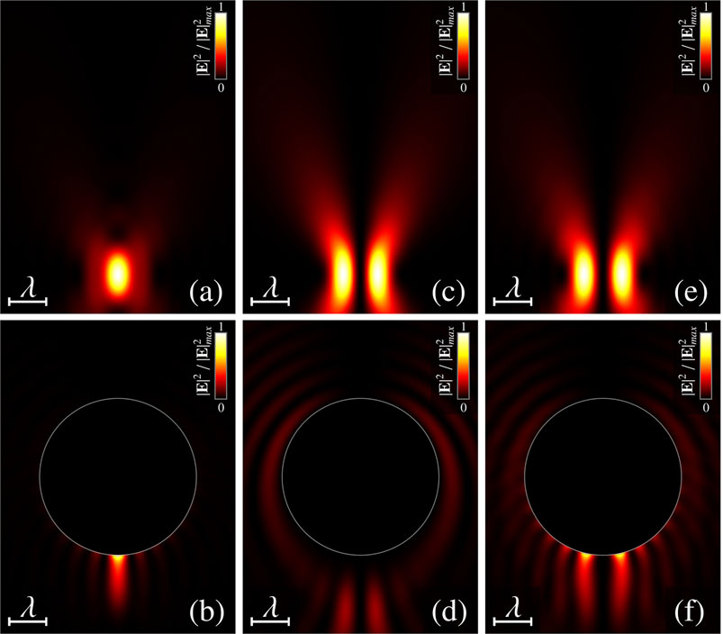
FIGURE 5. Diffraction on the metal spherical particle: near-field intensity distributions in the x-z plane (B, D, F). Freely propagating wave (A, C, E). zb = 1.5λ, Rp = 2λ, ϵp/ϵmed = −22.5 + 1.4i, and f = 0.3 (A, B)—LG0,rad beam, (C, D)—LG0,az beam, and (E, F)—
It can been seen that the on the z-axis, nanojet is formed only in case of radial polarized wave, whereas the azimuthal polarized beam and optical vortex with spin angular momentum (
Unlike the nanojets, which are generated by a scattering the plane wave or vortex-free Gaussian beam, the plasmonic nanojets do not split into two off-axis hot spots if the size of the scatterer is small. Instead, reducing the size of the scatterer leads to the reduction in the length and width of the nanojet, providing the evolution of the nanojet into the hot spot. In Figure 6, several sizes of metal spheres are illustrated, which are illuminated by the radial polarized mode. The nature of the two hot spot formation (Figure 6C) is the same as on Figure 4C. The location of them is different due to the z-polarized electric field on the z-axis.
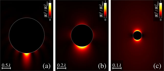
FIGURE 6. Diffraction on the metal spherical particle: near-field intensity distributions in the x-z plane. The incident wave a radial polarized Gaussian beam (LG0,rad). ϵp/ϵmed = −22.5 + 1.4i, f = 0.3 , Rp = 1.5λ, and nr = 1.3. (A)—Rp = 1λ, zb = 1.5λ, (B)—Rp = 0.25λ, zb = 0, and (C)—Rp = 0.05λ, zb = 0.
In the Figure 7, the dependence of the length and width of the nanojet/hot spot on a particle size is illustrated. The width and length are calculated in the following way. The first step is to find the point of the maximum intensity outside the sphere on the z-axis. It is considered as a center of the hot spot/nanojet. After that, the width is found as a FWHM (full width at half maximum) along the x-axis relative to the center. The length is find as length of the section, the intensity on which is reduced by e times along the z-axis (not including the scatterer). The relative permittivity of the particle is ϵp/ϵmed = −22.5 + 1.4i, which has gold at wavelength 780 nm. It can be seen that for Rp ≥ 2.6λ, the length of the nanojet is bigger than the wavelength and continue increases up to the Rp = 3 (large sizes are not presented). The width in this section is less than λ/3. Approximately at Rp = 1.5, the width and the length of the hot area are equal, and the reduction of the particle size leads to the hot spot localization. Note that the length decreases faster than the width of the hot spot. Such localization can be an effect of the needle [38].
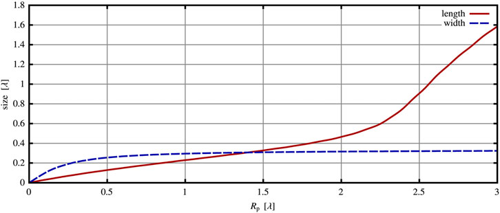
FIGURE 7. Dependence of the length and width of the plasmonic nanojet/hot spot on a particle size. The incident wave is a radial Gaussian beam (LG0,rad). ϵp/ϵmed = −22.5 + 1.4i, f = 0.3, and zb = 0.75Rp.
The intensity of such nanojets and hot spots can be higher than the intensity of the original beam. It depends on a number of factors, such as particle size, permittivity, focusing factor f, and position of beam focusing. In Figure 8, the dependence of the amplification factor of the plasmonic nanojet on a particle size is illustrated. All calculations are done for the focusing factor f = 0.3, relative permittivity of the particle as gold on 780 nm, and the distance between the center of the sphere and center of the beam equals zb = 0.75Rp. The amplification factor is calculated as a ratio of maximal intensity of nanojet/hot spot to maximal intensity of the incident beam. It can be seen that at the approximate size of the sphere Rp ≈ λ/4, there is a high maximum. The amplification factor at this point reaches 25. There are also some expressionless peaks at the bigger particle size, but the total tendency is a reduction of the amplification factor after the Rp ≈ λ/4.
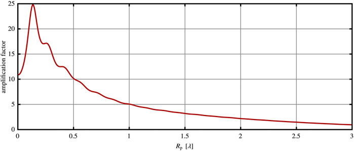
FIGURE 8. Dependence of amplification factor of the plasmonic nanojet/hot spot on a particle size. The incident wave is a radial Gaussian beam (LG0,rad). ϵp/ϵmed = −22.5 + 1.4i, f = 0.3, and zb = 0.75Rp.
4 Conclusion
The main object of research in this study is a determination of the conditions for photonic nanojets and hot spots formation with inspection of their properties. In this goal, we have used the Lorenz–Mie theory to analyze the light scattering problem for isotropic spherical metal scatterers illuminated with radial, azimuthal, and circular polarized LG beams. To describe such beams, we apply far-field angular distribution Eq. 32. Then, we use in our derivations the far-field matching approach to find the beam shape coefficients (Eqs 26, 27). The required nanojet can be generated using the superposition of LG beams with a unity topological charge, as we noted previously [24], and in this report, we made a more accurate and deep analysis. We have shown that any such a superposition can be considered as a sum of the radial, azimuthal, and circular polarized Laguerre–Gaussian modes, with the same sign of spin and orbital angular momentum. The possibility of the nanojet or hot spot generation along the z-axis is determined by the contribution of the radial mode, whereas the diffraction of the azimuth or circular polarized LG beams gives zero electric field on the z-axis. The nanojets or hot spots located on the z-axis, which are generated using radial polarized modes, have zero magnetic field component, and the electric field is z-polarized.
In our calculations, we use a relation of dielectric permittivity of the particles and a medium ϵp/ϵmed = −22.5 + 1.4i, which is close to one for the gold in the vacuum at wavelength 780 nm. Concerning the sizes of the longitudinal nanojets, the width of them does not exceed λ/3 (for particle size Rp < 6λ). Decreasing the particle size leads to decreasing the nanojet sizes in all three dimensions, but the length decreases faster than the width. Gradually, nanojet evolves into one on the z-axis hot spot, unlike the classical nanojet, which splits into two non-axis hot spots. The maximum intensity amplification factor reaches up to 25 (for our parameters of the beam and the scatterer, Rp ≈ λ/4). A significant amplification factor and the small transverse size make them perspective for microscopy, nanolithography, nanopatterning, and nanofabrication, and together with its longitudinal polarization, it can be interesting for on-surface second harmonic generation.
Data Availability Statement
The raw data supporting the conclusion of this article will be made available by the authors, without undue reservation.
Author Contributions
DP—theoretical analysis, calculations, preparation of the figures, working on a text, and discussion ideas. MV—working on a text, discussion ideas.
Funding
This research was conducted within the project “Photophysics of the processes of optical radiation interaction with photorefractive, solid-state, and bioorganic media” by National Academy of Sciences of Ukraine. DP was partially supported by a grant for research groups of young scientists from the National Academy of Science of Ukraine (Project No. 0120U100155).
Conflict of Interest
The authors declare that the research was conducted in the absence of any commercial or financial relationships that could be construed as a potential conflict of interest.
Publisher’s Note
All claims expressed in this article are solely those of the authors and do not necessarily represent those of their affiliated organizations, or those of the publisher, the editors, and the reviewers. Any product that may be evaluated in this article, or claim that may be made by its manufacturer, is not guaranteed or endorsed by the publisher.
References
1. Barry R. Masters. Confocal Microscopy And Multiphoton Excitation Microscopy: The Genesis Of Live Cell Imaging. Bellingham, Washington: SPIE (2006).
2. Shakhov A, Astafiev A, Plutenko D, Sarkisov O, Shushin A, Nadtochenko V. Femtosecond Optical Trap-Assisted Nanopatterning through Microspheres by a Single Ti:sapphire Oscillator. The J Phys Chem C (2015) 119:150507102628000.
3. Surdo S, Duocastella M, Diaspro A. Nanopatterning with Photonic Nanojets: Review and Perspectives in Biomedical Research. Micromachines (Basel) (2021) 12(3):2021. doi:10.3390/mi12030256
4. Darafsheh A. Photonic Nanojets and Their Applications. J Phys Photon (2021) 3(2):022001. doi:10.1088/2515-7647/abdb05
5. Luk’yanchuk BS, Yuan WZ, Lu Y. Laser Cleaning of Solid Surface: Optical Resonance and Near-Field Effects. In: CR Phipps, editor. High-Power Laser Ablation III, 4065. SPIE: International Society for Optics and Photonics (2000) p. 576–87.
6. Münzer H-J, Mosbacher M, Bertsch M, Zimmermann J, Leiderer P, Boneberg J. Local Field Enhancement Effects for Nanostructuring of Surfaces. J Microsc (2001) 202(1):129–35. doi:10.1046/j.1365-2818.2001.00876.x
7. Mosbacher M, Münzer H-J, Zimmermann J, Solis J, Boneberg J, Leiderer P. Optical Field Enhancement Effects in Laser-Assisted Particle Removal. Appl Phys A (2001) 72(1):41–4. doi:10.1007/s003390000715
8. Zheng YW, Luk’yanchuk BS, Lu YF, Song WD, Mai ZH. Dry Laser Cleaning of Particles from Solid Substrates: Experiments and Theory. J Appl Phys (2001) 90(5):2135–42. doi:10.1063/1.1389477
9. Leiderer P, Bartels C, König-Birk J, Mosbacher M, Boneberg J. Imaging Optical Near-fields of Nanostructures. Appl Phys Lett (2004) 85(22):5370–2. doi:10.1063/1.1819990
10. Huang SM, Hong MH, Luk’yanchuk BS, Zheng YW, Song WD, Lu YF, et al. Pulsed Laser-Assisted Surface Structuring with Optical Near-Field Enhanced Effects. J Appl Phys (2002) 92(5):2495–500. doi:10.1063/1.1501768
11. Li X, Chen Z, Taflove A, Backman V. Optical Analysis of Nanoparticles via Enhanced Backscattering Facilitated by 3-d Photonic Nanojets. Opt Express (2005) 13(2):526–33. doi:10.1364/opex.13.000526
12. Heifetz A, Kong SC, Sahakian AV, Taflove A, Backman V. Photonic Nanojets. J Comput Theor Nanosci (2009) 6(9):1979–92. doi:10.1166/jctn.2009.1254
13. Kong S-C, Sahakian AV, Heifetz A, Taflove A, Backman V. Robust Detection of Deeply Subwavelength Pits in Simulated Optical Data-Storage Disks Using Photonic Jets. Appl Phys Lett (2008) 92(21):211102. doi:10.1063/1.2936993
14. Lecler S, Haacke S, Lecong N, Crégut O, Rehspringer J-L, Hirlimann C. Photonic Jet Driven Non-linear Optics: Example of Two-Photon Fluorescence Enhancement by Dielectric Microspheres. Opt Express (2007) 15(8):4935–42. doi:10.1364/oe.15.004935
15. Itagi AV, Challener WA. Optics of Photonic Nanojets. J Opt Soc Am A (2005) 22(12):2847–58. doi:10.1364/josaa.22.002847
16. Liu C-Y. Ultra-high Transmission of Photonic Nanojet Induced Modes in Chains of Core-Shell Microcylinders. Phys Lett A (2012) 376(45):3261–6. doi:10.1016/j.physleta.2012.09.019
17. Liu C-Y. Superenhanced Photonic Nanojet by Core-Shell Microcylinders. Phys Lett A (2012) 376(23):1856–60. doi:10.1016/j.physleta.2012.04.035
18. Geints YE, Zemlyanov AA, Panina EK. Microaxicon-generated Photonic Nanojets. J Opt Soc Am B (2015) 32(8):1570–4. doi:10.1364/josab.32.001570
19. McCloskey D, Wang JJ, Donegan JF. Low Divergence Photonic Nanojets from Si_3N_4 Microdisks. Opt Express (2012) 20(1):128–40. doi:10.1364/oe.20.000128
20. Liu C-Y. Tunable Photonic Nanojet Achieved Using a Core-Shell Microcylinder with Nematic Liquid crystal. J Mod Opt (2013) 60(7):538–43. doi:10.1080/09500340.2013.796014
21. Mao X, Yang Y, Dai H, Luo D, Yao B, Yan S. Tunable Photonic Nanojet Formed by Generalized Luneburg Lens. Opt Express (2015) 23(20):26426–33. doi:10.1364/oe.23.026426
22. Liu C-Y, Yen T-P, Chen C-W. Enhanced Linear Photonic Nanojet Generated by Core-Shell Optical Microfibers. In: K Kalli, J Kanka, A Mendez, and P Pavel, editors. Micro-structured and Specialty Optical Fibres V, 10232. SPIE: International Society for Optics and Photonics (2017). p. 137–40. doi:10.1117/12.2264073
23. Liu C-Y, Hsiao K-L. Direct Imaging of Optimal Photonic Nanojets from Core-Shell Microcylinders. Opt Lett (2015) 40(22):5303–6. doi:10.1364/ol.40.005303
24. Kiselev AD, Plutenko DO. Light Scattering of Laguerre-Gaussian Beams: Near-Field Structures and Symmetries. Nanosystems: Phys Chem Math (2016) 7:349–70. doi:10.17586/2220-8054-2016-7-2-349-370
25. Kiselev AD, Plutenko DO. Mie Scattering of Laguerre-Gaussian Beams: Photonic Nanojets and Near-Field Optical Vortices. Phys Rev A (2014) 89:043803. doi:10.1103/physreva.89.043803
26. Kiselev AD, Plutenko DO. Optical Trapping by Laguerre-Gaussian Beams: Far-Field Matching, Equilibria, and Dynamics. Phys Rev A (2016) 94:013804. doi:10.1103/physreva.94.013804
27. Mishchenko MI, Travis LD, Mackowski DW. T-matrix Computations of Light Scattering by Nonspherical Particles: A Review. J Quantitative Spectrosc Radiative Transfer (1996) 55(5):535–75. doi:10.1016/0022-4073(96)00002-7
28. James A. Lock and Gérard Gouesbet. Generalized Lorenz–Mie Theory and Applications. J Quantitative Spectrosc Radiative Transfer (2009) 110(11):800–7.
29. Mie G. Beiträge zur Optik trüber Medien, speziell kolloidaler Metallösungen. Ann Phys (1908) 330(3):377–445. doi:10.1002/andp.19083300302
31. Duncan MA, Yao AM, Papoff F. Scattering of Light with Angular Momentum from an Array of Particles. Phys Rev Res (2020) 2:013100.
32. Larry D, Mishchenko TMI, Lacis AA. Scattering, Absorption, and Emission of Light bySmall Particles. Cambridge University Press (2004).
35. Zhou G. Analytical Vectorial Structure of Laguerre-Gaussian Beam in the Far Field. Opt Lett (2006) 31(17):2616–8. doi:10.1364/ol.31.002616
36. Gradshteyn IS, Ryzhik IM Translated from the Russian, Translation Edited and with a Preface by Alan Jeffrey and Daniel Zwillinger, with One CD-ROM (Windows, Macintosh and UNIX). Table of Integrals, Series, and Products. 7th ed. Amsterdam: Elsevier/Academic Press (2007).
Keywords: singular optics, Mie scattering, microbead, photonic nanojet, far-field matching, hot spot, plasmon
Citation: Plutenko DO and Vasnetsov MV (2021) Scattering of the Radial Polarized Beams on the Metal Spherical Particle: Plasmonic Nanojet Formation. Front. Phys. 9:727525. doi: 10.3389/fphy.2021.727525
Received: 18 June 2021; Accepted: 02 September 2021;
Published: 25 October 2021.
Edited by:
Anton Desyatnikov, Nazarbayev University, KazakhstanReviewed by:
Ilia L. Rasskazov, University of Rochester, United StatesYoubin Yu, Zhejiang Sci-Tech University, China
Copyright © 2021 Plutenko and Vasnetsov. This is an open-access article distributed under the terms of the Creative Commons Attribution License (CC BY). The use, distribution or reproduction in other forums is permitted, provided the original author(s) and the copyright owner(s) are credited and that the original publication in this journal is cited, in accordance with accepted academic practice. No use, distribution or reproduction is permitted which does not comply with these terms.
*Correspondence: D. O. Plutenko, ZG1wbHV0ZW5rb0BnbWFpbC5jb20=; M. V. Vasnetsov, bXZhc0Bpb3Aua2lldi51YQ==
 D. O. Plutenko
 M. V. Vasnetsov