 Li Wang
 Pengchang Ma
 Jitao Zhang
94% of researchers rate our articles as excellent or good
Learn more about the work of our research integrity team to safeguard the quality of each article we publish.
Find out more
BRIEF RESEARCH REPORT article
Front. Phys., 09 August 2021
Sec. Optics and Photonics
Volume 9 - 2021 | https://doi.org/10.3389/fphy.2021.723106
This article is part of the Research TopicPhysical Model and Applications of High-Efficiency Electro-Optical Conversion DevicesView all 24 articles
An electrophoretic display (EPD) is a kind of paper display technology, which has the advantages of ultra-low power consumption and readability under strong light. However, in an EPD-driving process, four stages are needed to finish the driving of a pixel erase original images, reset to black state, clear-to-white state, and write a new image. A white reference gray scale can be obtained before writing a new image, and this driving process may take too long for the comfort of reading. In this article, an EPD-driving waveform, which takes the black state as the reference gray, is proposed to reduce the driving time. In addition, the rules of direct current (DC) balance are also followed to prevent the charge from getting trapped in the driving backplane. The driving process is fused and there are two stages in the driving waveform: reset to black state and write the next image. First, the EPD is written to a stable black state according to the original gray scale driving waveform and the black state is used as the reference gray for the next image. Second, the new image is written by the second stage of the new driving waveform. The experimental results show that the proposed driving waveform has a better performance. Compared with the traditional driving waveform which has four stages, the driving time of the new driving waveform is reduced by nearly 50%.
EPD has become the most widely used paper-like display due to its good market potential. As a reflective display technology, the light reflection characteristic provides it with a paper-like comfortable reading experience [1–4]. In addition, EPDs also have the advantages of ultra-low power consumption and a good bistable characteristic [5, 6]. Therefore, EPDs have been widely used in electronic labels, e-books, etc. But video playback cannot be achieved due to the long response time of EPDs [7]. Particles in microcapsules of EPDs are driven by voltages, and pixels can display different gray scales by adjusting the position of particles [7–10]. The voltage sequence which can drive particles to display gray scales is called the driving waveform. Hence, it is of great significance to reduce the response time and improve the display effect by optimizing the driving waveform design [11, 12].
A traditional driving waveform can be divided into four stages: erasing the original image, resetting to the black state, clearing to the white state, and writing a new image [13–15]. When a particle is in a same position for a long time, its mobility is much lower than that of other particles. The particle activity can be improved by resetting to the black state and clearing to the white state [16–18]. This driving process may be continued from hundreds of milliseconds to 1 s [19, 20]. Therefore, there are some scholars who have conducted a series of research on the driving waveform, and some principles and methods of driving waveform editor are put forward to shorten the driving time or reduce flickers. Kao et al. [21] studied the property of the suspension viscosity, characterized the response latency of the EPD, and put forward a new driving waveform, which set the white gray scale as a reference gray scale, to shorten the driving time and reduce the number of flickers. However, the proposed driving method did not take into account an important factor-DC balance. Moreover, the reference gray scale is unstable. Wang et al. [22] used four kinds of screen update modes to update the EPD according to different images, and it could improve the update speed. However, the form of driving waveforms in four modes was not changed, and it could not improve the refresh speed fundamentally. In a traditional driving waveform, stages of resetting to the black state and clearing to the white state are longer than the other two stages [23, 24], so some scholars have studied new driving schemes to reduce the driving time of these two stages. Yi et al. [25] found that high-frequency voltage can be used to activate particles, and the new driving waveform could effectively reduce the ghost image and flicker. But it is difficult to get a stable gray scale display. He et al. [26] proposed a driving waveform based on the optimization of particle activation by analyzing the electrophoresis performance of particles. It can effectively reduce the driving time. However, the DC balance is not considered in the design of the driving waveform, which may cause damage to the EPD [27].
In this article, a new driving waveform, which is based on the black reference gray, is proposed to reduce the driving time. The new driving waveform obeys the rule of DC balance and is divided into two stages: reset to black state and write the new image. The first stage is used to get an accurate reference gray, and some principles are proposed to get a uniform reflectance value for black state at the same time. The second stage is used to write a new gray value by comparing it with the black reference gray.
The introduction of microcapsule technology is an important breakthrough in EPD technology. There are two kinds of particles in a microcapsule [28]. Here, the microcapsule is a pixel in EPD. It solves the long-term display instability problem in EPD. The movement and aggregation of particles are limited in microcapsules, and the different gray scales could be realized by controlling the voltage which is applied on electrodes. In the display process, the white SiO2 particles of the EPD are charged with a negative charge and black carbon particles are charged with a positive charge. The structure of an EPD is shown in Figure 1. In Figure 1A, the electrode of a pixel in the upper left part is provided with a negative voltage and the positively charged white particles move upward, the EPD shows white, the lower right part is provided with a positive voltage and the negatively charged black particles move upward, and the EPD shows black.
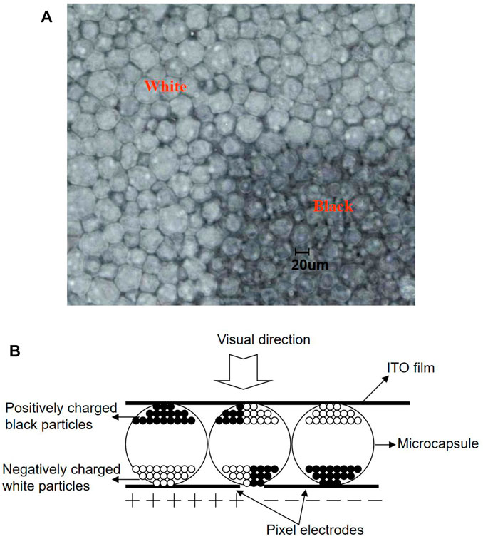
FIGURE 1. The structure of a microcapsule EPD. (A) An enlargement image of microcapsules in an EPD. (B) EPD model.
In the interior of a microcapsule, as is shown in Figure 1B, in order to ensure the good electrophoretic performance of electrophoretic particles, a charged control agent is injected into the display capsule, which can effectively prevent the accumulation of charged particles and deposit on the capsule wall. The display particles in the capsule are mainly affected by gravity, buoyancy, electric power, and the viscosity of nonpolar solvent. In order to avoid the settlement of display particles, gravity is equal to buoyancy, as shown in Eq. 1.
Here,
Here,
Here,
In general, the charged particle zeta potential could reach a level which could make a particle whose radius is 1
where
In the process of driving particles, the EPD may not display a desired gray scale if we drive particles to realize gray scales directly. In the traditional driving waveform, a four-stage driving waveform is used to drive particles to realize gray scales accurately [7]: erase the original image, reset to black state, clear to white state, and write a new image. In a driving waveform, a unit of time is 1/50 = 20
In the design process of a driving waveform, the DC balance is a factor which must be considered. In the traditional driving waveform, the time of positive voltage and negative voltage must equal in the one gray scale change path to reach the DC balance.
The process of activating particles is very important in the driving waveform. The particles in microcapsules may be affected by various forces, and the driving force of electric potential must overcome other external forces to drive the particles. However, the resistance increases with the increase of speed. The forces that hinder the movement of particles are particle gravity, viscous resistance of electrophoretic solution, collision between particles, wall collision of microcapsules, Coulomb force between particles, and so on. When the resistance of particles is greater than the electric field force, the particle velocity will decrease. Only after a long enough residence time, the particles can reach a stable state, and the force acting on the particles can reach equilibrium. This reaction time has a direct impact on the refresh speed of the display screen. At this time, the motion ability of the moving particles is obviously lower than that of the activated particles [6]. Therefore, it is necessary to design a longer voltage duration to obtain the same gray level as the driving waveform with the active particle stage. Therefore, at the beginning of the driving waveform, we always use the limited driving time to activate the particles as much as possible. There are two driving waveforms, which are designed to drive the EPDs from a black state to a white state, in Figure 2A. The final reflectivity difference of an EPD which is driven by two driving waveforms are shown in Figure 2B.
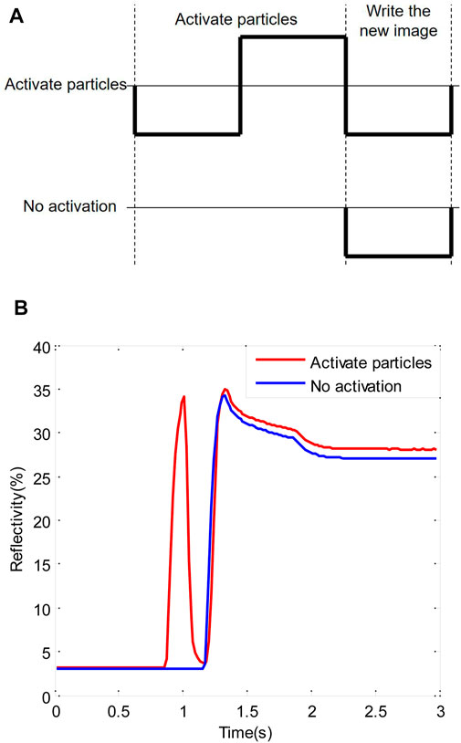
FIGURE 2. Reflectance curves of an EPD which is driven by two kinds of driving waveform (A) EPD driving waveforms. (B) Reflectance curves of an EPD according to driving waveforms, the driving waveform with an active particles stage can obtain higher reflectivity.
In this article, a new driving waveform, which is based on the black reference gray, is proposed. In this waveform, the driving process is fused, and there are two stages which include a resetting to black state stage and writing the new image stage. In the first stage, the particles are activated as far as possible, and a stable reflectivity black state is obtained at the end of this stage; then, the black state is taken as the reference gray. In the second stage, the positive voltage and negative voltage can cooperate with each other to realize the display of multilevel gray scales. An example of the new driving waveform is shown in Figure 3.
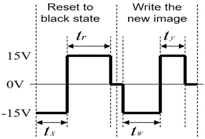
FIGURE 3. An example of the new driving waveform which includes a resetting to black state stage and a writing the new image stage.
The second stage of the driving waveform, which could drive the EPD to realize the original image, must be considered in the design of the new driving waveform. For example,
The driving waveform could reach the DC balance if Eq. 6 is obeyed. In the first stage of the driving waveform, there is not enough time for refreshing between the white state and the black state, so the EPD is written to a middle gray scale, and this method could reduce the activation time greatly [8]. The detail design of the driving waveform is shown in Figure 4. For the sake of convenience, B represents black gray, DG represents dark gray, LG represents light gray, and W represents white gray, respectively. In Figure 4, the original gray scale is LG, both
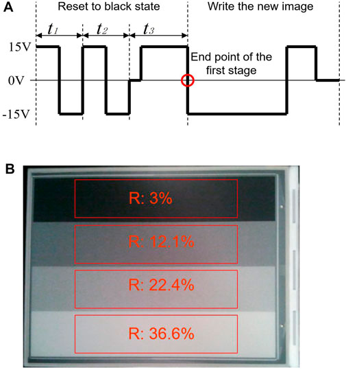
FIGURE 4. (A) Design details of the new driving waveform, at the end point of the first stage, a black state which has a stable reflectance value can be obtained. (B) The real EPD has four-level gray scales which are driven by the proposed driving waveform.
We carried out a driving experiment on an EPD device according to the proposed driving waveform, and the result is shown in Figure 4B. The experimental results showed that the driving waveform could realize multilevel gray scales. Among them, four testing areas are marked, the reflectivity of the first testing area is 3%, the second testing area is 12.1%, the third testing area is 22.4%, and the fourth testing area is 36.3%. According to the principle of gamma correction, the human eye sensitive to brightness transformation when the brightness is low. So, the change of the reflectivity value is nonlinear.
In this article, a new driving waveform based on two stages is proposed, and the driving process of gray scales is effectively fused. The first stage of the driving waveform can erase the original image, and the second stage is used to realize a multilevel gray scales display. In addition, the black state is used as the reference gray scale according to the mechanical analysis of particles in microcapsules. The driving waveform proposed by us has the advantages of short driving time and less voltage conversion times. It can effectively reduce the flicker sense and improve the reading comfort while shortening the screen switching time. What is more, the DC balance rule is applied to the design, which can effectively prevent the display breakdown caused by charge trapping. So, the proposed driving waveform provides a reference for the continuous improvement of the EPD display quality.
The original contributions presented in the study are included in the article/Supplementary Material; further inquiries can be directed to the corresponding authors.
LW designed this project. PM and JZ carried out most of the experiments and data analysis. QW performed part of the experiments and helped with discussions during manuscript preparation. All authors have read and agreed to the published version of the manuscript.
This research was funded by the Key Projects of the Second Batch of Social Welfare and Basic Research in Zhongshan City (No. 2020B2021), the High-level Scientific Research Startup Project in Zhongshan Polytechnic (No. KYG2104), and the Special Projects in Key Fields of Colleges and Universities in Guangdong Province in 2020 (No. 2020ZDZX3083).
The authors declare that the research was conducted in the absence of any commercial or financial relationships that could be construed as a potential conflict of interest.
All claims expressed in this article are solely those of the authors and do not necessarily represent those of their affiliated organizations, or those of the publisher, the editors and the reviewers. Any product that may be evaluated in this article, or claim that may be made by its manufacturer, is not guaranteed or endorsed by the publisher.
1. Heikenfeld J, Drzaic P, Yeo J-S, Koch T. Review Paper: A Critical Review of the Present and Future Prospects for Electronic Paper. J Soc Inf Display (2011) 19(2):129–56. doi:10.1889/JSID19.2.129
2. Meng X, Wen T, Qiang L, Ren J, Tang F. Luminescent Electrophoretic Particles via Miniemulsion Polymerization for Night-Vision Electrophoretic Displays. ACS Appl Mater Inter (2013) 5(9):3638–42. doi:10.1021/am400103d
3. Lee J-K, Kim S-S, Park Y-I, Kim C-D, Hwang Y-K. In-cell Adaptive Touch Technology for a Flexible E-Paper Display. Solid-state Electron (2011) 56(1):159–62. doi:10.1016/j.sse.2010.10.008
4. Yi Z, Huang Z, Lai S, He W, Wang L, Chi F. Driving Waveform Design of Electrowetting Displays Based on an Exponential Function for a Stable Grayscale and a Short Driving Time. Micromachines (2020) 11(3):313. doi:10.3390/mi11030313
5. Kao W-C, Wu G-F, Shih Y-L, Chang W-T, Lin F-S, Hsieh Y-J. Design of Real-Time Image Processing Engine for Electrophoretic Displays. J Display Technol (2011) 7(10):556–61. doi:10.1109/JDT.2011.2159360
6. Li W, Wang L, Zhang T, Lai S, Liu L, He W. Driving Waveform Design with Rising Gradient and Sawtooth Wave of Electrowetting Displays for Ultra-low Power Consumption. Micromachines (2020) 11(2):145. doi:10.3390/mi11020145
7. Bai PF, Hayes RA, Jin M, Shui L, Yi ZC, Wang L. Review of Paper-Like Display Technologies (Invited Review). Prog Electromagn Res C (2014) 147:95–116. doi:10.2528/PIER13120405
8. Zeng W, Yi Z, Zhao Y, Zeng W, Ma S, Zhou X. Design of Driving Waveform Based on Overdriving Voltage for Shortening Response Time in Electrowetting Displays. Front Phys (2021) 9:642682. doi:10.3389/fphy.2021.642682
9. Kao W-C, Liu C-H, Liou S-C, Tsai J-C, Hou G-H. Towards Video Display on Electronic Papers. J Display Technol (2016) 12(2):129–35. doi:10.1109/JDT.2015.2469539
10. Yi Z, Feng H, Zhou X, Shui L. Design of an Open Electrowetting on Dielectric Device Based on Printed Circuit Board by Using a Parafilm M. Front Phys (2020) 8:193. doi:10.3389/fphy.2020.00193
11. Kao W-C. Electrophoretic Display Controller Integrated with Real-Time Halftoning and Partial Region Update. J Display Technol (2010) 6(1):36–44. doi:10.1109/JDT.2009.2030774
12. Yi Z, Zeng W, Ma C, Feng H, Yang J, Liu L. A Real‐time Touch Control System Design Based on Field‐programmable Gate Array via Optimizing Bresenham Algorithm for Electrowetting Displays. J Soc Inf Display (2021) 29:573–83. doi:10.1002/jsid.1001
13. Kao W-C, Chen H-Y, Liu Y-H, Liou S-C. Hardware Engine for Supporting Gray-Tone Paintbrush Function on Electrophoretic Papers. J Display Technol (2014) 10(2):138–45. doi:10.1109/JDT.2013.2289364
14. Lu C-M, Wey C-L. A Controller Design for Micro-Capsule Active Matrix Electrophoretic Displays. J Display Technol (2011) 7(8):434–42. doi:10.1109/JDT.2011.2142173
15. Yi Z, Zeng W, Ma S, Feng H, Zeng W, Shen S. Design of Driving Waveform Based on a Damping Oscillation for Optimizing Red Saturation in Three-Color Electrophoretic Displays. Micromachines (2021) 12(2):162. doi:10.3390/mi12020162
16. Yang S-H, Lin F-C, Huang Y-P, Shieh H-PD, Yang B-R, Chang M-J. P-83: Ghosting Reduction Driving Method in Electrophoretic Displays. SID Int Symp Dig Tech Pap (2012) 43(1):1361–4. doi:10.1002/j.2168-0159.2012.tb06057.x
17. Yi Z, Liu L, Wang L, Li W, Shui L, Zhou G. A Driving System for Fast and Precise Gray-Scale Response Based on Amplitude-Frequency Mixed Modulation in TFT Electrowetting Displays. Micromachines (2019) 10(11):732. doi:10.3390/mi10110732
18. Li WC, Keh HJ. Electrophoretic Mobility of Charged Porous Shells or Microcapsules and Electric Conductivity of Their Dilute Suspensions. Colloids Surf A: Physicochemical Eng Aspects (2016) 497:154–66. doi:10.1016/j.colsurfa.2016.02.028
19. Wang L, Yi Z, Jin M, Shui L, Zhou G. Improvement of Video Playback Performance of Electrophoretic Displays by Optimized Waveforms with Shortened Refresh Time. Displays (2017) 49:95–100. doi:10.1016/j.displa.2017.07.007
20. Yi Z, Feng W, Wang L, Liu L, Lin Y, He W. Aperture Ratio Improvement by Optimizing the Voltage Slope and Reverse Pulse in the Driving Waveform for Electrowetting Displays. Micromachines (2019) 10(12):862. doi:10.3390/mi10120862
21. Kao W-C, Chang W-T, Ye J-A. Driving Waveform Design Based on Response Latency Analysis of Electrophoretic Displays. J Display Technol (2012) 8(10):596–601. doi:10.1109/JDT.2012.2205896
22. Wang Z, Liu Z. The Key Technology of Ereader Based on Electrophoretic Display. In: 2010 2nd International Conference on Software Technology and Engineering, San Juan, PR, October 3-5, 2010 (2010). 333–6. doi:10.1109/ICSTE.2010.5608873
23. Shen S, Gong Y, Jin M, Yan Z, Xu C, Yi Z. Improving Electrophoretic Particle Motion Control in Electrophoretic Displays by Eliminating the Fringing Effect via Driving Waveform Design. Micromachines (2018) 9(4):143. doi:10.3390/mi9040143
24. Zeng W, Yi Z, Zhou X, Zhao Y, Feng H, Yang J. Design of Driving Waveform for Shortening Red Particles Response Time in Three-Color Electrophoretic Displays. Micromachines (2021) 12(5):578. doi:10.3390/mi12050578
25. Yi Z-C., Bai P-F., Wang L, Zhang X, Zhou G-F. An Electrophoretic Display Driving Waveform Based on Improvement of Activation Pattern. J Cent South Univ (2014) 21(8):3133–7. doi:10.1007/s11771-014-2285-9
26. He W, Yi Z, Shen S, Huang Z, Liu L, Zhang T. Driving Waveform Design of Electrophoretic Display Based on Optimized Particle Activation for a Rapid Response Speed. Micromachines (2020) 11(5):498. doi:10.3390/mi11050498
27. Duan F, Bai P, Henzen A, Zhou G. Driving Waveform Optimization in electrophoretic Display Based on DC-balance. Chin J Liquid Crystals Displays (2016) 31(10):943–8. doi:10.3788/YJYXS20163110.0943
28. Bert T, De Smet H. Dielectrophoresis in Electronic Paper. Displays (2003) 24(4-5):223–30. doi:10.1016/j.displa.2004.01.009
29. Kang H-L, Kim CA, Lee S-I, Shin Y-K, Lee Y-H, Kim Y-C. Analysis of Particle Movement by Dielectrophoretic Force for Reflective Electronic Display. J Display Technol (2016) 12(7):747–52. doi:10.1109/JDT.2016.2524023
30. Crowder TM, Rosati JA, Schroeter JD, Hickey AJ, Martonen TB. Fundamental Effects of Particle Morphology on LungDelivery: Predictions of Stokes’Law and the Particular Relevance to Dry Powder Inhaler Formulation and Development. Pharm Res (2002) 19(3):239–45. doi:10.1023/A:1014426530935
Keywords: electrophoretic display, driving waveform, driving process, reference gray scale, direct current balance
Citation: Wang L, Ma P, Zhang J and Wan Q (2021) Driving Waveform Design Based on Driving Process Fusion and Black Reference Gray Scale for Electrophoretic Displays. Front. Phys. 9:723106. doi: 10.3389/fphy.2021.723106
Received: 10 June 2021; Accepted: 05 July 2021;
Published: 09 August 2021.
Edited by:
Qiang Xu, Nanyang Technological University, SingaporeReviewed by:
Weimin Li, Shenzhen Institutes of Advanced Technology, CAS, ChinaCopyright © 2021 Wang, Ma, Zhang and Wan. This is an open-access article distributed under the terms of the Creative Commons Attribution License (CC BY). The use, distribution or reproduction in other forums is permitted, provided the original author(s) and the copyright owner(s) are credited and that the original publication in this journal is cited, in accordance with accepted academic practice. No use, distribution or reproduction is permitted which does not comply with these terms.
*Correspondence: Li Wang, d2FuZ2xpX29ldEAxNjMuY29t; Pengchang Ma, bXBjbXljOTlAYWxpeXVuLmNvbQ==
Disclaimer: All claims expressed in this article are solely those of the authors and do not necessarily represent those of their affiliated organizations, or those of the publisher, the editors and the reviewers. Any product that may be evaluated in this article or claim that may be made by its manufacturer is not guaranteed or endorsed by the publisher.
Research integrity at Frontiers
Learn more about the work of our research integrity team to safeguard the quality of each article we publish.