 Iain McKenzie
 Selwan Ibrahim
 Emile Haddad
 Silvia Abad
 Andreas Hurni
 Lun K. Cheng
95% of researchers rate our articles as excellent or good
Learn more about the work of our research integrity team to safeguard the quality of each article we publish.
Find out more
REVIEW article
Front. Phys. , 15 November 2021
Sec. Optics and Photonics
Volume 9 - 2021 | https://doi.org/10.3389/fphy.2021.719441
This article is part of the Research Topic Optics and Photonics in Space View all 7 articles
For over two decades the European Space Agency has investigated the possibility of using fiber optic sensors in spacecraft engineering as tools to advance the monitoring and control of spacecraft. The applications have been diverse covering both launcher and satellite applications and encompassing environments from cryogenic to high temperature re-entry applications. The aim of this review is to capture the history and status of fiber optic sensors for space applications demonstrating the breadth of applications that have been studied and the lessons learnt along the way. Finally, it is the intention of this review to look forward, pointing to how this technology can be used in the future and identifying what are the key remaining challenges to its further successful exploitation.
Spacecraft monitoring is critical for the successful operation of any space mission. A variety of sensors are required to provide critical information about the spacecraft health during fabrication, testing and service lifetime. Space is a very challenging environment for any sensing system as it is characterized by microgravity, vacuum (causing outgassing) presence of radiation (gamma rays, protons, electrons, heavy ions) large thermal variations, mechanical vibrations and shock resulting from the launch. The specifications for any sensor to be used in a spacecraft are derived by the type of mission primarily defined by the orbital altitude, the operational lifetime, and the location of the sensor in the spacecraft.
Fiber optic sensing systems are considered for space applications due to many advantages that can lead to solutions with the potential to outperform their conventional counterparts. These advantages include:
• Insensitivity to electromagnetic interference, and use of a passive sensor free from sparking or electrostatic discharge.
• Use of a lightweight and flexible harness that can result in significant mass savings.
• Flexible sensor distribution at remote locations in the structure.
• Efficient multiplexing for high sensor capacity, low power requirements per sensor.
• High signal to noise ratio for high measurement accuracy.
• Multi-parameter sensing, remote interrogation.
• Potential to embed in composite structures.
The European Space Agency (ESA) has been funding the development of fiber optic sensor solutions for well over 20 years, this has resulted in several successful developments, most notably the successful introduction of fiber optic gyroscopes (FOGs) which today have found wide spread adoption for high accuracy rotation measurement in many satellite missions. This paper will not cover FOG technology as there have been several excellent reviews already published on this topic which the interested reader is directed to [1–5]. Instead, this paper will focus on the use of fiber Bragg grating (FBG) sensors and will highlight the use of this technology for space applications. A wide range of applications are presented spanning a number of different types of spacecraft and covering a wide range of environments from cryogenic to high temperature reentry shields as depicted in Figure 1 below.

FIGURE 1. Schematic overview of spacecraft applications.
This paper has been divided into several sections covering; An introduction to fibre optic sensing for those unfamiliar with the topic. An overview of the main applications where fibre optic sensing is believed to offer interesting advantages over conventional approaches looking at opportunities in both the satellite and launcher domains. This section is supported by the test results from a number of breadboard demonstrations made over several years of technology development. In addition, the paper highlights several ESA projects aimed at bringing the fiber sensing technology to a higher technology readiness level (TRL) to allow its use in future space missions, highlighting some of the challenges of qualifying this technology for space flight. Finally, a number of successful flight demonstrations of the technology have been included in the paper, demonstrating both satellite and launcher applications. In conclusion, the paper tries to draw together the main lessons learnt and some future perspectives for fibre optic sensing in space applications.
As an introduction to the world of fiber optic sensing for those not familiar with this topic a brief explanation is given in the following text of the fiber sensing techniques described in this paper. Fiber optic sensing is a very broad topic covering the use of fiber optics in the world of sensing as distinct from its use in telecommunications which most people are now familiar with. Fiber optic sensing has always been a topic closely related to developments in the telecommunication industry, and for a large part has fed off the many exciting developments stemming from the commercial development of fiber technology for the telecommunication industry. However, in the last 20–30 years it has developed into an important topic and is expected to grow into a multibillion-dollar industry in the coming years [6] This growth is largely due to the wide variety of ways in which light can be used to measure real physical parameters such as strain, temperature, rotation, pressure, acceleration, and chemicals.
What unifies this very diverse field is that fiber optic sensors are all based on the manipulation of one or more of the parameters of light being transmitted through the fiber to measure a physical parameter. In the case of light, the parameters that can be manipulated to measure physical properties include the phase, wavelength, intensity or polarization, or a combination of these, which results in a huge diversity of possible approaches for the design of fiber optic sensors, and it is a small subsection of these which will be investigated in the following paper.
Fiber optic sensing is often split into two main categories of sensor described as extrinsic and intrinsic. The difference between these two main categories is that in extrinsic sensors the fiber merely acts as a means of delivering the optical signal to and from where the sensing is to be performed, whereas in the case of intrinsic sensing the fiber is both the means for delivering the signal and the sensor itself. An example of extrinsic sensing would be the case of an optical magnetometer as will be used on the ESA’s Juice mission [7]. In this sensitive payload a fiber optic harness is used to transfer a modulated laser signal to a gas cell where the scalar magnetic field is measured through a change in the optical intensity of light coupled into a return optical fiber. Another example of such a sensor used in a space mission is the Basic Angle Measurement (BAM) sensor on ESA’s GAIA mission [8]. In this case a polarization maintaining single mode fiber is used to deliver a laser to a free space interferometer which was used to measure the structural deformation of the spacecraft allowing ESA’s engineers to accurately track the angle between the two telescopes on the satellite, thus allowing the mapping a billion stars in our galaxy to unprecedented accuracy.
In this paper however the focus will be on the rich variety of intrinsic sensors where the fiber itself acts as part of the sensor that have been studied or flown by ESA to bring new sensing capabilities to spacecraft engineering.
A Fiber Bragg Grating (FBG) is a periodic modulation of the refractive index written into the core of an optical fiber which has the effect of coupling light of a particular wavelength from a forward propagating wave to a reflected propagating wave. The wavelength that is reflected by this intra-core grating is called the ‘Bragg’ wavelength and is determined by the period of refractive index modulation as is illustrated in Figure 2. The relationship between the Bragg wavelength (λB) and the period (Λ) is given in Eq. 1, where neff is the average effective refractive index of the fiber.
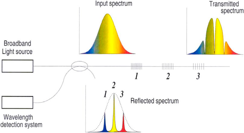
FIGURE 2. An example of an FBG based sensing system showing the Spectra of the FBG in reflection and transmission.
At the first glance, a Fiber Bragg Grating acts as an “optical ruler”: by stretching or compressing the FBG, the grating period Λ changes and therewith directly the Bragg wavelength.
However, there are additional parametric influences. Both the grating period Λ and the effective refractive index neff depend on both strain ε and on temperature T. For the relative Bragg wavelength, this yields the basic strain sensing relation at variable temperature using FBGs:
where λB0 is the “zero” Bragg wavelength at measurement start, K-factor represents the strain sensitivity, and ς represents the thermal (cross) sensitivity. For operation wavelengths in the 1500–1600 nm range, the strain sensitivity has a typical value of 1.2 pm/µε, while the temperature sensitivity has a typical value of 10 pm/°C.
Since the reflected wavelength is dependent on both strain and temperature, it should therefore be possible to measure the effect of either of these parameters on the fiber, with the important constraint that there must be a means to distinguish between strain and temperature. This becomes an important consideration when designing a transducer for measuring either strain or temperature as will be explored later in the paper. Indeed, with careful design of the transducer it is possible to measure not only strain or temperature but other parameters such as chemistry if these parameters can be converted into a strain or temperature effect on the fiber. An example of such a transducer is a Palladium coating placed around the fiber in the region of the grating. Palladium is known to expand in the presence of hydrogen gas and thus the concentration of hydrogen around the fiber can be measured [9]. Other parameters that can be measured include pressure and acceleration [10, 11].
One of the key benefits of FBG technology is the ability to multiplex many sensors along a single strand of optical fiber using either wavelength division multiplexing (WDM) or time division multiplexing (TDM) or a combination of the two techniques. WDM multiplexing is when several gratings are written into fiber with different periods so that each sensor position can be discriminated as a uniquely coded wavelength reflection. TDM is also possible by means of using a radar approach, where individual gratings can be discriminated based on the arrival time of the return pulse at the detector. FBG sensors also comes in different variants, such as chirped gratings, long period gratings, tilted gratings, etc., [12]. A more detailed discussion of Fiber Bragg gratings is outside the scope of this review paper but is available in the following excellent review papers which explore the topic in greater detail [13, 14].
Interferometers are an important class of sensors in which two waves (typically electromagnetic) are superimposed on each other to measure a physical parameter. This investigative technique is used in many fields including astronomy, metrology, spectroscopy, quantum mechanics, particle physics and many more [15]. In fiber optic interferometric systems, the phase of light is used to measure physical parameters acting on the fiber by the interference of two optical paths guided inside the optical fiber. Several different configurations are possible where the main types typically used are Mach Zehnder, Michelson, Fabry-Perot and Sagnac interferometers [16, 17]. Fiber based interferometers are a class of very sensitive sensors because they measure the relative phase difference of the light propagating in two optical paths within the fiber. Compared with classical bulk systems, fiber-based systems have several attractive features including the capability to provide remote sensing, compact form factor, rugged packaging, and the potential to be relatively low cost. This combined with the fact that they are composed of a dielectric material, chemically inert and can be designed to withstand high temperatures, make them suitable for use in many harsh environments. As a result, they have found applications across many fields from underwater acoustic detection, current and power measurements in high power electric systems, to the detection of pressure and temperature in-vivo [18–23].
Another common fiber sensing technique used is distributed sensing where the term “distributed sensing” refers to the case in which the whole optical fiber acts as a continuous linear sensing element itself, contrarily to discrete and quasi-distributed optical fiber sensors, in which a physical variable can be measured only in a small number of pre-defined locations, such as with Bragg gratings. Thus, in distributed sensing each spatially resolved measurement is related to a particular fiber section. Distributed sensing systems in optical fibers are based on one of the intrinsic scattering mechanisms naturally present in glass. These scattering mechanisms include the following three, Rayleigh, Brillouin and Raman. Each of these scattering mechanisms can be linked to the measurement of either strain or temperature, and in some cases much like the Bragg grating the scattering mechanism can be sensitive to both as is the case for both Rayleigh and Brillouin [24, 25].
Monitoring needs of spacecraft are rapidly increasing due to new and more challenging missions along with demands to reduce launching costs. This can be achieved by minimizing the manufacturing, assembly, integration, and test time in addition to employing new low weight materials balanced by the need for maximizing system lifetime while maintaining good reliability. Hence, hundreds of sensors, primarily temperature ones, are employed during the lifetime of a spacecraft and thousands during the assembly and testing phase.
Conventional electronic sensors are characterized by their low multiplexing capability and their EMI/RF susceptibility and it is in this scenario that Fiber Optic Sensors (FOS) in general, and more specifically Fiber Bragg Grating (FBG) technology offers important benefits, improving in various ways the already deployed sensing subsystems (e.g., reducing the weight associated with sensor cabling, increasing the number of sensing points) and enabling new monitoring applications that were not possible by using conventional sensing technologies.
Early platform studies focused on large telecom satellites, as being the most suitable platforms to incorporate fiber optic sensing technology on the basis that these platforms require many sensing elements and represent a good recurrent business case for the development and implementation of the technology. The EUROSTAR 3000 satellite was taken as a relevant example. A first outcome of Airbus Defence and Space definition of requirements was to focus the interest on temperature sensing. Temperature measurements involve the greatest number of sensors on the overall satellite sensor count, and thus mass and assembly, integration and test time advantages can be maximized for temperature related applications. FBG sensors can be applied to two quite different application environments: in-flight monitoring and ground testing. A review of the potential applications can be found below:
Thermal mapping: reduction of mass, assembly/integration due to embedding in an early assembly stage, high number of sensors due to multiplexing capability.
Strain and vibration monitoring: of interest for design verification during ground testing, launch and orbit. Also interesting for damage detection on structures.
Satellite structural panel/smart panel: apart from equipment accommodation, standard spacecraft panels also provide thermal monitoring and control for the attached equipment, mostly electrical boxes. By embedding fiber optic temperature sensors into those panels, the thermal control could be optimized and the harness for additional temperature sensors reduced. Furthermore, assembly time could be reduced by the integration of the fiber optic sensors during the panel manufacturing.
Propellant tanks: a further interesting application of fiber sensing are propellant tanks. During operation, the pressure of the tank and fuel pipes could be determined by fiber optic-based strain sensors by the overall stress distribution. Strain sensors could also be used to monitor the tank integrity during manufacturing, testing and launch. Finally, Is there fiber sensors could also be used to determine in a more accurate way the quantity of remaining fuel inside the propellant tanks.
Reflector deformation control: reflectors are currently not instrumented for deformation control. However, the increase of transmission performance imposed higher technical requirements for stability, pointing and size while the low mass requirements remain.
Array antenna thermal testing: temperature tests over antenna parts are normally requested in order to provide early detection of design problems which often translate into non-uniform temperature distributions. The availability of fiber optic temperature sensors immune to RF and with a thickness that is compatible with the interlayer gaps on this type of antennas makes them an ideal solution to perform accurate thermal testing.
Electric propulsion subsystem thermal monitoring: relevant monitoring requirements have been found for the different parts of the electric propulsion subsystems. Within these subsystems, the high voltage power supplies, high voltage cables, thrusters and the Xenon tank and pipes, all have temperature monitoring requirements. A key difficulty here is the presence of a vacuum environment where a combination of high EM fields and free charged particles limits the possibilities of using conventional electrical sensors. In this application, FBG sensors can be an enabling technology for temperature monitoring, since they are dielectric in nature, and EMI immune.
Several demonstrators have been built to understand the performance, complexity, and challenges of using FBG sensors in place of conventional electrical counterparts. These demonstrations are elaborated in the following sections.
One of the challenges encountered during antenna power RF testing, and specifically in array type antennas, is to determine the temperature of certain elements of the antennas, either internal or external, while subjected to RF path. Temperature tests over antenna parts are normally requested to provide thermal vacuum testing for early detection of design problems which often translate into non uniform temperature distributions. On such applications the effect on the RF behaviour produced by the metallic cables of thermocouples and/or thermistors at certain frequencies is a limiting factor when using standard sensors. In some cases, temperature measurements had to be estimated even using qualitative temperature indicators, such as paper films on which color changes as a function of the maximum attained temperature. Such a sensor provides a reference of the temperature achieved, but clearly lacks the accuracy of a conventional sensor. The availability of fiber optic temperature sensors immune to RF and with a thickness that is compatible with the interlayer gaps on this type of antennas makes them an ideal solution to perform accurate thermal testing.
FBG based sensors for this application were developed and tested by HBM FiberSensing in the frame of ESA’s ARTES-5 project “Fiber Optic Sensing Subsystem for Spacecraft Health Monitoring in Telecommunication Satellites”. Aside from the RF immunity, a key issue for this application is the sensor installation flexibility. Sensors must also be compatible with antenna inter-layer separation, which is a few millimeters. The fiber coating and protection must show a good trade-off between ease of installation and impact on antenna performance due to size. The sensor design is shown in Figure 3A. The terminal nature of the sensors provides easier installation inside the antenna layers and intrinsic strain decoupling. Demonstration of the capabilities of this solution was performed on two different antenna samples from EADS CASA (currently Airbus Defence and Space): a strip-line Wilkinson divider breadboard used for the center divider of the NAVANT (transmit antenna for GALILEO system) and a 1:3 Divider used in a NASA’s Mars ROVER antenna as shown in Figures 3B,C. S parameter measurements were taken before and after FBG installation to assess the impact of the inclusion of the sensors in the antenna RF performance, with small variations observed only due to sample reworking.
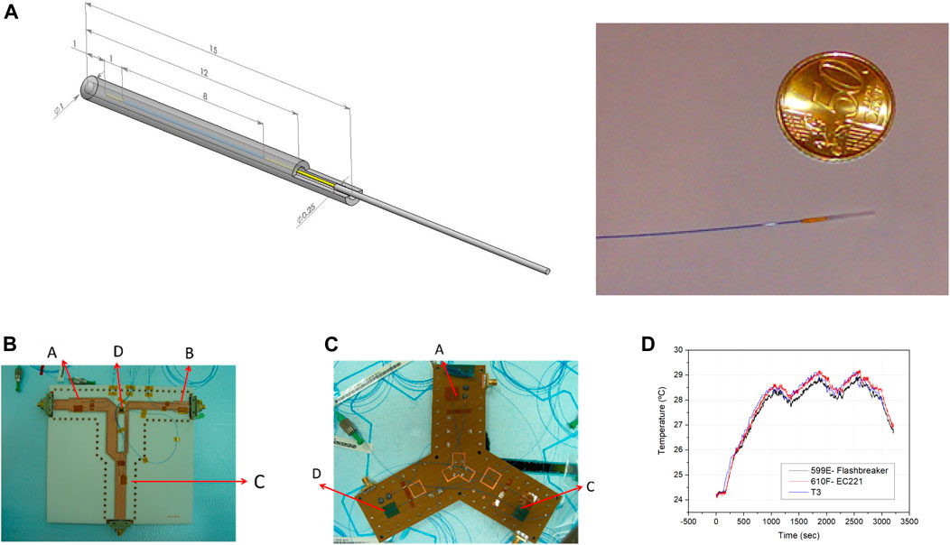
FIGURE 3. (A)Terminal temperature sensor design and picture by HBM, (B) 17 FBG sensors (HBM FiberSensing design) placed on inner layers and surface on a Wilkinson divider from GALILEO’s NAVANT antenna, (C) 9 FBG sensors placed on inner layers and surface on a Mars ROVER divider sample, (D) comparative results between FBGs and thermocouples on the Wilkinson divider.
To assess the thermal performance of the FBG sensors, additional thermocouples were included on the surface of the Wilkinson divider for comparison. Figure 3D shows this comparative analysis, with very good agreement being observed between both types of sensors [26].
In addition to installing optical fiber sensors on the surface of a structure, they can also be integrated and embedded within space structures and membranes. A major advantage here is the capability to follow the evolution of the structure internal stresses and its temperature since the early manufacturing and along the whole lifetime providing the complete history and determining the specific step where any failure would happen, permitting to analyze the failure reasons and learning how to avoid them. Interesting applications are to sense the antenna reflectors or inflatable structures and membranes in space, measuring the evolution of the strain and temperature. The inflatable components are folded during the launch, then expanded or deployed once in orbit. The deployed material may need to be rigidized once in orbit, after being unfolded, to keep their final shape.
MPB integrated FBGs sensor lines in various engineering models of Carbon fiber reinforced polymer (CFRP) composite antennas for the Canadian space company MDA. The sensors were used to monitor the manufacturing processes in an autoclave of composites with novel methods embedded within the composite in novel composite preparation methods (Resin Infusion). Before embedding in the antennas, MPB studied the FBG response in CFRP that were cut in strips (12.5 × 200 × 0.45 mm), each with one fiber line, containing 3 FBGs, suitable for pulling and thermal cycling tests at MDA.
The strips were submitted to 5 cycles (−170°C to +135°C) in N2 environment. Their response to strain measured before and after the cycling was very similar, showing no delamination between the CFRP layers due to the difference in extension between the fibers (glass) and the epoxy resin. To avoid the exit of the optical fiber at the edge, MDA proposed an innovative idea to exit the fiber through the knots of a layer slightly before the edge before depositing the layer with the others and curing. This operation is somehow challenging as the layer once deposited, cannot be removed for adjustment.
It should be noted that the development of damages of composite is less predictable than metal constructions. The most important damages in composite are impact, delamination and debonding. These damages can be monitored and noticed at an early stage by installing FBG strain sensors at appropriate locations of the composite structure. Due to the complex structure and increasing thickness of the composite constructions, there is also an increase in interest to monitor the strain development inside the composite by embedding the FBG during the production. The embedded FBG can also provide information about the residual strain level in the composite during the curing process for a better prediction of the remaining maximum operational strain. However, due to the strong inhomogeneity of composite (combination of solid fibers and relatively soft resin), embedding a conventional FBG will lead to extreme distortions of the FBG reflection spectrum if the strain along the grating is not homogeneously. This is the case if the FBG fiber is not perfectly aligned with the local fiber/ply of the composite, but some fibers are crossing the FBG fiber and generate lateral point load to the fiber via the Poisson effect, the results in a local axial strain and hence a local change of the grating period. The effect of a single point load for various weights (up to 700 g) causes distortion in the reflection spectrum which increases with increasing load.
A special microstructure fiber has been developed by TNO to reduce this lateral load sensitivity [27]. For the single point load experiment, the single reflection peak shows no spectral distortion up to a weight of 600 g. Therefore, FBG in this new microstructure fiber can be embedded in composite regardless of the orientation of the composite fiber/ply [28]. As other microstructure fibers, the lateral load insensitive fiber has hole structure along the fiber. By incorporating a special shape of the holes between an inner cylinder with the single mode fiber core/cladding and an outer ring as the second cladding, the inner cylinder and the outer ring are connected by the connection beams along the entire fiber. The shape of the connection beams is designed to not pointing in the direction of the core. A lateral point load applying to the outer ring will be converted to a rotation of the inner cylinder by this configuration without local compression of the core. The first prototype is manufactured with 4 connection beams. FBG is successfully realized in this microstructure fiber. FBGs in this prototype microstructure fiber are also embedded in different composite samples with glass fibers or carbon fibers. The effect of FBG orientation in respect to the composite fiber/ply direction on the FBG reflection spectrum is compared to standard FBG. For FBGs not aligned with the composite fiber/ply directions, the FBGs in the microstructure fiber demonstrated a better reflection spectrum [28]. For the second prototype the design is optimized by FEM and results in a 3 connection beams design.
A potential application area for fiber optic sensing, is the Solar Electric Propulsion (SEP) area. The most relevant characteristic in this application is the presence of a vacuum environment where a combination of high voltage, high EM fields and free charged particles limits the possibilities of using conventional electrical sensors. In this context, FBG sensors provide improved signal integrity due to immunity to the EMI environment, and could be an enabling technology for such an application [29].
Within the ion engine propulsion subsystem, three main parts have been identified as having relevant monitoring requirements which could greatly benefit from the properties of fiber optic sensors: Temperature monitoring inside the ion engine thrusters, Temperature monitoring along the high voltage cable from the High Voltage Power Supplies (HVPS) to the engine, and Temperature monitoring in the High Voltage Power Supplies.
In the frame of ESA’s ARTES-5 project “Fiber Optic Sensing Subsystem for Spacecraft Health Monitoring in Telecommunication Satellites”, HBM FiberSensing and EADS CRISA implemented a mockup Electric Propulsion demonstrator equipped with FBG sensors on those three elements as shown in Figure 4A [29].
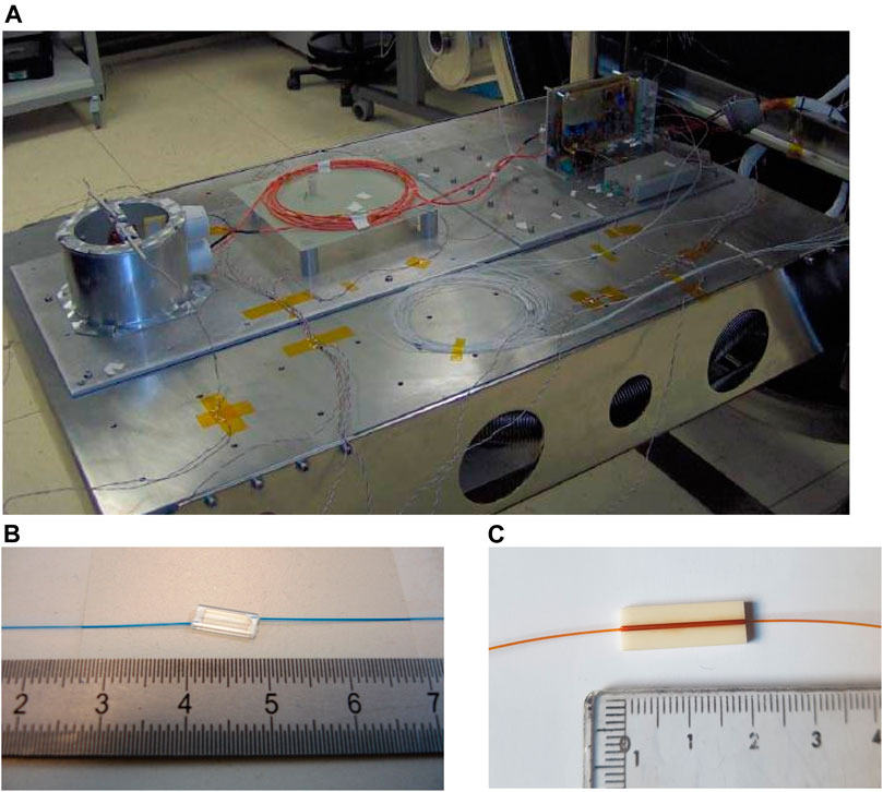
FIGURE 4. (A) Instrumented Electric Propulsion System Mockup entering the vacuum chamber for testing, (B) Miniature serial FBG designs by HBM FiberSensing Design#1, (C) Design #2.
Different FBG sensor designs were employed: the terminal sensor design already shown in Figure 3, the serial temperature design shown in Figure 4B (Figure 4C shows a second version of that same serial sensor approach which improved manufacturing yield) and a third design specifically foreseen for the cable testing, with the FBG imprinted fiber inserted into a 700 micron polyimide flexible tube which was then routed along the cable.
Sensors were tested in high voltage, high magnetic field, high temperature including hot spots, in ambient air pressure, in thermal vacuum and in the critical pressure area where corona may be easily generated when high voltage is applied.
Two test campaigns were carried out in a thermal vacuum (TV) chamber. Heat, plasma and thermal gradients were generated and controlled, in order to measure the FBG sensor performances under these environmental conditions. Thermo couples were mounted where possible to compare the two temperature measurement methods.
Testing showed that the FBG based temperature sensors show better or equal performances than classical thermocouples. As expected, the sensors perform in an excellent way in presence of EMI, high voltage and even plasma. In addition, FBG sensors also perform better than thermocouples in the presence of high thermal gradients due to the lower thermal leakage through the cable [29].
A chirped long FBG sensor correlates the wavelength response to the physical distance on the FBG. Two detectors were used by MPB to detect the effects of a pellet hitting directly the FBG sensor. A very fast detector (1 GHz) measuring the total reflected intensity by the FBG, such a detector is available as a cost effective commercial off the shelf (COTS) component. This can give information of the part of the fiber still connected to the system and the fast dynamic of the impact. Measuring the complete spectrum before and after the impact giving details on the part completely deleted or partially damaged. Figure 5 shows the complete FBG reflected spectra before and after the impact. The impact breaks a small part (1.2 mm) of the fiber, as can be deduced from the missing part of the spectrum.
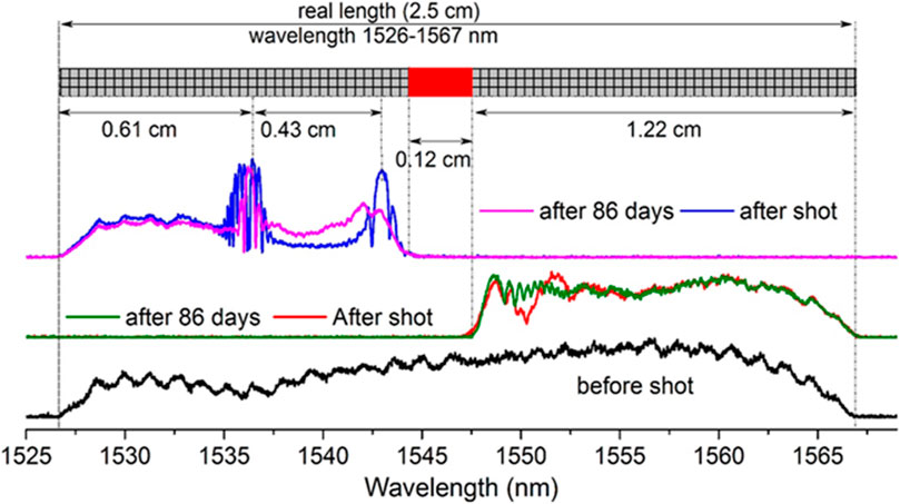
FIGURE 5. Spectra of the FBG before and after impact traced in cascade for better clarity. FBG spectra before the impact (black), the red and purple graphics are the FBG spectra (left and right side) just after the impact, the blue and green graphics are the FBG spectra (left and right side) after 86 days. The empty part in the middle is the broken part.
The left and right side show strong stresses after the impact, with some recuperation (healing) after 86 days. We note that the impact effect (2 mm Al pellet at 2 km/s) is localized within 2 cm radius around the center of the impact. Spectrometers used for FBGs have a limited acquisition speed, which is slow to catch the impact evolution.
During ground testing, a large telecom satellite is subjected to several qualification and acceptance tests. These tests typically require the instrumentation of the satellite with additional sensors which are removed post-test. During the thermal vacuum test a large telecom satellite will be instrumented and equipped with over 400 thermocouples and associated harness. They must be carefully placed and routed around the spacecraft and afterwards dismantled for flight configuration. This leads to increased Assembly, Integration and Testing (AIT) effort, weight and overall cost. Replacing electrical sensors with optical fiber sensors for testing satellites should have the advantage of reducing the harness mass and AIT [30]. In addition to strain and temperature sensing, approximately 250 accelerometers are employed to measure the structure and qualify it for the launch loads during the mechanical testing (shock and vibration) of the satellite. The following section will cover temperature measurements.
Integrating mechanically packaged fiber Bragg grating (FBG) based optical temperature sensors into a honeycomb satellite test panel has been recently demonstrated as part of an ESA ARTES project (Photonically Wired Spacecraft Panels). When using FBG sensors for temperature measurements on satellites and any other structure, special designed sensor packages is required for strain decoupling as standard FBG based sensors are sensitive to both strain and temperature. The simplest way for achieving a strain independent temperature sensor is the design of packages which mechanically isolate the FBG element from the strain.
For these designs to be applicable in space, they must be simple and lightweight. The HBM FiberSensing sensor designs used for electric propulsion (Figures 3, 4), have both shown to provide good strain decoupling, maintaining a very low weight.
Also following this same approach, FBG lines prepared by MPB for the PROBA 2 demonstrator follow a classical design, being the first system to be launched in space. For the standard measurements of temperature (−50°C to +125°C) around the propulsion tank, the passive fiber was protected by a teflon tube permitting a flexibility in the manipulation and positioning. The FBGs were protected locally by small metallic tube mainly to prevent the effect of strain along the or perpendicular to the fiber, then attached to the tank structure with Al tapes.
An alternative solution for simultaneously providing strain and temperature measurements involves using birefringent FBGs inscribed in Polarization Maintaining (PM) fiber (PM-FBG). PM-FBG sensors can also be multiplexed on a single fiber and therefore offer a simplified installation option by mounting them on the surface of the structure without the requirement for complex transducer packaging designs. Such sensors have a double Bragg peak that enables the simultaneous measurement of strain (ɛ) and temperature (T).
From temperature and strain calibrations, it is known that the response of the double peak with respect to strain is different compared to the response to temperature. In this way, the FBGs written in PM-fiber can discriminate to a large extent between strain and temperature. The sensitivity of the peak separation is a key parameter for the decoupling between ε and T.
For a 5× PM-FBG array (PM draw tower grating with Ormocer coating PM-DTG) factory calibration, a strain (0µɛ → +2145µɛ → 0µɛ) and a temperature (−20°C → +120°C → −20°C) calibration cycle was carried out using a birefringent interrogator developed by Optics11 FAZ (FAZ Technology) to calculate the sensor sensitivities. The PM-FBG array was a PM-DTG (draw tower grating) type sensor array manufactured by FBGS using Ormocer coating.
The calibration coefficients can be obtained from calibrating each PM-FBG sensor, one sample PM-FBG sensor from an array, or an average of all PM-FBG sensors within an array. A strain calibration setup was used to evaluate the temperature error caused by induced strain when varied from 0 to 2145 µɛ with 10 steps up and 10 steps down as shown in Figure 6A. The maximum strain induced temperature error for the 5 × PM-FBG sensors using the above calibration coefficients was <1°C (maximum absolute error). Figure 6B shows the strain induced temperature error (crosstalk) or the 5 × PM-FBG array tested using the strain calibration setup [31, 32].
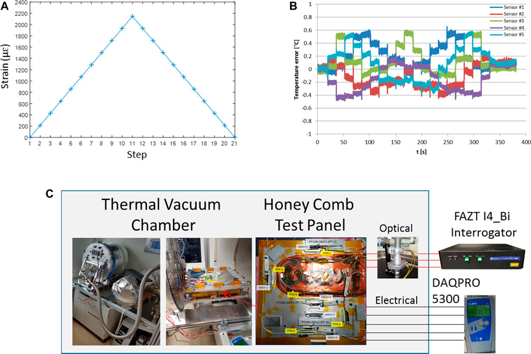
FIGURE 6. (A) Linear longitudinal strain steps (0µɛ → +2145µɛ → 0µɛ) applied to a 5 × PM-FBG (Ormocer coated PM-DTG), (B) Strain induced temperature measurement error for a calibrated 5 × PM-FBG array (Ormocer coated PM-DTG) for the corresponding strain (0µɛ → +2145µɛ → 0µɛ), (C) Thermal vacuum chamber setup showing test panel containing PM-DTGs and sandwiched between heating/cooling plates.
As part of an ESA GSTP project, Optics11 FAZ (FAZ Technology) demonstrated an optical strain independent temperature measurement system using PM-FBGs installed on a honeycomb structure test panel designed for the small-GEO series satellite of an ESA ARTES 5.1 project (Photonically Wired Spacecraft Panels) (4000111220/14/NL/AD). The PM-FBG based temperature sensors were mounted on the surface of the small test panel at certain positions as shown in Figure 6C.
Two main types of mounting techniques were used for two PM-DTG arrays. This involved installing one 5 × PM-DTG array in a 0.7 mm PTFE loose buffer tube and then attaching the PTFE tube on the panel at specific locations using Silicone (3140) RTV coating on 2 sensor locations, aluminium tape on 2 locations, and 1 sensor location left loose.
The other 5 × PM-DTG array measurements focused on 2 PM-DTGs directly glued on the panel using Silicone (3140) RTV coating, and 1 left loose. The test results also show the difference between different sensor mounting techniques on the panel and how they perform when temperature is cycled >= 10 times at atmospheric pressure. Vacuum thermal tests were performed from −20 to +80°C, showing a temperature accuracy error varying between 0.5°C and 1.7°C peak to peak over the full temperature range, in both atmospheric pressure environment and thermal vacuum environments [31, 33] using a simple PM-FBG sensor array without custom packaging.
Future science missions will need higher bandwidth in the Gbit/s range for intra-satellite communications, so the step from electrical transmission media towards fiber-optical media is the logical next step to cope with future requirements. In addition, the fibers can be used to monitor temperatures directly underneath satellite payloads, which will reduce the integration effort in a later phase [34, 43].
In the PhWP study, the environmental requirements for the panels were derived in the first stage and the functional requirements were defined in the second stage. To define the functional requirements, a telecommunication satellite platform, in the case here the Small-GEO series from OHB, was taken as a baseline. Based on the configuration of temperature sensors, communication lines and electrical signaling, a possible replacement by fiber-optical technology was defined and traded w.r.t. its economic benefit. It has been pointed out that the replacement of temperature sensors will reduce harness mass, but the great benefit is seen here in the reduction of assembly effort. Once the satellite panel is manufactured, the temperature sensors are already implemented at certain positions.
To keep track on an economic solution, a detailed market research was carried out to find suitable components for fiber-optic connectors, fibers, and protections buffers. Specially for the connectors, a solution based on military qualified connectors pointed out to be the most interesting solution in terms of price and functionality, especially when using multi-pole connectors. The target of this study was to figure out the possible signals that can be replaced by fiber optic sensing. First, the technology aspect had to consider which signal can be replaced, and which signals make sense to be replaced in an economic way. A summary of the signals and the possibility of replacement is given in Table 1 [34, 43]. The overall target of the panel demonstrator was to prove the concept of the integration of FBG sensors inside the panel for temperature monitoring and additional fibers for communication purposes.
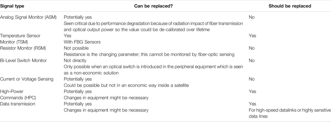
TABLE 1. Possible signals that could be replaced by fiber optic signalling.
The goal of the breadboard demonstrator was divided into different sections:
• Demonstrate the functionality with components and processes which can be further extended to space missions. The component selection takes the advantage of parts used in military applications with similar environmental conditions such as vibration, temperature, and shock loads. The designed breadboard shall be able to sense temperatures at multiple positions with FBG sensors implemented directly in the panel and it shall be able to allow a fiber-optical data communication. For this only the fiber is implemented. Designing of a transceiver is out of scope in this project. The system will afterwards be tested against temperatures and vibration loads to prove the concept.
• It shall also be demonstrated how much mass can be saved by using a fiber-optic sensing concept instead of the point-by-point wiring of the temperature sensors. For this a state-of-the art (SOA) telecommunication satellite is analyzed and the mass savings are estimated.
• An estimation of AIT time will be carried out for both systems to estimate the overall savings taking both effects into account, the reduced mass, and the maybe longer AIT time during panel manufacturing.
• Concerning the test philosophy, the breadboard shall be tested against local temperature variations to prove the functionality of the temperature measurement subsystem and the full assembled and connected system (three panels and two interconnecting patch cords) shall be tested against vibration.
For the estimation of the mass and AIT savings of fiber-optical temperature sensor monitoring (TSM) with respect to classical electrical TSM, a smaller platform with a number of approx. 500 temperature sensors was considered [34]. The AIT time needed for each sensor including time for documentation and for hardening of the glue has been determined based on data provided by experienced staff. For the FBG sensor it is assumed that the sensor comes pre-assembled to the AIT personal. The time for manufacturing a single FBG transducer was evaluated by experiment to approximately 15 min. To highlight the benefit of fiber optic sensing (FOS) in regards of mass and AIT effort savings, the result of this study is listed in Table 2. The study closed with the construction and structural testing of a breadboard demonstrator consisting of three different panels, one large panel (ca. 1 m2) and two smaller panels (ca. 0.3 m2). The large panel and one of the small panels were made from aluminum face sheets, whereas the other small panels was made out of CFRP [34].
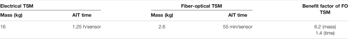
TABLE 2. Mass and AIT effort of electrical TSM vs. fiber optic TSM.
To improve the reliability and reduce the cost of launcher systems, multiple sensors are installed and used for such systems. The Ariane 5 uses over 500 wired electrical sensors for functional and telemetry purposes which requires a lot of effort in installation and testing in addition to the extra weight generated by the electrical cable harnesses solutions. Wireless solutions have been proposed, however techniques to deliver power to the sensors and electromagnetic interference (EMI) is still a challenge. Several demonstrations of fiber optic technology have been conducted in collaboration with our industry partners over the years to prove the technology for active service.
VEGA is a small European launcher with a capacity to place satellites into polar and low-Earth orbits. This four-stage launcher is tailored to carry small scientific spacecraft and other lighter-weight payloads. The interstage between the first and the second stages (Interstage 1/2) has a forward and aft part to be separated at jettisoning of the first stage during flight. Dutch Space in Netherlands was responsible for the development, qualification, and manufacturing of the Vega Interstage 1/2. This all-aluminum conically shaped section is designed as a monocoque structure. This subsystem of Vega has undergone in 2005/2006 different qualification tests of force loading combined with an extensive set of measurements (forces, displacements, and strains) at TNO in Delft as sown in Figure 7. In parallel to conventional strain gauges, FBG sensor arrays, consisting of five strain sensors and one temperature sensor have been installed on different locations of the interstage as sown in Figure 7B. Direct comparisons of the results with conventional sensors during load tests up to several hundred tons are therefore possible. The mounting of the FBG is regarded to be a vital issue for the application of the sensor. Dedicated glue procedures are developed for surface mounting of FBGs for the load measurements of the Vega Interstage 1/2 Qualification Model (QM). Preliminary tests of FBG surface mounting by just attaching and gluing the fiber to the construction has shown hysteresis at a low strain level of about 500 µε for a certain type of glue. This is caused by insufficient strain transfer from the surface to the fiber. During the investigation, 12 different types of glue are investigated including standard glues for conventional strain gauge. Four glues are selected for the final test with an improved FBG surface bonding procedure. Tension test was performed up to about 1900 µε. Two of the four FBGs have shown a stable response at the maximum strain level [35].
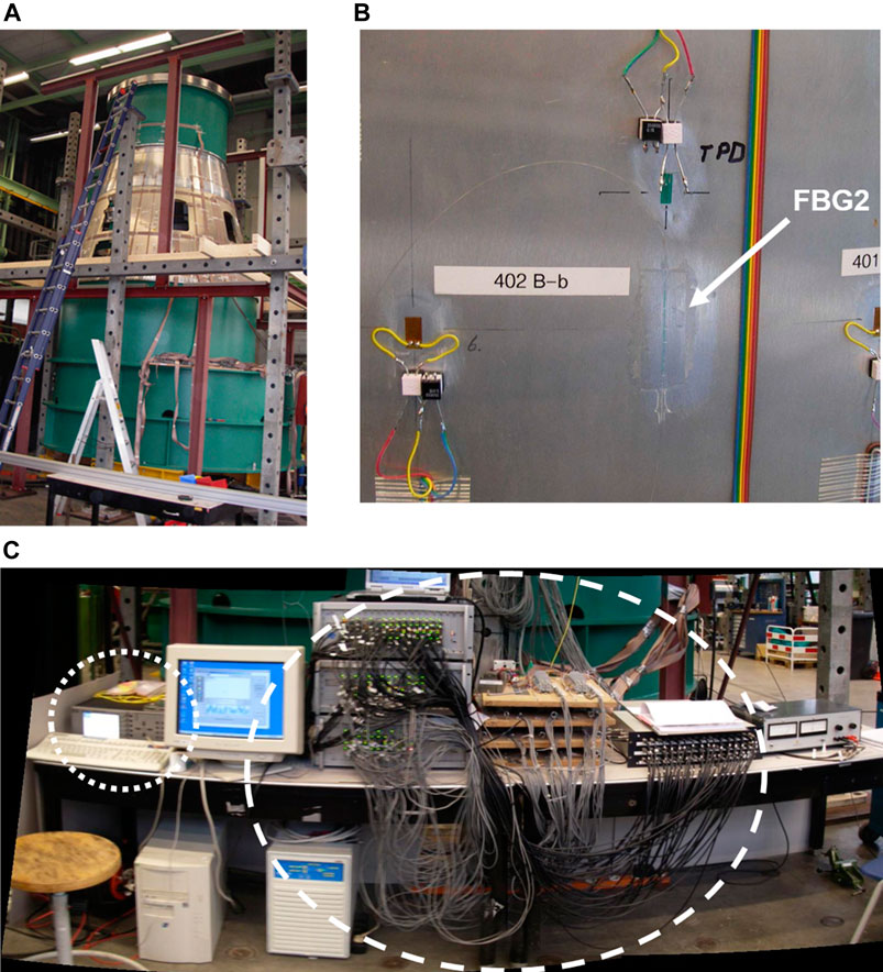
FIGURE 7. (A) Vega Interstage 1/2 installed on test bench, (B) Conventional strain gauge “TPD” and surface mounted “FBG2” located on the same vertical plane on the Vega Interstage 1/2 to measure the strain during compression load, (C) Comparison between the FBG interrogator MO SI425 (dotted line) and the conventional system for 40 electrical strain gauges (dashed line).
Two detection systems for the FBG sensor array have been used: a commercially available interrogator (Micron Optics SI425) as shown in Figure 7C, and a high-speed interrogation system (Deminsys) [36]. During the rapture test, the Deminsys with a maximum sampling frequency of about 20 kHz was able to visualize different high-speed events e.g., crack development [36, 37].
Optical fiber sensing solutions also overcomes the requirement to deliver power to sensors in launchers and is immune to EMI. This was demonstrated by a Telemetry Subsystem (TMSS) Demonstrator under the ESA Future Launcher Proprietary Programme 2.2 (FLPP2.2). A list of electrical sensors that have been deployed on the ESC-A and ESP stages of the ARIANE5 were selected and tested with their counterpart optical sensors as shown in Figure 8. Data acquired from the optical sensors was processed by the I4 interrogation system from Optics11 FAZ (FAZ Technology) and then encapsulated into UDP/IP packets and transferred to the KAM-500 system from Curtis Wright (ACRA).
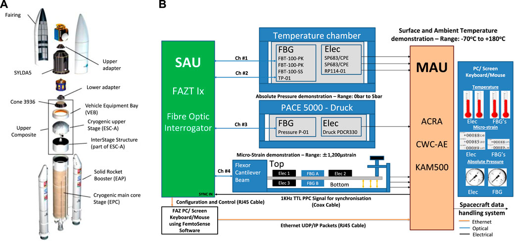
FIGURE 8. (A) Diagram of Ariane 5 Sections, (B) TMSS Demonstrator Overview 5.
The KAM-500 encapsulated the optical sensor data together with the data acquired from electrical sensors and transmitted the data over MIL-STD-1553 and Ethernet data interface. For the strain measurements, the results show the optical and electrical sensors can measure to within 1% FS (Full Scale) of measurement range ±1200 µε. The temperature measurements resulted in the optical and electrical sensors performing on a par with each other, with all sensors recording an accuracy within 0.35% FS over the full temperature range of −70°C to +180°C. The pressure measurements were performed over a 0–5 bar absolute pressure range and over different temperatures across a −40°C to +80°C range. The tests concluded that the optical pressure sensors performed on par with the electrical pressure sensor for each temperature set, where both sensor technologies measured a pressure accuracy of 1.2% FS. The proposed hybrid system can be potentially used for next generation launcher applications delivering weight reduction, improvement in measurement coverage and reduction in Assembly, Integration and Testing (AIT) over traditional electrical systems.
In the ESA TRP project CryoSense (Advanced Measurement Technologies for Cryogenic Flows in Reduced Gravity) different technologies to measure cryogenic liquids under various operational conditions are evaluated. Fiber optic sensor is one of the candidates in particular of interest for liquid fuels. Both the Rayleigh scattering OFDR based, and FBG based technologies can be used for temperature measurement [38]. The advantages of the OFDR based technology are distributed measurement along the sensing fiber in combination with potentially sub-mm spatial resolution. However, the readout frequency is low in comparison to FBG based sensor and hence the OFDR technology is less suitable to measure sudden changes in temperature e.g., sloshing of liquid fuel or the fuel distribution near zero-gravity. For both technologies, the temperature response of the fiber decreases with the temperature. At liquid hydrogen (LH2) temperature, the response almost vanished. For an FBG in standard fiber the temperature sensitivity at room temperature is about 10 pm/K and drops by more than two orders to <0.06 pm/K for temperatures below 20 K. The sensitivities can be increased by applying a coating layer with higher thermo-expansion coefficient to the glass fiber. This is demonstrated for different coating material e.g., Ormocer and several metals [39]. A configuration of 3 coating layers with different thicknesses and functionalities [40] applying on a FBG in standard fiber demonstrated significant improvement of the sensitivity. Depending on the thickness of the functional layer, temperature sensitivity below 20 K is measured to be > 1 pm/K [41]. The higher sensitivity is also beneficial to applications for which mK temperature sensitivity of FBG sensor at non-cryogenic temperatures is required in combination with high-speed measurement.
Atmospheric reentry transition is produced at hypersonic velocity and is accompanied by a sharp excessive heat load for a few minutes, on the exposed materials, leading to a temperature increase of more than 1000°C. MPBC developed optical fiber sensors for such temperatures with special packaging optimizing between protective capability and fast thermal conductivity. The fiber sensors were calibrated with thermocouples first using a standard oven, then with stationary plasma (1000°C) at Von Karman Institute (Belgium), followed by a test within a wind tunnel with conditions similar to reentry environment (gas mixtures and pressures, 1000°C, 8 Mach number) at DLR-Cologne.
The sensors based on FBGs, needed to be processed to stay functional at 1000°C. They undergo a decay and regeneration process the first time brought to temperature >750°C. The regeneration is reproducible and predicted experimentally. The FBGs were integrated within Carbon Reinforced Silicon-Carbide (C-SiC) plates, similar to that used on SHEFEX Rocket by DLR to monitor their temperatures and stresses during re-entry. The C-SiC plates are the Thermal Protection Surfaces used by DLR. The FBGs sensor lines were tested within two re-entry rockets, in the first (Rotex-2016 GSTP-ESA programme) in a rocket by DLR. To monitor the fast heat fluxes in reentry a special ruggedized interrogation module (Interrogator) was developed with a data acquisition at 100 Hz, with a large memory capacity to save data for 1 h, and a USB memory stick as back up. The USB memory is military grade protected in a special enclosure to ensure its survival after hitting the ground. The Interrogator was validated for vacuum, thermal cycling, and vibrations.
Representative fiber sensor package was attached to one ceramic (C/SiC) prototype and validated at Von Karman Institute–Belgium (VKI) plasmatron in a harsh environment similar to re-entry plasma as shown in Figures 9A,B. The plasma monitoring included: 1) one thermocouple on the sample under test, close to the FBG packaging; 2) an Infrared Camera, 3) a pyrometer, and 4) a Heat Flux probe were measuring the plasma temperature and the heat flux, at the stagnation point. Three Fiber interrogation modules were used, 1) a Burleigh wavemeter at 0.2 Hz, 2) MPB-built, interrogator similar to that flying on Proba-2 at 1Hz and 3) a commercial FOS&S 1 kHz module. The fiber sensors were heated, and the fibers sensed temperatures of >1100°C. The gold coating melts at around 1050°C, and the fibers, without their protective coating could survive for 5 min before breaking under the vibrations. The thermocouple and Fiber sensor (Burleigh measurements) provide very similar temperature, whereas, the Pyrometer and the IR camera temperatures are slightly higher, because they are in a slightly different location.
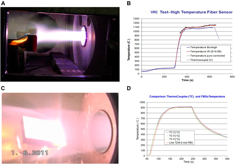
FIGURE 9. (A) Photograph of the Plasma hitting the center of the probe with the FBG (VKI), (B) Comparison of the plasma temperature as measured by the fiber sensors (Burleigh), Thermocouple Pyrometer and IR camera (VKI), (C) Picture of the C-SiC plate with the Fibers and Thermocouples during the Wind Tunnel test at DLR (DLR), (D) Temperature measured by one FBG and close by Thermocouples during the Wind Tunnel test (DLR).
The second validation of the fiber sensors was performed in a plasma wind tunnel at DLR (Cologne-Germany), simulating the reentry at 8 Mach number (3.5 km/s) and 1000°C as shown in Figures 9C,D. The device tested was a (C/SiC) tile, 150 mm × 250 mm × 3 mm thick, similar to those installed on SHEFEX series reentry vehicles built by DLR. The tile embedded three fiber lines, each of them containing three 3 sensors, in addition to a dozen of thermocouples that permitted to show the similarity between the transients and plateaus temperatures seen by the Fiber sensors (100 Hz acquisition) and those seen by the thermocouples (10 Hz acquisition).
An important element of developing technology for space is the effort dedicated to evaluating and qualifying components and systems for the space environment. This section details some of the results achieved at component and system level aimed at improving the Technology Level Readiness of FBG sensor technology for future flight opportunities [30].
Radiation present in space applications has effects on the optical fiber itself, on the FBG elements, and on the optoelectronic components employed on the interrogation units. Several projects along the years have been devoted to investigating these effects and develop radiation tolerant optical sensors and interrogation equipment for space applications. A radiation hardened tunable laser based optical interrogator was developed by OHB and Optics11 FAZ (FAZ Technology) as part of an ARTES project to develop a hybrid sensor bus, designed to be used with FBG sensors inscribed in radiation tolerant fibers as shown in Figure 10A [30]. Different tunable laser control, and signal processing algorithms have been designed and developed to fit within specific available radiation hardened FPGAs to guarantee operation of a single interrogator module providing at least 1 sample per second measurement capability across >20 sensors connected to two separate optical channels. The key optical components including MG-Y tunable laser, optical references (Etalon and Gas Cell), and FBGs were tested for radiation tolerances by emulating the conditions on a geo-stationary satellite including a Total Ionizing Dose (TID) radiation level of up to 100 krad for interrogator components and 25 Mrad for FBGs as shown in Figure 10B [30]. Figure 10C shows the spectral response for all the 100Torr HCN Gas Cell absorption lines across the C-band, measured with an optical interrogator at different dose rates and a zoomed in view of the spectral response of the absorption lines P Branch 06, P Branch 07, and P Branch 08 as shown in Figure 10D. The Gas cells are precision filters whose absorption lines are determined by molecular energy levels. The absorption lines are constant over temperature, so the gas cell can be used as an absolute reference feedback signal. The results show a maximum change of 0.32 pm for the worst absorption line throughout all the radiation test stages and were within the specifications to guarantee operation in such environment [30].
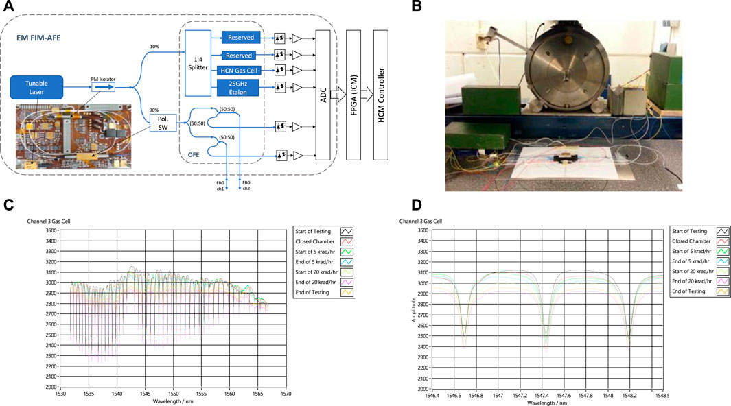
FIGURE 10. (A) CWL shift with 25 Mrad at a dose rate of 420 rad/h, (B) CWL shift at 300 krad total dose (420 rad/h vs. 4.1 rad/h).
A 25 GHz athermal Etalon optical reference was continuously monitored throughout the radiation tests. This optical reference can also be used to detect mode jumps and provide feedback to maintain performance over its designed lifetime of operation on both a component and/or system level. Throughout the Gamma Radiation test any change in the attenuation, a shift in absolute wavelength, change in FSR, or any change in spectral response of the 9 selected Etalon peaks were monitored. The results show that all the spacings between neighboring Etalon peaks remain at 200 pm throughout the test with a standard deviation (Std) of <0.06 pm.
Also, within ESA’s ARTES5.2 and FLPP-Phase 3 projects, Airbus DS and HBM FiberSensing developed a Fiber Bragg Grating (FBG) based monitoring system for thermal mapping in space telecommunication platforms and launchers. The key optoelectronic components underwent a pre-qualification campaign, testing OADM filters, PZT tunable filters, wavelength lockers and MEMS based Variable Optical Attenuators. The samples, all commercial off the shelf devices, were submitted to gamma radiation according to ESCC 22900 with a dose rate of 430 rad (Si)/h and intermediate steps at 10, 20, 30, 60 and 100 krad. From all these devices, only the MEMS based VOA failed on radiation after 30 krad, although a rad-hard version of this component also exists.
As for the optical fiber and FBG elements, HBM FiberSensing have also tested femtosecond written FBGs on rad-hard optical fibers up to 10 MGy as part of several contracts with ITER, showing radiation induced attenuation (RIA) under 70 dB/km and wavelength shifts in the order of tenths of pm. Lifetime of sensors has been demonstrated through extensive testing performed to evaluate the technology for even more challenging environments such as those which will be present in the ITER vacuum vessel. Here sensors will be required to withstand an extreme operational environment, which includes 20000 h at 200°C and gamma radiation doses up-to 10 MGy under high vacuum [42] This gives confidence that sensors can be designed to operate and survive in space environments, even long duration space missions and with the placement of fibers outside the satellite structure.
In addition to the above tests, MPBC prepared three kinds of packaging for radiation testing made by a third party [Kayser-Threde GmbH (now OHB)] addressing the stability of the FBGs in equivalent harsh radiation space environment. The tests covered bare FBGs with only 5 μm polyimide coating, medium thickness tube stainless steel (0.83 mm thick), and larger thickness stainless steel tube (1.37 mm thick). The FBGs were submitted to high radiation level (25Mega-rad at 420 krad/h), 250 times larger than the 100 rad commonly requested. The effect on the FBGs was a shift of 200 pm in the Central Wavelength (CWL) as shown in Figure 11A. A second radiation test (250 krad, at 4.1 krad/h) confirmed the CWL shift. For 100 krad the CWL shift is less than 5 pm at the 4.1 krad/h, and less than 10 pm at 420 krad/h as shown in Figure 11B.
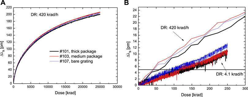
FIGURE 11. (A) CWL shift with 25Mrad at a dose rate of 420rad/h, (B) CWL shift at 300krad total dose (420rad/h vs 4.1rad/h)
Several full systems have been developed by different companies and have undergone full evaluation campaigns as described in the following sections.
To reduce mass, AIT effort, and overall costs of classical point-to-point wired temperature sensor harness on-board a spacecraft, OHB System AG has introduced the Hybrid Sensor Bus (HSB) system which interrogates sensors connected in a bus architecture. To use the advantages of electrical as well as of fiber-optic sensing technologies, the HSB is designed as a modular measurement system interrogating digital sensors connected on electrical sensor buses based on I2C, and fiber-optic sensor buses based on fiber Bragg grating (FBG) sensors inscribed in optical fibers.
HSB has been developed within the ESA ARTES programme with European and German co-funding and was planned to be verified as a flight demonstrator on-board the German Heinrich Hertz satellite (H2Sat). OHB System AG and its predecessor Kayser-Threde GmbH (KTH) established a good knowledge in fiber-optical sensing (FOS) applications for space. With SMAFO and FOSAT KTH demonstrated the applicability of FOS under qualification loads [43].
In its basic configuration HSB consists of four modules which are the: Power Supply Unit (PSU), the HSB Controller Module (HCM), the Interrogator Controller Module (ICM), and the Analog Front End (AFE) for the fiber-optical interrogation as shown in Figure 12A. The ICM handles both the electrical and fiber-optic sensor networks. For the latter it is to be completed by the AFE. On the AFE, a tunable laser is implemented for the scanning of the FBG sensors. The reflected spectra are measured on multiple fiber channels and are then converted to temperatures by use of a peak find algorithm [43]. The Analog Front End incorporates all fiber-optical components and their required control electronics for the interrogation of the fiber-optical sensor networks. The AFE is based on a modulated grating Y-branch (MG-Y) tunable laser. This type of laser diode can be tuned in a wavelength range of 1528–1568 nm. Three currents are required to sweep the laser light over this spectrum to sequentially illuminate all connected FBG sensors. The AFE can be subdivided in to the electronics part and in the Optical Front End (OFE) as shown in Figure 12B. The AFE Electronics consists of six DACs with subsequent voltage-to-current converter circuits to control the MG-Y laser.
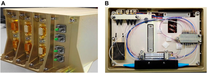
FIGURE 12. (A) Assembled HSB EQM, (B) assembled AFE EQM.
The Optical Front End consists of the fiber-optic components required for the light guidance to the fiber-optic sensor buses by use of passive fiber. An isolator protects the MG-Y laser from back-reflections caused by the FBGs. To handle occurring polarization effects in the fibers, a polarization switch is implemented in the OFE. For every wavelength set by the MGY laser two measurements are performed, each in a polarization state differing by 90° realized by switching the polarization switch. With this, a mean value can be calculated afterwards to mitigate for the birefringence effect on the sensors. The light leaving the polarization switch is then split up into the four fiber-optical channels. On two of these channels FBG arrays can be connected. The other two channels can be used to connect to sensor extension devices to increase the number of fiber-optic sensors interrogated by the HSB. The tunable laser concept allows the distribution of the light to multiple FBG channels for interrogation. Each channel needs then an individual PD with a TIA and ADC for the signal evaluation.
Long term drifts of the M-GY laser’s wavelength mainly caused by radiation are to be compensated for to guarantee stable and accurate operation of the HSB system. For this, an in-orbit recalibration algorithm has been developed by the company Optics11 FAZ (FAZ Technology) who have contributed to the HSB project. The spectra of the fiber-optical reference components are used for the recalibration since they are not affected by long term wavelength drifts. Radiation tests with these components showed that they are not severely affected up to a total ionizing dose of 100 krad, what is calculated to be the highest load inside the HSB Unit for 15 years in a geostationary orbit as shown in Fiber Sensing Component Evaluation. With the information of the reference components the in-orbit recalibration shall be performed on a weekly basis during operation in space.
Within ESA’s ARTES5.2 and FLPP-Phase 3 projects, Airbus DS and HBM FiberSensing developed a Fiber Bragg Grating (FBG) based monitoring system for thermal mapping in space telecommunication platforms and launchers. To integrate FBGs along with other monitoring technologies, the data acquisition unit was designed as a module of Airbus DS’s RTU2015, thus being compatible in both physical dimensions and electrical interfaces aspects, with the Electrical Internal Interface Bus of the Remote Terminal Unit. Within the project a full demonstrator, including sensors, fiber and interrogation electronics, was implemented and characterized up to TRL5 (EM and EQM manufactured and tested) as shown in Figure 13.
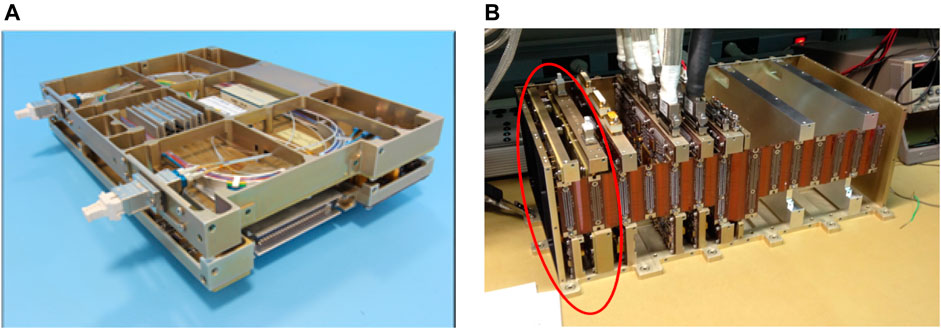
FIGURE 13. (A) FOS Module and (B) pre-integration on Airbus DS RTU2015.
The interrogation unit concept is based on a fiber tunable laser, which continuously sweeps its emission wavelength from 1500 to 1600 nm. The laser light is divided to up to six different fiber channels, which are then individually detected on reflection.
The equipment has multiple redundant optical channels (up to 6), enabling the simultaneous addressing of up-to 120 sensors at 10 Samples/s. Although designed as a module, it is easily adaptable to other host units since it requires just an unregulated 28 V supply and a SPI connection. The module’s weight is 1.2 kg, and dimension is 160 × 233.5 × 52 mm, and has a power consumption under 12.3 W. Each channel includes independent protection against single failure of the associated fiber.
As already described in the previous section, COTS optoelectronic components (Semiconductor Optical Amplifiers, Tunable Filters, Wavelength Lockers, Variable Optical Attenuators and Wavelength Multiplexing Filters) have been employed and they have been validated under radiation in addition to validation testing included Temperature testing (−30°C to +70°C), and vibration (sine, random vibration, and SRS shock tests according to ECSS 10-03 standard) [42, 44, 45].
Over the past few years ESA has supported the in-orbit demonstration of FBG technology on both satellite and launcher platforms. The following section describes three in-orbit demonstrations covering three different applications.
Proba-2 is a small LEO satellite launched by ESA in November 2009, to demonstrate innovative technologies in space. The Fiber Sensor Demonstrator (FSD) on Proba-2, is the first and unique demonstration of a full fiber-optic sensor network in the space environment on a satellite. MPB Communications (MPBC) have developed the FSD as a lightweight fiber-optic sensing system. The system features a central interrogator weighing under 1.3 kg and requiring less than 3.5 W peak power. A single tunable fiber-laser system with integral redundancy is employed to efficiently interrogate a variety of sensor types with approximately 1–2 pm resolution for changes in the sensor wavelength characteristics. This is the first fiber laser in space used to sweep the spectral range and read the intensity at each wavelength between 1520 and 1560 nm. The optoelectronic components and data acquisition board are about 500 g, and the rest (<800 g) is the mass of the protective monolithic aluminium enclosure that must resist the launching mechanical shock and vibrations. The FSD is linked to the Proba-2 via a redundant RS422 link at 115,200 kbps. The FSD system provides six fiber-optic I/O sensor lines and contains sixteen temperature sensors to measure the temperature at different locations in the satellite. Four of these will be linked to provide back-up monitoring for the SSTL propulsion system on Proba-2 and the composite wall around it. This includes separate connectorized fiber-optic signal lines with Diamond FC/APC connectors for the High-Temperature (HT) sensor to measure the transient high temperature in the thruster, up to 450°C, as well as one Pressure/Temperature (P/T) sensor to measure the xenon tank pressure. The first set of on-orbit test data were obtained in January 2010. The FBG lines prepared by MPB follow a classical design, being the first system to be launched in space we looked for proved designs more than innovative ones to reduce the risk and increase their reliability [46, 47].
For the standard measurements of temperature (−50°C to +125°C) around the propulsion tank, the passive fiber was protected by a convenient teflon tube permitting a flexibility in the manipulation and positioning. The FBGs were protected locally by small metallic tube mainly to prevent the effect of strain along the or perpendicular to the fiber, then attached to the tank structure with Al tapes.
The High temperature FBG sensor (up to 400°C) at the Thruster exit needed a special design to respect the minimum acceptable curvature by the fiber (2.5 cm radius) to avoid mechanical and optical issues. The sensor for the pressure at the Xe tank needed to satisfy two requirements. Since the FBG sensor is sensitive to temperature also, two FBGs were involved, the first attached to the structure was sensitive to both temperature and pressure, the second just behind mechanically independent and sensitive only to temperature. The FSD innovative P/T sensor uses multiple FBG gratings with special mounting to provide simultaneous pressure and temperature measurements. The pressure readings are independent of the gas composition. The integral temperature measurements are employed to correct for the effects of temperature on the pressure readings. The P/T sensor employs a heat-treated, orbitally welded stainless steel housing that is suitable for direct contact with propellants such as hydrazine. It can be employed for either single-ended or differential pressure measurements. The P/T sensor was proof tested in N2 at 1200 psi, relative to the maximum operating pressure of 600 psi. The P-sensor response to the applied pressure is very linear with minimal hysteresis comparable to the reference pressure measurement accuracy. This is the first Fiber sensor system on a satellite, it includes also the first fiber laser in space, based on IR erbium doped fibers to sweep over the range 1520–1560 nm and read the FBG CWL value. Figure 14A illustrates the block diagram of the fiber sensor distributions, Figures 14B–C show pictures of the fiber sensor as installed on Proba-2, while Table 3 summarizes their characteristics.
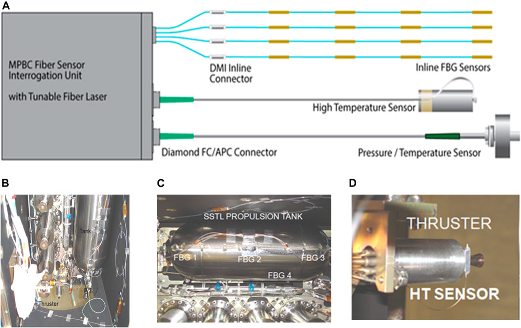
FIGURE 14. (A) Block diagram of the Fiber-optic Sensor Demonstrator for Proba-2, (B–D) Pictures of Fiber Sensors Installed on Proba-2.
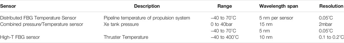
TABLE 3. Summary of the FSD fiber sensors characteristics.
The following figure give examples of the temperature and radiation measured by the FSD system. Figure 15A illustrates the temperature measured, during a heating experiment, by the fiber sensor (FSD-HT) on the thruster’s top along with that measured by the thermocouple (TC) placed at the bottom. The TC presents a lower temperature following the same shape. Figure 15B shows the temperature measured by the 4 sensors and the FBG reference inside the Interrogator box, of a line around the propulsion tank. The data are taken for 300 min i.e., slightly more than 3 cycle orbits. We note that once the system is ON the Interrogator box is slightly heated (about 3°C) and it takes about 1 hr to stabilize, otherwise the temperature is stable, with may be an increase of 0.5°C, in the middle of the orbit cycle as indicated be the FBG reference. Figure 15C shows the evolution of various signals of the FSD components since their on-ground integration (2007-02-09) up to the end of the three orbits cycles measurements in (2018-04-16). The signal showing fluctuations is the box internal temperature AD590_1 thermistor (14°C–32°C) (left Y-axis units). All the other signals refer to the right axis (Volt) with the Y-axis to the right. We can notice, that since the launching, there is a slight increase in the Radfet voltage measuring the global radiation, and a very slight decreasing of the laser diode signal (total <3%).
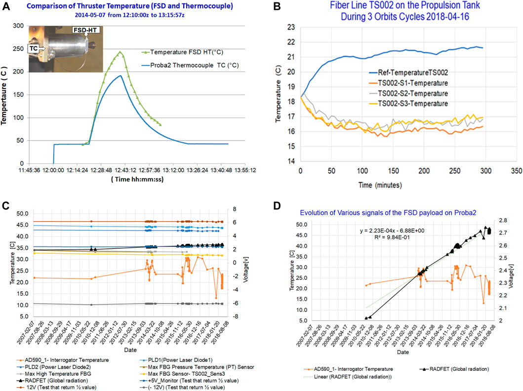
FIGURE 15. (A) Measurement of temperature on Proba2 Thruster during a heating cycle, (B) Temperature of 3 FBGs of Line2 During Three Orbit Cycles 2018-04-16, (C) Evolution of FSD signals since Integration on Proba-2 (2007-02-09 to 2018-04-16), (D) Total Radiation 2009-11-03 to 2018-04-16 (Radfet).
The data downloading failed between 2011 and 2013. In the beginning the FSD software was responding an error message “Failed Communication”. However, the Proba-2 central control unit was showing the system was put ON with 5 V and then turning OFF correctly. After many tests we started to upload and download with simple commands by sending the commands one by one. We verified first that the housekeeping parameters such as voltages, laser diodes, thermistors, were set as requested and responding correctly. Then with these simple commands we tested all the fiber line sensors one by one and confirmed they were responding as when they were integrated on Proba-2. The secured original executable code on the flying processor was downloaded and tested on the FSD Qualification Model Interrogator, it was fully functional. Its copy on the SRAM was failing. The SRAM test showed about 10 wrong bits, they were not responding to our request uploading changes of binary values 0 and 1. Later small code was uploaded to execute various measurements corresponding to the sensor and mode needed (e.g., one acquisition, or many). Other than the 10 lost bits The FSD was completely functional with all its sensors and the modes.
The problem was very probably caused by Single Events Effects (SEE) that hit the SRAM destroying the 10 bits These bits were where the executable software code that was copied on the SRAM, from the saved original copy on the processor. In fact, another payload on Proba-2, the Phoenix-GPS, having 4 SRAM, was affected by the SEE [46]. A Multi-Bit Upset (MBU) rate predicted for 1 event every 40 years on GEO, occurred on one SRAM after less than 1 month of Proba-2 flight. Moreover, a Single Event Burnout (SEB) predicted for 1 event every 300 years for the mission occurred after 1 year of Proba-2. These events are related to the solar cycles show a sudden increase of activity around the end of 2010 up to 2012. These results triggered a SEE study by ESA and DLR with about 120 SRAMs from 4 suppliers, at different Laboratories [47]. The study showed that two very close SRAMs from the same company were affected very differently by the SEE. Figure 15D summarized the results of the radiation deduced from the Radfet measurements and shows with a linear fit between the measurement before the launch (2009-11-03) and during flight up to (2018-04-16). The average is 0.91 krad/year, an indication of higher radiation in the beginning of Proba-2 mission.
The Fiber sensors are reliable sensors for space missions. Having a manual command (bootloader) permitted to identify and solve some catastrophic Single Events. Even after 10 years all the components of FSD are working, the measurements demonstrate that during the 10 years, the laser diode power decreased by less than 3%. A work is progressing to correct the Radfet and laser diodes long term response by deducing the effect of temperature variations between different measurements.
MPB Communications in support of DLR’s Rocket Technology Experiment (ROTEX) developed an FBG system and sensors designed to map the high temperature environment on the outer skin of the rocket during atmospheric re-entry [48]. Four lines of fibers with 6 FBG sensors on each line were integrated in ROTEX-T rocket as shown in Figure 16A, built by DLR and launched in August 2016. During the rollout to the launch stage, the passive fiber used as extension between the sensors and Interrogator, broke inside the engine. The sensors could not record any temperature, however the interrogator itself worked normally and the telemetry data was received as designed. The ROTEX-T payload part including the interrogator, impacted the ground with a velocity of about 95 m/s. The housing of the interrogator and memory stick box were nearly completely undamaged (some of the mounting feet were slightly deformed). All four fiber optic connectors were still attached as shown in Figure 16B. One was bent with no fiber, the other three had about 1.5 m fiber extension, probably this is where the fibers broke during the rollout. The internal memory card was removed and was completely functional as tested by DLR. The card was still working normally, and the flight data files were downloaded. The reading was correct although no temperatures could be recorded. The telemetry data such as voltage applied, laser diode pump power thermostat sensors were correct.
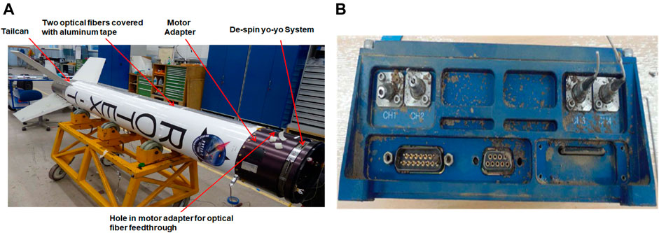
FIGURE 16. (A) Fiber Sensor lines integrated within ROTEX-T structure, (B) Interrogator front with the connectors, three of them having their fibers still attached.
Within the European FP7 PEASSS (Piezoelectric Assisted Smart Satellite Structure) project [49] the application of piezo actuated smart composite panels to improve pointing accuracy and stability of a CubeSat is demonstrated. This technology will be beneficial to all satellite and space instrument platforms. For the PEASSS CubeSat, an FBG based temperature and strain sensor array system including a dedicated interrogator to monitor the critical parts of the smart composite structure are developed by TNO [50]. This resulted in a working 3U CubeSat which was launched with the PSLV mission in the beginning of 2017. The PEASSS FBG sensor system consists of six FBG sensors, four for composite deformation measurement and two for temperature sensing. The four FBG strain sensors are surface mounted on two bimorph actuators. By measuring the response of the FBGs on the top and the bottom of a bimorph actuator simultaneously, change in the bimorph actuator shape can be measured. Two strain isolated FBGs measured the temperature in the CubeSat (FBGTemp_OUT) and inside the interrogator (FBGTemp_IN). Temperature effect and impact of radiation can be canceled out in the deformation measurement. All the FBGs are manufactured in standard single mode fiber which is susceptible to radiation. FBG in radiation hard fiber to suppress the radiation sensitivity can be used in future systems. TNO tested different FBGs manufactured with different laser systems in two types of radiation hard fiber from Draka for nuclear fusion applications [41]. Up to a dose of 4MGy, no clear change in the FBG reflection peak, reflectivity and center wavelength is observed. FBG in comparable fibers are now commercially available.
A special interrogator was designed and built for PEASSS. The interrogator was based on a scanning VCSEL and should be able to interrogate at least 7 FBGs over multiple fibers to enable redundancy in the sensing system. Other optical requirements of the interrogator are: wavelength scanning range of ≥5 nm, wavelength repeatability of ≤12 pm (corresponds to ∼10 µε or ∼1°C), and a measurement frequency of ≥10 Hz. Furthermore, the application requirements for the CubeSat are: Mass ≤800 g, Volume ≤110 mm × 50 mm × 40 mm, and power consumption ≤ 4 W.
The optical power from the scanning VCSEL is divided by a 3 × 3 coupler for the 3 fiber channels. The optical power reflected by the FBGs in each channel is recorded by the corresponding photodiode (PD). While the wavelength during the scanning of the VCSEL is monitored by a 3 × 3 Mach-Zehnder interferometer with a path imbalance. Furthermore, two temperature insensitive FBGs are installed in as wavelength references. The current interrogator is realized with Commercially-off-the-shelf fiber optic components. In the future, the interrogator can be optimized by using VCSEL with a larger scanning range to extend the number of sensors. All the passive fiber optic components can be built on an integrated optics device for further reduction of the size and weight.
The wide spread adoption of FOG technology for rotation measurement in inertial measurement units on-board satellites today clearly demonstrates that there are no fundamental barriers to the more general use of fibre optic sensing for satellite and launcher applications. Despite the advances made in bringing FBG technology into main stream spacecraft engineering, it is clear that the technology still suffers from several important draw backs that need to be overcome for it to find wide spread usage beyond its successful use in rotation measurement. From all the conducted activities, it has been evident that assembly aspects are critical for the successful use of optical fiber sensors in space applications.
With a further development of the fiber-optical sensing technology for space the application of mountings the harness in a classical way as placing the sensors on top of the panels and equipment is seen as more sustainable. This requires a robust harness with transducer-less sensors which can easily mounted without drawbacks in performance.
There are a wide range of fiber cabling solutions that are commercially available, but when providing the optimum choice for fiber cable, there is a required tradeoff between fiber harness protection and cable weight, and the optimum solution will be very dependent on the specific application and the conditions for the fiber routing. As an example of this trade-off, a study conducted by HBM FiberSensing and Airbus DS showed that the use of 700 micron polyimide tubed fiber, weighting 0.32 gr/m, could be employed to substitute the usually employed AWG24 twisted pairs (2.75 gr/m) on applications for thermal control of satellite structural panels, while still providing good mechanical protection. The fibers employed for monitoring the antenna inner layers on the electronic cards for the Electric Propulsion subsystem, as described in previous sections, were on the other hand bare polyimide coated fibers since minimum intrusion was required.
Another key aspect when thinking on cable harnessing is fiber interconnection, especially when several sensors are to be multiplexed into a single fiber to reduce harnessing. Space qualified connectors are available, but they are extremely expensive and prone to failure. The alternative is using fiber splicing all along the fiber chain and leaving fiber connectors only on the interfaces to the final equipment. Although the splicing equipment has evolved from heavy and complex machines into simple handheld devices, splicing on site might not always be an easy approach. As such, the combination of sensors manufactured already in arrays, with onsite fiber splicing only when fiber lengths exceed several meters and having connectors only at the fiber ends has been the optimum approach.
Also, the selection of the fiber-optic cabling is a critical issue due to the impact of the space environment on the optical fiber performance [51].
As an alternative to surface mounting, embedding optical fibers in panels for communication is quoted as effort saving technology where a progressing development can lead to a marketability in a reasonable term. A robust, reliable, and easy to handle interconnection is seen as essential for AIT savings. The Glenair Multi-fiber GFR connector showed good results in the environmental testing and can be proposed as candidate for future applications. Cavities in the panel for communication cables can be implemented during the panel manufacturing without essential losses of stability. The embedding of the fiber with Scotch Weld 2216 showed good performance during the testing. Integration workmanships for the fiber embedding, connectorizing, and testing would be required for product assurance. An investment in tools and training of the AIT personnel is seen as essential for a successful application of fiber-optics for communication embedded in spacecraft panels. For the embedding approach, the potential reduction of stability of the panels caused by the cavities required for the sensor, the inflexibility of positioning of the sensors and the increased time constant are aspects to be further addressed in the future.
On the sensors side, application specific and innovative FBG-based sensor designs with stable calibration, that are ruggedized for the launch vibration levels and extended thermal cycling encountered in the satellite orbit are critical. For strain-temperature discrimination, an approach is the further development of birefringence FBG sensors not using a comparatively heavy transducer.
On the interrogation unit side, the use of COTS vacuum and radiation compatible components is seen as the only viable way forward. Some of available components are military grade and work very well. The remote placement of interrogation system from sensors at an opportune location is vital, and the obsolescence of components is a concern aspect, given the long lifetime cycles associated with space applications. Also standardization on fiber optic sensors, definitions, and test methods is required to improve quality and value. Some effort has already been made in the non-space commercial domain by industry standard bodies (IEC, IEEE, SEAFOM) which could be used as a starting point [52, 53].
Recently an effort to bring fiber optic sensing systems cost down has been demonstrated by using photonic integration. For fiber optic sensors to compete with electrical sensors, several critical parameters of both the sensors and sensor interrogators need to be in place such as performance, cost, size, reliability relevant to the target application. Photonic integrated circuit (PIC) technology enables a reduction in footprint, cost. There exist several PIC technology platforms (e.g., InP, Si, TriPlex) that could be used to develop different optical building blocks used in the interrogator [54] and several companies are developing their interrogators based on such technologies.
In the introduction the topic of distributed sensing was briefly touched on, and it is this approach that might hold the key to the wider exploitation of fiber sensing in space applications. Today distributed sensing technology is more adapted to low spatial resolution over long distances and low measurement bandwidths, however recent advances in processing and increasing performance of opto-electronics are permitting this technology to target higher measurement bandwidths and higher spatial resolutions [55]. The use of standard optical fiber as a sensor without the need for developing specific transducers could have a significant impact on the cost of the fiber optic sensing solution particularly when a large number of sensors are required as might be necessary for the structural health monitoring of large structures such as re-usable rockets or future space habitats.
With the release of bold exploration roadmaps for space tourism and lunar exploitation it is clear that there will be many measurement challenges ahead, and it is our view that fiber optic sensing will be part of the solution.
All authors listed have made a substantial, direct, and intellectual contribution to the work and approved it for publication.
The work described in this paper has been funded predominantly through ESA’s space programmes and European Commissions FP7 program. 2001-Fiber Sensors Smart Integrated Fiber- Optic Sensors for the Satellite Propulsion Subsystems; Contract ESA ESTEC No: 15842/01/NL/LvH. 2003-Proba2: Fiber Sensor Demonstrator (FSD) for Proba 2; Contract ESA ESTEC No: 18601/04/NL/SFe/03/NL/CH. 2007-Re-entry-1 Fiber Optic High Temperature Sensors for Re-entry Vehicle Design and Qualification; Contract ESA ESTEC No: 20873/07/NL/PA. 2011-Re-entry-2; Fiber Optic High Temperature Sensors for Re-entry Vehicle; Contract ESA ESTEC No: 4000104353/11/NL/PA. 2013-ESA-NPI; Mitigation of Small Debris (0.1-10 mm) Effect in Space - Monitored with Fiber Sensors and Self-Repairing Materials - Application to COPVs Contract ESA ESTEC No: 4000109225113/NL/PA. 2015-Canadian Space Agency (CSA): Innovative Versatile Optical Fiber Sensors Suite for Space Applications, CSA, Contract STPD-AO3-MPB, GSTP4: Laser Interrogator for Spacecraft Condition Monitoring (2011-2013), ESA Contract: 4000106145/11/NL/PC, GSTP5.1: Ultra-high sensor count optical interrogator array (2013−2015), ESA Contract: 4000108699/13/NL/PA, FLPP2.2: Avionics and Photonics (2013-2014), ESA Contract: 4000105893.83/.84/.85/.86/.87/.88, ARTES4.2: Hybrid Sensor Bus (HSB) optical sensing for geostationary satellites (2013-2017), ESA Contract: 4000106145/11/NL/PC, GSTP6.2: High precision interrogator for birefringent FBG sensors, for ground testing of satellites (2016-2018), ESTEC Contract: 400011729/16/NL/GLC/fk. Fibre Optic Sensors for Space In-flight Applications. European Space Agency. ARTES 5.2, contract FOS-A-CO-CRS-0003 (9/2012-3/2016). Fiber Optic sensors Telemetry Subsystem-Avionics and Computer Study for FLPP Phase 3. European Space Agency. FLPP PERIOD-2 STEP-2, contract N-4200022863/10/F/IZ, WO-3 (11/2012- 7/2015). Photonics Technologies−Avionics and Computer Study for Future Launcher Preparatory Program. European Space Agency. FLPP PERIOD-2 STEP-1:, contract NGL/FS-ACS-CON-0011 (9/2008 - 10/2010). Fiber Optic Sensing subsystems for Spacecraft Health Monitoring in Telecommunication Satellites. European Space Agency. ARTES 5. contract ESA ITT A0/1-4970/NL/CP (10/2006-10/2008). Hybrid Sensor Bus for Telecommunication Satellites. European Space Agency. ARTES 5.2, contract 4000104262/11/NL/US. Hybrid Sensor Bus auf H2Sat. Deutsches Zentrum für Luft- und Raumfahrt. COMED, contract 50YB1309. Photonically Wired Spacecraft Panels. European Space Agency. EXPRO+, contract 4000111220/14/NL/AD. FP and-SPACE-2012-1 THEME (SPA.2012.2.2-01 SPA.2012.2.2-02)- Key technologies enabling observations in and from space Key technologies for in-space activities, Grant Agreement No. 312216, project PEASSS.
Author SI was employed by the company Optics11 FAZ. Author EH was employed by the company MPB Communications Inc. Author SA was employed by the company HBK FiberSensing. Author AH was employed by the company OHB System AG.
The remaining authors declare that the research was conducted in the absence of any commercial or financial relationships that could be construed as a potential conflict of interest.
All claims expressed in this article are solely those of the authors and do not necessarily represent those of their affiliated organizations, or those of the publisher, the editors and the reviewers. Any product that may be evaluated in this article, or claim that may be made by its manufacturer, is not guaranteed or endorsed by the publisher.
1. Bielas MS, Taylor WT. Progress in Interferometric Fiber Optic Gyroscopes for Space Inertial Reference Units. In: Proceedings of the SPIE Optical Tools for Manufacturing and Advanced Automation 1993; Boston, MA SPIE (1993). 2070. p. 132–141.
2. Mitani S, Mizutani T, Sakai S-i. Current Status of Fiber Optic Gyro Efforts for Space Applications in Japan. In: Proceedings of SPIE Volume 9852, Fiber Optic Sensors and Applications XIII, SPIE Commercial + Scientific Sensing and Imaging; Baltimore, Maryland (2016). 985208. doi:10.1117/12.2229081
3. Girard S, Morana A, Ladaci A, Robin T, Mescia L, Bonnefois J-J, et al. Recent Advances in Radiation-Hardened Fiber-Based Technologies for Space Applications. J Opt (2018) 20:093001. doi:10.1088/2040-8986/aad271
4. Buret T, Ramecourt D, Napolitano F. From Space Qualified Fiber Optic Gyroscope to Generic Fiber Optic Solutions Available for Space Application. In: International Conference on Space Optics, 10566 (2017). SPIE Proc.
5. Lefevre HC, Steib A, Claire A, Sekeriyan A, Couderette A, Pointel AL, et al. The Fiber Optic Gyro ‘Adventure’ at Photonetics, iXsea and Now iXblue. In: SPIE Defense + Commercial Sensing, 2020, Proceedings of SPIE Volume 11405, Optical Waveguide and Laser Sensors (2020) 1140505.
6.Global Fiber Optic Sensor Market Report. Market Research Future (2020). Available at: https://www.marketresearchfuture.com/reports/fiber-optic-sensor-market-2514.
7. Jernej I, Faust M, Lammegger R, McKenzie IA, Kuhnhenn J, Knothe C, et al. Design and Test of the Optical Fiber Assemblies for the Scalar Magnetic Field Sensor Aboard the JUICE Mission. In: International Conference on Space Optics (ICSO); March 31, 2021 (2021). doi:10.1117/12.2600052
8. Riva A, Gai M, Lattanzi MG, Russo F, Buzzi R. BAM: A Metrology Device for a High Precision Astrometric Mission. In: III Workshop on Robotic Autonomous Observatories; Malaga Spain; October 7–11, 2013 (2013).
9. Latka I, Ecke W, Chojetzki C, Reutlinger A. Fiber Optic Sensors for the Monitoring of Cryogenic Spacecraft Tank Structures. Proc SPIE 5579. Phoitonics North 2004. doi:10.1117/12.567353
10. Pinet E. “Pressure Measurement with Fiber-Optic Sensors: Commercial Technologies and Applications”, 21st Internation Conference on Optical Fiber Sensors. Proc SPIE (2011) 7753.
11. Guo Y, Chen M, Xiong L, Zhou X, Li C. Fiber Bragg Grating Acceleration Sensors: A Review. Sensor Rev (2021) 41(1). doi:10.1108/sr-10-2020-0243
12. Jasjot K, Neena Gupta S, Dhawan D. Fiber Bragg Grating Sensors for Monitoring of Physical Parameters: a Comprehensive Review. Opt Eng (2020) 59(6):060901. doi:10.1117/1.oe.59.6.060901
13. Kalli K, Othonos A. Fiber Bragg Gratings: Fundamentals and Applications in Telecommunications and Sensing. Norwood: Artech House (1999).
14. Hill KO, Meltz G. Fiber Bragg Grating Technology Fundamentals and Overview. J Lightwave Technol (1997) 15(Issue 8):1263–76. doi:10.1109/50.618320
16. Lee BH, Kim YH, Park KS, Eom JB, Kim MJ, Rho BS, et al. Interferometric Fiber Optic Sensors. Sensors (2012) 12(3):2467–86. doi:10.3390/s120302467
17. Rao YJ, Jackson DA. Principles of Fiber-Optic Interferometry. In: Grattan KTV, and Meggitt BT, editors. Optical Fiber Sensor Technology. Boston, MA: Springer (2000). doi:10.1007/978-1-4757-6081-1_5
18. Bohnert K, Gabus P, Kostovic J, Brändle H. Optical Fiber Sensors for the Electric Power Industry. Opt Lasers Eng (2005) 43(Issues 3–5):511–26. doi:10.1016/j.optlaseng.2004.02.008
19. Lumens PGE. Fibre-optic Sensing for Application in Oil and Gas wells. [PhD thesis]. Eindhoven: Technische Universiteit Eindhoven (2014). doi:10.6100/IR769555
20. Meng Z, Chen W, Wang J, Hu X, Chen M, Zhang Y. Recent Progress in Fiber-Optic Hydrophones. Photonic Sens (2021) 11:109–22. doi:10.1007/s13320-021-0618-5
21. Poeggel S, Tosi D, Duraibabu D, Leen G, McGrath D, Lewis E, et al. Optical Fibre Pressure Sensors in Medical Applications. Sensors (2015) 15(7):17115–48. doi:10.3390/s150717115
22. Jones JDC. Engineering Applications of Optical Fiber Interferometers. Int Conf InterferometrySPIE Proc (1994) 94:2341.
23. Bahrampour AR, Tofighi S, Bathaee M, Farman F. ISBN:978-953-51-0403-2. In: Ivan Padron D, editor. “Optical Fiber Interferometers and Their Applications – Research Applications in Science and Technology”. Tech (2012).
24. Lu P, Lalam N, Badar M, Liu B, Chorpening BT, Buric MP, et al. Distributed Optical Fiber Sensing: Review and Perspective. Appl Phys Rev (2019) 6:041302. doi:10.1063/1.5113955
25. John Ohanian O, Yakusheva AA, Kreger ST, Kominsky D, Soller BJ, Tran M. Tin Komljenovic, and John E. Bowers, “OFDR on Photonic Circuits: Fiber Optic Sensing Infrastructure and Applications”. In: 26th International Conference on Optical Fiber Sensors (2018).
26. Abad S, Araújo FM, Ferreira LA, Esteban MA, Olea A, Mckenzie I, et al. Thermal Monitoring of Array-Antenna RF Testing Using Fiber Optic Sensors”, 32nd ESA Antenna Workshop. October 5-8, 2010. Noordwijk, Netherlands: ESA ESTEC.
27.Transversal Load Insensitive Optical Waveguide, and Optical Sensor Comprising a Wave Guide, EP2807512(B1).
28. Cheng L-K, Hagen R, Vosteen A, Atli-Veltin B, Peter T, Molkenboer F, Floris van K, van der Togt O. Test Results of Lateral Load Insensitive FBGs Embedded in Composites to Suppress Spectral Distortion. In: Proc. SPIE 10970, Sensors and Smart Structures Technologies for Civil, Mechanical, and Aerospace Systems (2019). p. 109701Y.
29. Pedersen F, Abad S, Araújo FM, Ferreira LA, Karafolas N. Temperature Monitoring in Space Propulsion Systems. In: Space Propulsion Conference 2010; San Sebastian; May 3–6, 2010.
30. Ibrahim SK, Honniball A, McCue R, Todd M, O’Dowd JA, Sheils D, et al. Andreas Hurni, Philipp Putzer, Norbert Lemke, Markus Roner, “Design Challenges of a Tunable Laser Interrogator for Geo-Stationary Communication Satellites”. Int Conf Space Opt (Icso), Paper 153 (2016).
31. Ibrahim SK, McCue R, O’Dowd JA, Farnan M. Design Challenges of a Birefringent FBG Optical Sensing System. In: SPIE Optics +Optoelectronics conference; Prague (2019). Paper 11028-6.
32. Ibrahim SK, McCue R, Dowd JA’O, Farnan M, Karabacak DM. Demonstration of Strain Independent Temperature Measurements Using Optical PM-FBG Sensors for Ground Testing of Satellite Panels. In: International Conference on Space Optics (ICSO 2018), Paper 76; Chania, Greece; October 9–12, 2018, Paper 76 (2018)
33. Ibrahim SK, McCue R, O’Dowd JA, Farnan M, Karabacak DM. Fiber Sensing for Space Applications. In: European Conference on Spacecraft Structures, Materials and Environmental Testing ECSSMET 2018; May 28–June 1, 2018; Noordwijk: ESA-ESTEC (2018).
34. Putzer P, Hurni A, Ziegler B, Panopoulou A, Lemke N, Costa I, Pereira C. Photonically Wired Spacecraft Panels – An Economic Analysis and Demonstrator for Telecommunication Satellites”, In: Proceedings of International Conference on Space Optics (ICSO 2016), Paper 215; Biarritz; October 18–21, 2016 (ICSO 2016), Paper 215.
35. Cheng LK, Ahlers B. Vega Interstate Strain Measurements: Comparison between Conventional Strain Gauges and Fiber Bragg Grating Sensor. In: 6th International Conference on Space Optics; Noordwijk, Netherlands (2006).
36. Cheng LK, van Osnabrugge JC, Groote Schaarsberg JJM. High-Speed Detection System for Fiber Bragg Grating Sensor Array, In: Optro; Paris (2005).
37. Cheng LK, Ahlers B. Vega Interstage Multi-Parameter Measurements Using FBG Sensor Array. In: 18th International Conference on Fiber Optic Sensor; Cancún; October 23–27, 2006 (2006).
38. Siegel M, Gerstmann J, Fischer A, Becker D, Schmidt K, Lindner G, et al. Advanced Sensor Technologies for Cryogenic Liquid Propellant Flow Phenomena. In: 66th International Astronautical Congress; Jerusalem; October 12–16, 2015. IAC-15-C4.5.2.
39. Lupi C, Felli F, Brotzu A, Arturo Caponero M, Paolozzi A. Improving FBG Sensor Sensitivity at Cryogenic Temperature by Metal Coating. IEEE Sensors J (2008) 8(No. 7):1299–304. doi:10.1109/jsen.2008.926943
41. Cheng LK, Vliegenhart W, Habisreuther T. Optical Fiber Grating-Based Technologies and Their Applications: From Medical to Nuclear Fusion. In: Invited paper Photonics Global Conference PGC2012; Singapore (2012).
42. Lima R, Abad S, Monteiro J, Maul J, Ferreira L, Araújo F, Panayotis S, Martin A. High Temperature, High Radiation Strain Sensors and Thermal Compensators for ITER Vacuum Vessel”. In: Proceedings Volume 11199, Seventh European Workshop on Optical Fiber Sensors. Limassol, Cyprus (2019). doi:10.1117/12.2539817
43. Hurni A, Putzer P, Roner M, Gürster M, Hülsemeyer C, Lemke N. Development and Commissioning Results of the Hybrid Sensor Bus Engineering Qualification Model. DASIA 2016-Data Syst Aerospace (2016) 736:48.
44. Ortiz J, Abad S. Fiber Optic Sensors for Space In-Flight Applications. In: ESA satcom final presentation days; Netherlands; 29 January–2 February, 2018.
45. Abad S, Araújo F, Barbero J, González-Torres J, Velasco J, McKenzie I. TESTING OF OPTOELECTRONIC COMPONENTS FOR INTEGRATION INTO SPACE-ORIENTED FIBER BRAGG GRATING MONITORING SYSTEMS. In: International Symposium on Reliability of Optoelectronics for Systems (ISROS 2014). Toulouse: France (2014).
46. D’Alessio M, Poivey C, Ferlet-Cavrois V, et al. SRAMs SEL and SEU In-Flight Data from PROBA-II Spacecraft. In: 14th European Conference on Radiation and Its Effects on Components and Systems (RADECS); Oxford; September 23–27, 2013 RADECS (2013).
47. Cavrois V-Ferlet, Muschitiello M, Alessio M ’D. “Single Event Latch-Up (SEL) Analysis of the 256k X 16 SRAM Samsung K6R4016V1D-TC10 Heavy Ion and Proton Test Report Comparison with the Proba-2 GPS Phoenix SEL Rate”. ESA-Official Documents SEE-Proba2ra0660.pdf
48. Haddad E, Kruzelecky RV, Tagziria K, Aissa B, McKenzie I, Guelhan A, et al. HIGH TEMPERATURE OPTICAL FIBER SENSOR FOR ATMOSPHERIC REENTRY. In: Proceedings of International Conference on Space Optics; Biarritz; October 18–21, 2016 ICSO (2016).
49. Rockberger D, Abramovich H. Piezoelectric Assisted Smart Satellite Structure (PEASS): an Innovative Low Colow-Costsatellite. Proc SPIE (2014) 9057:905714.
50. Toet PM, Maniscalco MP, Hagen RAJ, Hakkesteegt HC, Lugtenburg J. Miniature and Low Cost Fiber Bragg Grating Interrogator for Structural Monitoring in Nano-Satellites. Proc SPIE (2017) 10563:105631E. doi:10.1117/12.2304250
51. Abad S, Araújo FM, Ferreira LA, Pedersen F, Esteban MA, Mckenzie I, Karafolas N. Applications of FBG Sensors on Telecom Satellites. In: International Conference on Space Optics. Rhodes, Greece (2010). October 4 - 8, 2010.
52. Ibrahim SK, Farnan M, Karabacak DM, Singer JM. Enabling Technologies for Fiber Optic Sensing, In: SPIE Photonics Europe 2016; Brussels; April 3–7, 2016. SPIE Photonics Europe (2016). Invited Paper 9899-35, 2016.
53.IEEE 2067-2021 - IEEE Standard for Fiber Optic Sensors–Fiber Bragg Grating Interrogator Standard–Terminology and Definitions. Available at: https://standards.ieee.org/standard/2067-2021.html (Accessed April, 2021).
54. Ibrahim SK, Farnan M, Karabacak DM. Design of a Photonic-Integrated-Based Optical Interrogator. In: SPIE Photonics West 2017 (OPTO-Sensors and Ruggedized Systems I); San Francisco SPIE Photonics West Paper 10110-29 (2017).
Keywords: fiber optic sensing, space, FBG, photonics, sensors, satellites
Citation: McKenzie I, Ibrahim S, Haddad E, Abad S, Hurni A and Cheng LK (2021) Fiber Optic Sensing in Spacecraft Engineering: An Historical Perspective From the European Space Agency. Front. Phys. 9:719441. doi: 10.3389/fphy.2021.719441
Received: 02 June 2021; Accepted: 23 August 2021;
Published: 15 November 2021.
Edited by:
Caterina Ciminelli, Politecnico di Bari, ItalyReviewed by:
Yilin Sun, Beijing Institute of Technology, ChinaCopyright © 2021 McKenzie, Ibrahim, Haddad, Abad, Hurni and Cheng. This is an open-access article distributed under the terms of the Creative Commons Attribution License (CC BY). The use, distribution or reproduction in other forums is permitted, provided the original author(s) and the copyright owner(s) are credited and that the original publication in this journal is cited, in accordance with accepted academic practice. No use, distribution or reproduction is permitted which does not comply with these terms.
*Correspondence: Iain McKenzie, aWFpbi5tY2tlbnppZUBlc2EuaW50
Disclaimer: All claims expressed in this article are solely those of the authors and do not necessarily represent those of their affiliated organizations, or those of the publisher, the editors and the reviewers. Any product that may be evaluated in this article or claim that may be made by its manufacturer is not guaranteed or endorsed by the publisher.
Research integrity at Frontiers
Learn more about the work of our research integrity team to safeguard the quality of each article we publish.