 Irena Zivkovic
94% of researchers rate our articles as excellent or good
Learn more about the work of our research integrity team to safeguard the quality of each article we publish.
Find out more
MINI REVIEW article
Front. Phys., 27 October 2021
Sec. Medical Physics and Imaging
Volume 9 - 2021 | https://doi.org/10.3389/fphy.2021.717369
This article is part of the Research TopicInnovations in MR Hardware from Ultra-Low to Ultra-High FieldView all 14 articles
Moving to the ultrahigh field magnetic resonance imaging (UHF MRI) brought many benefits such as potentially higher signal-to-noise ratio, contrast-to-noise ratio, and improved spectral resolution. The UHF MRI regime also introduced some challenges which could prevent full exploitation of mentioned advantages. A higher static magnetic field means increase in Larmor frequency, which further implies the shorter wavelength in a tissue. The shorter wavelength causes interferences of the RF signal and inhomogeneous excitation, which can be partially resolved by the introduction of the multichannel coil arrays. The biggest problem in UHF multichannel densely populated arrays is the existence of the interelement coupling, which should be minimized as much as possible. This article presents the nonconventional, recently developed decoupling techniques used in UHF MRI.
Moving to the ultrahigh field regime brought many benefits such as increased signal-to-noise ratio (SNR), contrast-to-noise ratio (CNR), and spectral resolution [1–8]. With a higher static magnetic field, the Larmor frequency increases and wavelength in a tissue decreases. Shorter wavelength in a tissue causes constructive and destructive interferences which cause inhomogeneous excitation, lower SNR, and even signal voids. Introduction of parallel transmit (pTx) systems with individually controllable amplitudes and phases of each channel helped in solving the interference problems [4, 9–12]. Multichannel arrays allowed homogeneity shimming of the transmit field in a region of interest and accelerated acquisition. Very often, the individual elements in multichannel arrays are closely spaced, and due to the magnetic flux linkage and stray capacitance emanating from the coils, the problem of interelement coupling arises. The coupling manifests as induced voltage across the terminals of input ports of individual elements in the array. This produces an unwanted tertiary magnetic field, and as a result, the corresponding reflection coefficient measured at the input of the coupled terminals shows “mode splitting.” The coupling of more than two coils will produce additional modes in the frequency spectrum which will manifest in both reflection and transmission coefficients. The coupling is a big issue for transmit-only or transmit-and-receive (transcieve) systems because it dramatically reduces the efficiency and influences the shimming capabilities of pTx systems. However, for receive-only coils, the increased coupling increases noise correlations and has an effect on the g-factor.
The most common coil elements in MRI but also at UHF are loop coils. Widely used decoupling techniques of loop elements are partial overlapping [13], preamplifier decoupling [14], and introduction of the inductive [15] and capacitive networks [16, 17] between the elements. In the work in reference [18], it was demonstrated that at 9.4T, it is possible to decouple an eight-channel loop array only by partial overlap of the elements. It is shown that at 9.4T and for a given size of a loop element, there is an optimal overlap which minimizes both resistive and reactive couplings at the same time. Overlapping of loops allows using of loops with increased diameter. Overlapped loops with increased diameters have increased penetration depth compared to the gapped loops. Overlapping also eliminates a signal void present in the gaps of nonoverlapped loops which improves peripheral SNR (which is associated with a greater loop size). On the receive side, overlapped loops have reduced g-factor but only for higher accelerations [18].
Beside loops, other common elements used in UHF multichannel arrays are dipole and monopole antennas, microstrip elements, and recently proposed shielded-coaxial-cable (SCC) coils. Decoupling strategies developed for loop coils do not easily translate to nonlooped elements; thus, some novel techniques have been introduced.
In this review article, the latest developments in interelement decoupling techniques of the mentioned array elements at UHF will be described.
The shielded-coaxial-cable (SCC) coil has recently been proposed for use at UHF [19, 20]. The SCC coil is made of a coaxial cable with the shield interrupted at one point and with the central conductor interrupted at the opposite point of the shield interruption. The SCC coil design is very similar to that of the high impedance coil [21]. The main difference is in the matching circuit; in the high impedance coil [21], there is a parallel inductor across the feed port, while in the SCC coil design [19, 20], there is a parallel capacitor (the matching circuit contains only capacitors). The use of a matching capacitor versus an inductor influences the coupling properties of the coil. The high impedance coil [21] needs preamplifiers for additional decoupling and for that reason is proposed for use as a receive-only element for hand imaging. The SCC coil is a highly decoupled element, and there is no need for any additional decoupling. Multichannel arrays built with SCC coils are shown in Figure 1. The SCC array elements can be used as both transmit and/or receive elements since their decoupling property does not depend on pre-amplifiers or partial overlapping. Those elements are flexible—the coils can be bent, elongated (Figure 1A,C), and overlapped while maintaining the high interelement decoupling without compromising the performance of the coil. A constructed neck array, for example, consists of five SCC elements placed on flexible foam [20] and can conform to different neck sizes without elements being detuned. Likewise, a five-channel array was constructed for hand imaging [19]. SCC elements were attached to the glove. Due to the hand geometry, every SCC element was elongated, and in a final setup, when the glove with the attached SCC elements was placed on a hand, individual elements, besides being elongated, were also partially overlapped. Even in this extreme case, the tuning and matching were not altered. The diameter of the proposed SCC coil was around 10 cm in all presented examples of arrays operating at 7T. That size of the SCC coil seems to be optimal for different imaging regions (knee, head, neck, hand, etc.). The diameter of the SCC coil cannot be arbitrary. It can vary from around 8 to 12 cm for operation at 7T, and there is a need for using techniques for increasing/decreasing the coil diameter. In the work in reference [22], it is proposed to introduce multiple gaps on the shield and/or inner conductor to obtain the desired coil size. Similarly, in the work in reference [23], different combinations of multiple gaps and multiple turns were proposed for optimal operations at different frequencies. Introduction of the multiple gaps influenced the coupling properties of the coil, which in turn introduced the need for partial overlap for further improvement of decoupling [22]. The coupling properties of the coils proposed in the work in reference [23] were not investigated.
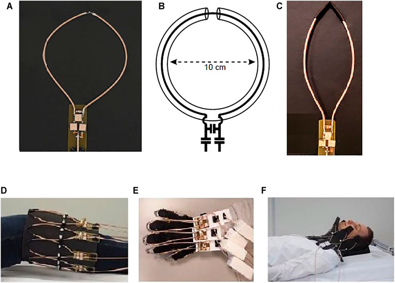
FIGURE 1. Fabricated SCC coils and arrays with SCC coil elements. (A) Round SCC coil, (B) schematics of the SCC element, (C) elongated SCC coil, (D) 8-channel knee array, (E) 5-channel hand array, and (F) 5-channel neck array. This Figure was partially adapted from [19].
Recently the self-decoupled coil principle was introduced, based on the intentional nonuniform distribution of impedances along a rectangular coil [24]. Relatively large impedance is positioned opposite the coil feed port, and the rectangular coil behaves as a hybrid of a dipole and a loop element (Figure 2); thus, the coupling between the adjacent coils is both electric and magnetic in nature (they are of the same magnitude but opposite signs). The current density on a coil’s conductor depends on the impedance of the corresponding arm, and the current’s magnitude defines the coupling nature. The concept can be used for decoupling rectangular coil elements and decoupling between dipoles and loops (Figure 2). The drawback of this method is in the required number of lumped elements, the values of which must be precisely calculated. Also, the relative orientation of the coils with respect to each other is fixed, and therefore is not appropriate for flexible arrays.
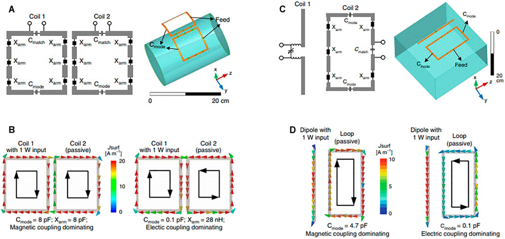
FIGURE 2. (A) Schematics of a pair of decoupled coils. (B) Simulated vector current distribution of magnetic-dominant and electric-dominant coupling. (C) Schematics of a loop–dipole decoupling array. (D) Simulated vector current distribution of a loop-mode and dipole-mode coupling achieved by adjusting the two C-mode capacitors in a loop. This Figure was reproduced from [24].
In the work in reference [25], microstrip elements are ended with meandered structures. It is demonstrated that the size of the meandered structure influences interelement coupling, that is, it is possible to optimize the size and geometry of the meander for the best decoupling between the elements. In the optimized case, no additional decoupling is needed. There are some additional parameters that can be optimized at the same time as the meander size, such as distance between the antennas in the array and the distance from the phantom, for both RF efficiency and coupling properties. After parametric study, it was concluded that the medium meander size produces maximum central H-field strength and optimum decoupling between the elements. This work shows that alteration of the electrical length of the microstrip elements changes current distribution along the element, which influences its coupling properties. Similar strategies can be applied on linear coils such as dipole and monopole antennas.
The use of induced current elimination or magnetic walls has been proposed as a decoupling method for transmission lines [26], loops [27], and monopole [28] and dipole [29, 30] elements. To reduce the mutual coupling, a magnetic wall is inserted between elements in the form of a passive element. The magnetic wall operates as a stopband between the terminals of the coils and eliminates the transmission of energy between the two individual channels. This technique is especially attractive for elements that cannot be partially overlapped or decoupled by using inductive or capacitive networks. In the example of two monopole elements [28], the decoupling element is inserted between the active elements. The decoupling element is a passive monopole element connected through the capacitor to the common ground plane of the two active elements. A similar strategy is also used for loop and microstrip elements [26, 27]. The passive loops and microstrip elements are placed between the two active elements. The electromagnetic field from the active elements induces current into the inserted passive element, and in that way, the coupling between the active elements is reduced. In the work in reference [30], decoupling of two or three active dipoles by insertion of one passive (parasitic) dipole between them has been demonstrated. For a dense array where the distance between the elements is less than one tenth of a wavelength, the decoupling condition differs. This method of decoupling shrinks the operational bandwidth of dipoles. The drawback of this method is in affecting the primary RF field. An additional RF field produced by the inserted passive elements interferes with the primary RF field and reduces the efficiency of the array and/or decreases the primary field homogeneity.
As another example [31], decoupling of meander microstrip line elements with parasitic elements is shown. Conductivity of the sample creates common current paths within the sample, and coupling has resistive (real) and reactive (imaginary) components. The common impedance should be equal to 0 for the completely decoupled case. It must be mentioned that the RF array [31] is surrounded by the RF shield (to be isolated from the gradients and the outside environment), which also has the effect of reducing coupling.
Dipole antennas are very popular antennas at UHF MRI, especially for use as array elements for body imaging. Dipole elements are linear elements, and therefore, decoupling techniques such as geometrical decoupling cannot be applied. There have been several dipole decoupling techniques proposed recently: decoupling with the electromagnetic bandgap (EBG) structures [32], decoupling with stacked resonators [33], and decoupling with metasurfaces [34].
The EBG structures are periodic structures with subwavelength periodicity. The EBG effect prevents all surface modes in a certain frequency band from propagating. In the work in reference [32], the finite EBG structure containing mushroom-type metasurface elements has been designed and positioned between dipole antenna elements. The position of the EBG structure was optimized for the best decoupling between the two elements. With this technique, the interelement decoupling is improved while the biggest drawback is reduced transmit efficiency.
As a decoupling strategy of dipole-type antennas, passive stacked magnetic resonators (SMRs) have been proposed [33]. The design of the SMR structure was inspired by metamaterial structures and consists of several open loops which end with capacitive gaps. Improved decoupling is achieved when more layers are positioned between the coils.
Decoupling of dipole antennas using metasurfaces without distortion of the transmit field has been proposed in the work in reference [34]. The metasurface is a periodic structure which consists of five parallel resonant wires and is a continuation of the work presented in reference [30]. Compared to decoupling with a single resonant wire [29], in the proposed metasurface, it is possible to excite higher-order coupled modes. The single wire acts as a scatterer and produces a strong parasitic resonance. In the work in reference [34], the transmit field of the coil has been studied in the cases without decoupling elements and with one and five resonant decoupling elements. It is shown that adding more resonant elements improves the isolation between the channels without distorting the transmit RF field.
Another decoupling technique applied to dipole and monopole types of antennas is cloaking. In the work in reference [35], the dipole antennas were cloaked with two metasurfaces consisting of N vertical metallic strips. In the work in reference [36], two monopole-type antennas operating at different frequencies were cloaked with two embedded elliptically shaped metasurfaces. The efficiency depends on the number of linear elements in the array, as this constrains the distance between them. For distances less than 1/30th of lambda, the proposed techniques do not work.
Similar to the use of meandered structures at the end of microstrip elements [25] to alter electrical length and current distribution, it is proposed [37] to fold dipole antennas. The eight-element array consisting of folded dipole-type antennas for head imaging has been proposed. It was shown that folding of the dipole element and use of the RF shield close to the folded part can decouple the array elements sufficiently. The mutual inductance is defined by the distance of the dipoles to the RF shield and the length of a folded portion of the dipole element. The optimal decoupling value, S12, can be achieved for various combinations of height and the portion of the folded dipole. The bending and folding of the dipole element “takes away” the current on the element which directly influences coupling between the elements. Different array configurations with different elements were examined, such as bent dipole, straight dipole, 10-mm folded bent dipole, 30-mm folded bent dipole, and 10-mm straight folded dipole. All those arrays were simulated with and without the RF shield. The parameters such as SAR and transmit efficiency and averaged coupling coefficients over all eight elements were observed, and the most optimal array configuration was the one with the 30-mm bent folded dipole.
In this review, we presented the most recent developments in interelement decoupling strategies for application in multichannel array design for operation at UHF MRI. The loop element is one of the most used coils in MRI, but at UHF, other elements, such as dipole and monopole antennas, microstrip coils, and shielded-coaxial-cable coils, were proposed. For newly proposed elements, traditional decoupling techniques cannot be applied. To improve decoupling between the elements at UHF, two strategies could be recognized: 1) use of advanced element design (a shielded-coaxial-cable SCC coil, self-decoupled elements, microstrip elements with a meandered structure at the end, etc.) and 2) development of new decoupling techniques (inclusion of the passive elements, metasurfaces, RF shields, etc.). The advanced element design reduces coupling between the elements by adjusting the geometry and the design concept of the element itself. The shielded-coaxial-cable coil has been proposed as a highly decoupled element, and operation of several arrays at 7T were demonstrated. The optimal coil diameter at 7T is around 10 cm and cannot be increased/decreased arbitrarily. Self-decoupled coils use intentionally nonequal impedance distribution along the coil’s conductor, which defines the current distribution which dictates a coupling between the neighboring elements. The decoupling between the neighboring elements is improved while nonadjacent elements are not solved. The example of a microstrip element terminated by meanders demonstrates the possibility of decoupling between the elements by altering the electrical length of the elements, which further alters the current distribution and influences coupling.
As a second direction in reducing the coupling between the elements in an array is the use of passive structures. The basic principle is the following: the energy that would be transferred between the active elements is captured by the passive element/structure placed close to the active elements. The active elements become isolated from each other. The drawback of this technique is the existence of the secondary RF field produced by the passive element/structure which can reduce the radiation efficiency of the active array. In the work in reference [34], it is shown that the higher number of passive elements and their proper spacing can reduce interaction with the transmit RF field. Passive decoupling structures could also interfere with the receive array elements (in transmit-only receive-only (ToRo) configurations) since the passive elements are not detuned.
Some of the latest developments in the interelement decoupling at UHF were mentioned and discussed. Table 1 summarizes the mentioned coil types and related decoupling methods with the main advantages and disadvantages. There is still room for improvement in designing both elements for the lowest coupling and optimal passive structures to reduce interelement coupling.
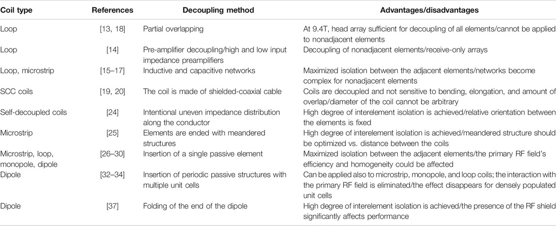
TABLE 1. Summary of the coil type in the array and the decoupling method.
The author confirms being the sole contributor of this work and has approved it for publication.
The author declares that the research was conducted in the absence of any commercial or financial relationships that could be construed as a potential conflict of interest.
All claims expressed in this article are solely those of the authors and do not necessarily represent those of their affiliated organizations, or those of the publisher, the editors, and the reviewers. Any product that may be evaluated in this article, or claim that may be made by its manufacturer, is not guaranteed or endorsed by the publisher.
1. Vaughan JT, Garwood M, Collins CM, Liu W, DelaBarre L, Adriany G, et al. 7T vs. 4T: RF Power, Homogeneity, and Signal-To-Noise Comparison in Head Images. Magn Reson Med (2001) 46:24–30. doi:10.1002/mrm.1156
2. Yacoub E, Shmuel A, Pfeuffer J, Van De Moortele P-F, Adriany G, Andersen P, et al. Imaging Brain Function in Humans at 7 Tesla. Magn Reson Med (2001) 45:588–94. doi:10.1002/mrm.1080
3. Wiggins GC, Potthast A, Triantafyllou C, Wiggins CJ, Wald LL. Eight-channel Phased Array Coil and Detunable TEM Volume Coil for 7 T Brain Imaging. Magn Reson Med (2005) 54:235–40. doi:10.1002/mrm.20547
4. Adriany G, Van de Moortele P-F, Wiesinger F, Moeller S, Strupp JP, Andersen P, et al. Transmit and Receive Transmission Line Arrays for 7 Tesla Parallel Imaging. Magn Reson Med (2005) 53:434–45. doi:10.1002/mrm.20321
5. Ibrahim TS, Mitchell C, Schmalbrock P, Lee R, Chakeres DW. Electromagnetic Perspective on the Operation of RF Coils at 1.5-11.7 Tesla. Magn Reson Med (2005) 54:683–90. doi:10.1002/mrm.20596
6. Zhu X-H, Zhang Y, Tian R-X, Lei H, Zhang N, Zhang X, et al. Development of 17O NMR Approach for Fast Imaging of Cerebral Metabolic Rate of Oxygen in Rat Brain at High Field. Proc Natl Acad Sci (2002) 99:13194–9. doi:10.1073/pnas.202471399
7. Lei H, Zhu X-H, Zhang X-L, Ugurbil K, Chen W. In Vivo31P Magnetic Resonance Spectroscopy of Human Brain at 7 T: An Initial Experience. Magn Reson Med (2003) 49:199–205. doi:10.1002/mrm.10379
8. Zhang X, Ugurbil K, Chen W. Microstrip RF Surface Coil Design for Extremely High-Field MRI and Spectroscopy. Magn Reson Med (2001) 46:443–50. doi:10.1002/mrm.1212
9. Webb A, Collins C. Parallel Transmit and Receive Technology in High‐field Magnetic Resonance Neuroimaging. Int J Imaging Syst Technol (2010) 20:2-13. doi:10.1002/ima.20219
10. Katscher U, Börnert P. Parallel RF Transmission in MRI. NMR Biomed (2006) 19:393–400. doi:10.1002/nbm.1049
11. Abraham R, Ibrahim TS. Proposed Radiofrequency Phased-Array Excitation Scheme for Homogenous and Localized 7-Tesla Whole-Body Imaging Based on Full-Wave Numerical Simulations. Magn Reson Med (2007) 57:235–42. doi:10.1002/mrm.21139
12. Graessl A, Renz W, Hezel F, Dieringer MA, Winter L, Oezerdem C, et al. Modular 32-channel Transceiver Coil Array for Cardiac MRI at 7.0T. Magn Reson Med (2014) 72:276–90. doi:10.1002/mrm.24903
13. Avdievich NI, Giapitzakis IA, Pfrommer A, Shajan G, Scheffler K, Henning A. Decoupling of a Double-Row 16-element Tight-Fit Transceiver Phased Array for Human Whole-Brain Imaging at 9.4 T. NMR Biomed (2018) 31(9):e3964. doi:10.1002/nbm.3964
14. Shajan G, Kozlov M, Hoffmann J, Turner R, Scheffler K, Pohmann R. A 16-channel Dual-Row Transmit Array in Combination with a 31-element Receive Array for Human Brain Imaging at 9.4 T. Magn Reson Med (2014) 71(2):870–9. doi:10.1002/mrm.24726
15. Wu B, Zhang X, Qu P, Shen GX. Design of an Inductively Decoupled Microstrip Array at 9.4T. J Magn Reson (2006) 182:126–32. doi:10.1016/j.jmr.2006.04.013
16. Zhang X, Webb A. Design of a Capacitively Decoupled Transmit/receive NMR Phased Array for High Field Microscopy at 14.1T. J Magn Reson (2004) 170:149–55. doi:10.1016/j.jmr.2004.05.004
17. Lee RF, Giaquinto RO, Hardy CJ. Coupling and Decoupling Theory and its Application to the MRI Phased Array. Magn Reson Med (2002) 48:203–13. doi:10.1002/mrm.10186
18. Avdievich NI, Giapitzakis I-A, Pfrommer A, Henning A. Decoupling of a Tight-Fit Transceiver Phased Array for Human Brain Imaging at 9.4T: Loop Overlapping Rediscovered. Magn Reson Med (2018) 79(2):1200–11. doi:10.1002/mrm.26754
19. Ruytenberg T, Webb A, Zivkovic I. Shielded‐coaxial‐cable Coils as Receive and Transceive Array Elements for 7T Human MRI. Magn Reson Med (2019) 83(3):1135–46. doi:10.1002/mrm.27964
20. Ruytenberg T, Webb A, Zivkovic I. A Flexible Five‐channel Shielded‐coaxial‐cable (SCC) Transceive Neck Coil for High‐resolution Carotid Imaging at 7T. Magn Reson Med (2020) 84(3):1672–7. doi:10.1002/mrm.28215
21. Zhang B, Sodickson DK, Cloos MA. A High-Impedance Detector-Array Glove for Magnetic Resonance Imaging of the Hand. Nat Biomed Eng (2018) 2(8):570–7. doi:10.1038/s41551-018-0233-y
22. Mollaei MSM, Van Leeuwen CC, Raaijmakers AJE, Simovski CR. Analysis of High Impedance Coils Both in Transmission and Reception Regimes. IEEE Access (2020) 8:129754–62. doi:10.1109/access.2020.3009367
23. Nohava L, Czerny R, Roat S, Obermann M, Kuehne A, Frass-Kriegl R, et al. Flexible Multi-Turn Multi-Gap Coaxial RF Coils: Design Concept and Implementation for Magnetic Resonance Imaging at 3 and 7 Tesla. IEEE Trans Med Imaging (2021) 40(4):1267–78. doi:10.1109/tmi.2021.3051390
24. Yan X, Gore JC, Grissom WA. Self-decoupled Radiofrequency Coils for Magnetic Resonance Imaging. Nat Commun (2018) 9:3481. doi:10.1038/s41467-018-05585-8
25. Rietsch SHG, Quick HH, Orzada S. Impact of Different Meander Sizes on the RF Transmit Performance and Coupling of Microstrip Line Elements at 7 T. Med Phys (2015) 42(8):4542–52. doi:10.1118/1.4923177
26. Yan X, Ole Pedersen J, Wei L, Zhang X, Xue R. Multichannel Double-Row Transmission Line Array for Human MR Imaging at Ultrahigh Fields. IEEE Trans Biomed Eng (2015) 62(6):1652–9. doi:10.1109/tbme.2015.2401976
27. Yan X, Zhang X, Feng B, Ma C, Wei L, Xue R. 7T Transmit/Receive Arrays Using ICE Decoupling for Human Head MR Imaging. IEEE Trans Med Imaging (2014) 33(9):1781–7. doi:10.1109/tmi.2014.2313879
28. Yan X, Zhang X, Wei L, Xue R. Magnetic wall Decoupling Method for Monopole Coil Array in Ultrahigh Field MRI: A Feasibility Test. Quant Imaging Med Surg (2014) 4(2):79–86. doi:10.3978/j.issn.2223-4292.2014.04.10
29. Yan X, Zhang X, Wei L, Xue R. Design and Test of Magnetic Wall Decoupling for Dipole Transmit/Receive Array for MR Imaging at the Ultrahigh Field of 7T. Appl Magn Reson (2015) 46:59–66. doi:10.1007/s00723-014-0612-9
30. S.M. Mollaei M, Hurshkainen A, Kurdjumov S, Glybovski S, Simovski C. Passive Electromagnetic Decoupling in an Active Metasurface of Dipoles. Photon Nanostructures - Fundamentals Appl (2018) 32:53–61. doi:10.1016/j.photonics.2018.10.001
31. Abuelhaija A, Orzada S, Solbach K. Parasitic Element Based Decoupling of 7 Tesla MRI Coil Array. In: Loughborough Antennas and Propagation Conference LAPC 2015 (2015).
32. Hurshkainen AA, Derzhavskaya TA, Glybovski SB, Voogt IJ, Melchakova IV, Van Den Berg CAT, et al. Element Decoupling of 7 T Dipole Body Arrays by EBG Metasurface Structures: Experimental Verification. J Magn Reson (2016) 269:87–96. doi:10.1016/j.jmr.2016.05.017
33. Georget E, Luong M, Vignaud A, Giacomini E, Chazel E, Ferrand G, et al. Stacked Magnetic Resonators for MRI RF Coils Decoupling. J Magn Reson (2017) 275:11–8. doi:10.1016/j.jmr.2016.11.012
34. Hurshkainen A, Mollaei MSM, Dubois M, Kurdjumov S, Abdeddaim R, Enoch S, et al. Decoupling of Closely Spaced Dipole Antennas for Ultrahigh Field MRI with Metasurfaces. IEEE Trans Antennas Propagat (2021) 69:1094–106. doi:10.1109/tap.2020.3016495
35. Monti A, Soric J, Alu A, Bilotti F, Toscano A, Vegni L. Overcoming Mutual Blockage between Neighboring Dipole Antennas Using a Low-Profile Patterned Metasurface. Antennas Wirel Propag Lett (2012) 11:1414–7. doi:10.1109/lawp.2012.2229102
36. Moreno G, Yakovlev AB, Bernety HM, Werner DH, Xin H, Monti A, et al. Wideband Elliptical Metasurface Cloaks in Printed Antenna Technology. IEEE Trans Antennas Propagat (2018) 66(7):3512–25. doi:10.1109/tap.2018.2829809
Keywords: decoupling, UHF MRI, RF coils, MRI arrays, interelement decoupling
Citation: Zivkovic I (2021) Interelement Decoupling Strategies at UHF MRI. Front. Phys. 9:717369. doi: 10.3389/fphy.2021.717369
Received: 30 May 2021; Accepted: 24 September 2021;
Published: 27 October 2021.
Edited by:
Roberta Frass-Kriegl, Medical University of Vienna, AustriaReviewed by:
Stephan Orzada, German Cancer Research Center (DKFZ), GermanyCopyright © 2021 Zivkovic. This is an open-access article distributed under the terms of the Creative Commons Attribution License (CC BY). The use, distribution or reproduction in other forums is permitted, provided the original author(s) and the copyright owner(s) are credited and that the original publication in this journal is cited, in accordance with accepted academic practice. No use, distribution or reproduction is permitted which does not comply with these terms.
*Correspondence: Irena Zivkovic, aS56aXZrb3ZpY0B0dWUubmw=
Disclaimer: All claims expressed in this article are solely those of the authors and do not necessarily represent those of their affiliated organizations, or those of the publisher, the editors and the reviewers. Any product that may be evaluated in this article or claim that may be made by its manufacturer is not guaranteed or endorsed by the publisher.
Research integrity at Frontiers
Learn more about the work of our research integrity team to safeguard the quality of each article we publish.