- 1Applied Optics & Spectroscopy Laboratory, Department of Physics, Kumaun University, SSJ Campus, Almora, India
- 2Department of Physics, Soban Singh Jeena (SSJ) University, Almora, India
Mueller–Stokes polarimetry is emerging as a prominent noninvasive imaging technique to study the structural characteristics of an anisotropic medium. Spatial light modulator (SLM) is a programmable liquid crystal device (LCD), which is used to modulate the amplitude, phase, and polarization of light. The compact design and cumbrous manufacturing process of SLM requires its polarimetric calibration prior to its utilization for various applications. In this study, we experimentally demonstrate Mueller–Stokes imaging of a reflective-type SLM (Holoeye, LCR-720) to calibrate its polarization modulation characteristics with respect to its dynamic gray value range (0–255) at different spatial locations of SLM screen. Mueller matrices at 18 different gray values of SLM at an interval of 15, that is, at gray values 0, 15, 30, up to 255 have been experimentally measured using an improvised Mueller matrix imaging polarimeter (MMIP). Crucial polarimetric characteristics, that is, diattenuation, polarizance, state of polarization (SOP), depolarization, and retardance have been estimated with respect to the gray value range of SLM. Significant polarization modulation characteristics [diattenuation (0.08–0.3), polarizance (0.02–0.2), and retardance (0 to
Introduction
Spatial light modulator (SLM) is a programmable optical device, which is used to modulate the amplitude and phase of incident light. SLMs are polarization-sensitive devices and these can modulate SOP of light. Having optimized modulation characteristics, SLMs are the most promising dynamic optical elements in modern imaging applications such as beam shaping [1], digital holography [2], phase-shifting interferometry [3], and biophysics [4]. Most of the SLMs are composed of a systematic alignment of liquid crystal (LC) cells in specific patterns [5]. It permits SLM to utilize the ability of LC cells to align themselves with respect to applied voltage, that is, gray values of SLM. Technically, the required modulation characteristics of light originate from the relative rotation of liquid-crystal (LC) cells about their optical axis within the inner structure of SLM. SLMs are homogeneous optical devices but in practice, most of the commercially available SLMs are not perfectly homogeneous in structure [6, 7]. In fact, the curvature of the cover glass and silicon backplane polishing of SLM may cause a significant nonuniformity in SLM display. Previously reported studies point out that this non-homogeneity in SLM display give rise to a higher light modulation capability at the edges than at the center of SLM display [6]. In addition to limited fill factor, the existence of nonactive area, optical efficiency, and refresh rate of SLM display are other crucial parameters that are responsible for the experimentally observable nonuniformity of SLM [7]. It is noteworthy that this spatial nonuniformity may yield a distorted wave front and irregular modulation characteristics at different spatial parts of SLM display. With limited image array portion of SLM display, it is possible that these factors can generate discrepancies in optimized light modulation characteristics of SLM, especially for the applications where a broader laser beam is required. Therefore, an initial calibration at various spatial locations of the SLM display is required before utilizing it for imaging applications.
Numerous techniques on SLM characterization have been reported in the recent past [5, 8–14]. These techniques can be divided into two main categories, that is, phase characterization techniques [1, 3, 9, 10, 15, 16] and amplitude and intensity characterization techniques [12, 14, 15, 17–19]. SLMs are most effective for their amplitude and phase modulation characteristics and hence most of the calibration methods revolve around phase characterization of SLM. Jones matrix imaging [8, 11, 15], fringe shifting interferometry [3], and phase mask–enabled digital holography [10] are well-known techniques to calibrate the phase modulation characteristics of SLM. However, these techniques are not capable to characterize the intensity modulation and other crucial polarimetric characteristics, that is, diattenuation, polarizance, retardance, and SOP of light after passing through SLM. In addition, intensity and polarization modulation are some of the salient features of SLMs. SLMs are capable of optimizing the polarization characteristics of light as a function of its different gray values. However, the existence of spatial nonuniformity is a major barrier against optimized polarization modulation produced due to SLM.
In order to characterize intensity-based polarization characterization of a sample, several techniques are available, that is, Mueller matrix imaging (MMI) [19, 20], Stokes polarimetry [21], and Poincare sphere [22, 23]. Mueller matrix imaging (MMI) is the most commonly used polarimetric technique in order to characterize the full polarimetric characteristics of a depolarizing medium. MMI is widely used for tissue characterization in biomedical sciences [24, 25], material characterization [26], adulteration detection in samples, [20]etc. In context of SLM characterization using MMI, few studies have been also reported in past [14, 15, 17, 18]. In these studies, SLM is considered as a perfectly homogeneous medium. Recently, Dev et al. reported a study for Mueller–Stokes polarimetric characterization of transmissive-type SLM and calibrated the SLM, considering it as a perfectly homogeneous medium [14]. They captured 36 intensity images for each of 18 gray values of SLM (total 648 intensity images) to determine Mueller matrices for SLM. Further, this study does not depict the polarization modulation at different spatial parts of the SLM display. Apart from this, a study has been reported which focuses on the spatial calibration of SLM display while keeping in mind the manufacturing artifacts of SLM display [7]. In this framework, a pixel-wise phase calibration technique for SLM has been introduced [7]. To the best of the author’s knowledge, no study has been reported on MMI-based spatial characterization of a reflective-type LC-SLM till date.
In this work, we experimentally demonstrate a spatially addressable polarimetric characterization of a reflective-type LC-SLM (Holoeye, LC-R720) using the Mueller–Stokes polarimetric technique. Conventional MMI techniques require 49 intensity images [27] or 36 intensity images [19] at different SOPs of light. These techniques might be suitable for the characterization of samples where only one set of measurement is sufficient, but these are time-consuming for the cases where one needs to take multiple sets of intensity images for detailed characterization of a sample. A comprehensive polarimetric study of SLM requires multiple sets of Mueller intensity images. Therefore, these conventional techniques are somewhere not time-efficient for SLM characterization. In our study, we are able to retrieve Mueller matrices by capturing only 16 intensity images. Hence, this study provides a better time-efficient approach in order to determine Mueller matrices of a sample (SLM) than earlier studies. Mueller matrices of 17 different gray values of SLM (interval of 15) are retrieved by capturing just 288 intensity images. The obtained Mueller images are then analyzed at different spatial locations of SLM display. Further, Lu-Chipman polar decomposition method [28] is applied to obtain polarimetric properties from obtained Mueller matrices. In addition, SOP modulation produced by SLM has also been evaluated and represented in the Poincare sphere.
Materials and Methods
Mueller–Stokes Polarimetry
Mueller matrix of a sample is a transformation matrix of order 4 × 4, which transforms the Stokes parameters (SPs) of incident light (
Experimentally, Mueller matrix of a sample is calculated by using eq. 3, that is, by measuring intensity images at various combinations of six SOPs of light, that is, horizontally polarized (H), vertically polarized (V), +45° polarized (P), −45° polarized (M), right circularly polarized (R), and left circularly polarized (L), respectively.
The SOP rule for polarimetry (eq. 4) transforms eq. 3 into the following:
Polar Decomposition of Mueller Matrices
The polarization properties of sample, that is, diattenuation (D) and polarizance (P) can be directly determined from its Mueller matrix as follows:
The difference in these two polarization properties indicates the depolarizing nature of sample. In order to diagnose further polarization properties, that is, depolarization (
Experimental Measurement of Mueller Matrices
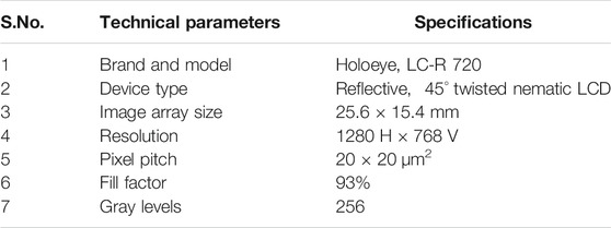
Figure 1 illustrates the schematic of MMIP, which is used for the experimental demonstration of Mueller matrix imaging of a reflective-type LC-SLM (Holoeye, LC-R720). An unpolarized light beam of wavelength 532 nm coming out from a green-diode laser is spatially filtered (SF) and collimated by a convex lens of focal length 20 cm. It is then allowed to pass through an MMIP, which consists of the polarization components, that is, linear polarizers (P1 and P2), quarter-wave plates (Q1 and Q2), a half-wave plate (HWP), and a beam splitter (BS). The technical specifications of the sample (SLM) are summarized in Table 1. Theoretically, MMIP has two arms, that is, the polarization state generator (PSG) and polarization state analyzer (PSA). Four SOPs (H, V, P, and R) are generated in both PSG and PSA arms with the help of polarization components, and corresponding 16 intensity images (different combinations of SOPs) are recorded in the CCD camera (Procilica GX 2750, 2,752 × 2,200 pixels and pixel size of 4.54 μm), placed at the image plane. These images are recorded at a constant frame rate of 10 frames per second (fps) with a fixed exposure time of 0.015 s. A total of 288 intensity images have been recorded for 18 gray values of SLM at the interval of 15 (0, 15, 30, up to 255), respectively, at standard room temperature. Corresponding 18 Mueller matrices have been retrieved from these intensity images using eq. 5.
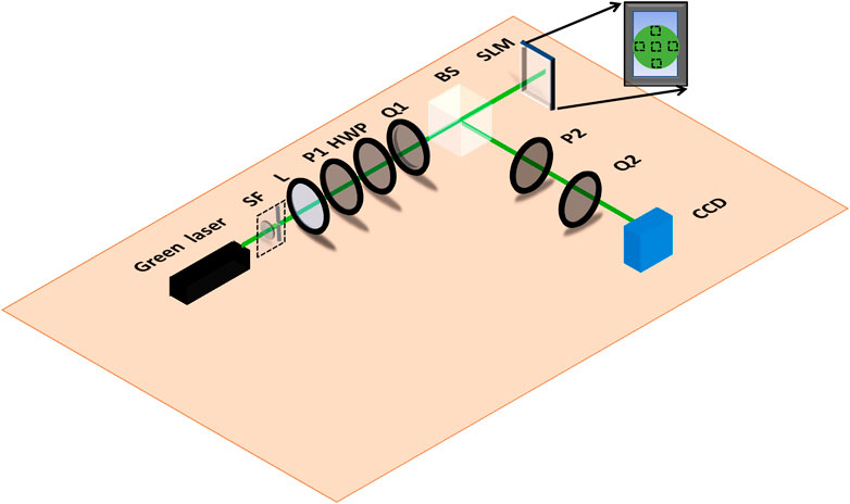
FIGURE 1. Schematic of Mueller matrix imaging polarimeter (MMIP) for Mueller matrix imaging of SLM. [SF: spatial filter, L: lens, P: polarizer, HWP: half-wave plate, Q: quarter-wave plate, BS: beam splitter, SLM: spatial light modulator, CCD: charged coupled device (camera)]. Figure insight represents the selection of spatial locations of SLM display.
To allocate spatial dependency of polarization modulation produced by SLM display, we have selected five-pixel values from different parts, that is, central part (640, 384), right edge (640, 740), left edge (640, 25), upper part (600, 384), and lower part (680, 384) of the light beam over the SLM display. An image window of size 200 × 200 pixels has been cropped around each selected pixel image individually, and these cropped intensity images have been further utilized for corresponding Mueller matrix retrieval. The cropped window size of 200 × 200 is the optimized window size for minimized diffraction effects. Figure 2 is the intensity image IHH at a gray value 255, that is, image formed from the combination of SOP “H” at PSG and SOP “H” at PSA arm of MMIP and corresponding insight represents the 200 × 200 pixel-sized cropped intensity image around the central pixel of CCD. It is equivalent to 45 × 45 pixel-sized cropped intensity image around the central pixel of the SLM.
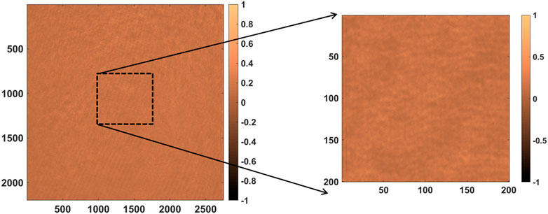
FIGURE 2. Recorded intensity image (IHH) of pixel size 2,200 × 2,752 and its cropped portion (200 × 200 pixels) around central pixel value at gray value 255 of SLM display.
Results and Discussion
Mueller matrix elements as a function of gray values at selected locations of SLM screen are shown in Figure 3. A significant variation in Mueller matrix elements is observed with ascending gray values of SLM. On carefully examining individual Mueller matrix elements at selected locations of SLM screen, it is found that diagonal elements of the Mueller matrix (M22, M33, and M44) are merely uniform over the entire SLM display whereas few Mueller elements (M21, M31, and M41) exhibit fluctuations at the corner (edge) of SLM screen. Moreover, a slight difference between the diattenuation Mueller elements (M12, M13, and M14) and polarizance Mueller elements (M21, M31, and M41) indicates that the SLM exhibits depolarizing nature. Figure 4 provides a more heuristic insight of the variation of Mueller matrix images at three gray values (0, 128, and 255) of SLM at the center (Figures 4A,B,C) and edge (Figures 4D,E,F). On comparing Mueller matrix images at center with Mueller matrix images at the edge of the SLM screen, a noticeable change in Mueller elements is observed. It implies that the SLM yields different polarization response at its different spatial locations. It validates the existence of spatial nonuniformity of polarization modulation for SLM with respect to its gray values. Mueller matrices work as the footprints for polarization properties of the sample (SLM). Therefore, variation of few crucial polarization properties, that is, diattenuation, polarizance, depolarization, retardance, and degree of polarization has been studied by using polar decomposition of obtained Mueller matrices of SLM and represented in Figure 5. On comparing Figures 5A,B, we have observed a slight difference in the variation of diattenuation and polarizance of SLM. It implies that the SLM exhibits a significant amount of depolarizing nature. Moreover, Figure 5C exhibits the existence of depolarization of incident light depending on various gray values of SLM. On the other hand, a phase retardance (0 to
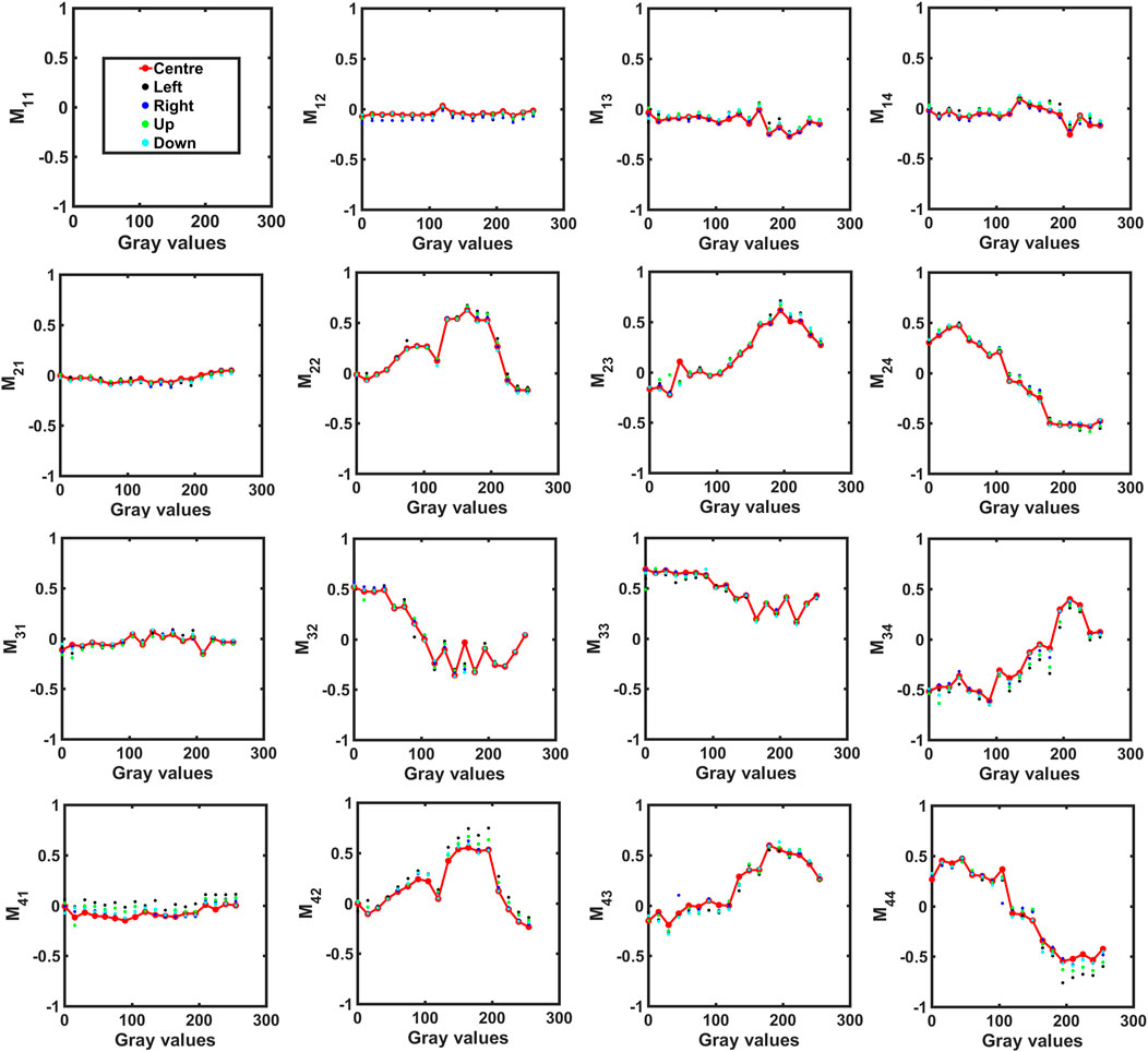
FIGURE 3. Mueller matrix elements as a function of gray values of SLM (Holoeye, LC-R 720) at different spatial locations of the SLM display. Different color dots (red, black, blue, green, and sky-blue) represent the Mueller matrix elements at various spatial locations (center, left edge, right edge, up, and down), respectively. All Mueller matrix elements are normalized with respect to M11.
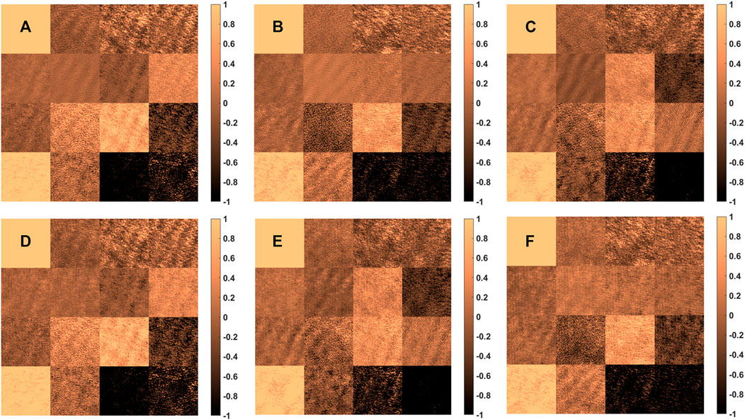
FIGURE 4. Mueller matrix images at three gray values (0, 128, and 255) of SLM at central part of SLM display (A–C) and the left edge of SLM display (D–F), respectively. All Mueller matrix elements are normalized with respect to M11.
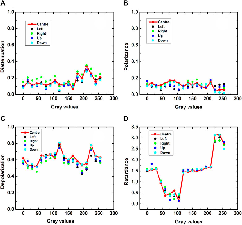
FIGURE 5. Polarization characteristics [(A) diattenuation, (B) polarizance, (C) depolarization, and (D) retardance] of SLM as function of gray values of SLM at different spatial locations [central part (red dots), left edge (black dots), right edge (green dots), up (blue dots), and down (sky-blue dots)] of SLM display. Red colored line represents the polarization characteristics variation in central part of SLM display.
In addition, SOP modulation characteristics from measured Mueller matrices of SLM have been determined using Stokes polarimetry. Figure 6 represents the Poincare sphere representation of SOP modulation trajectories for SLM within the center part (Figures 6A–C) and at the left edge (Figures 6D–F) of SLM display for six SOPs of incident light, respectively. A remarkable SOP modulation is observed with increasing gray values of SLM. On further observing Figures 6A–C, it is evident that SOP modulation trajectories corresponding to incident SOPs “H-polarized,” “45° polarized,” and right circularly polarized light (trajectories with red dots) are exactly the mirror image of the SOP modulation trajectories corresponding to incident SOPs “vertically polarized,” “135° polarized,” and left circularly polarized light (trajectories with blue dots), respectively. On the other hand, Figures 6D–F illustrates the SOP modulation trajectories at edge of SLM display. A comparison of Figures 6A–C with Figures 6D–F reveals that no change in SOP modulation is obtained spatially for SLM display. However, a slight change in DoP is observed at the edge as compared to the central part of SLM display.
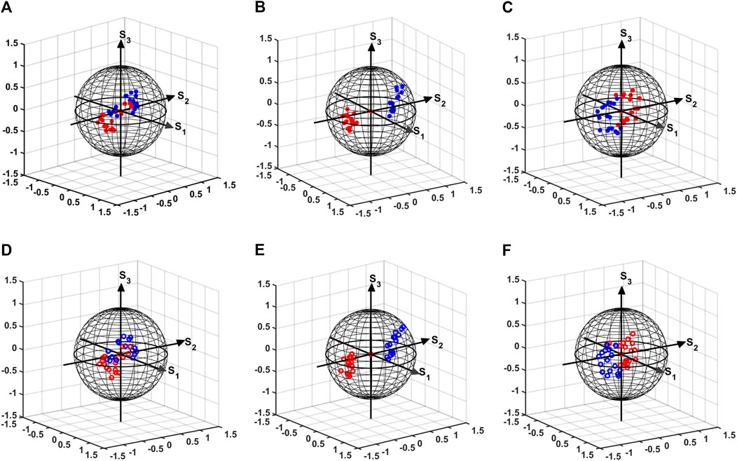
FIGURE 6. Poincare sphere representation of SOP modulation at different gray values of SLM. (A–C): SOP modulation trajectories at central part (D–F): SOP modulation trajectories at the left edge of SLM display. Red dots represent SOP modulation corresponding at incident SOPs “H-polarized,” “45° polarized,” and “right circularly polarized” light and blue dots represent the SOP modulation corresponding to incident SOPs “vertically polarized,” “135° polarized,” and “left circularly polarized” light, respectively.
Conclusion
We have proposed and experimentally demonstrated spatially addressable polarimetric calibration of a reflective-type twisted nematic LC-SLM (Holoeye, LC-R 720) using Mueller–Stokes polarimetric imaging. Mueller matrices at 18 different gray values of SLM at the interval of 15, that is, at gray values 0, 15, 30, up to 255 has been experimentally measured. The obtained Mueller images are analyzed at different spatial locations of SLM display. Crucial polarimetric characteristics, that is, diattenuation, polarizance, SOP modulation, depolarization, and retardance have been estimated with respect to the dynamic gray value range of the SLM. A significant variation polarization modulation characteristics [diattenuation (0.08–0.3), polarizance (0.02–0.2), and retardance (0 to
The obtained results indicate that the Mueller matrices of the SLM exhibit the spatial fluctuations especially at the edges of SLM display. The possible reason of this fluctuation would be the existence of dominant diffractive artifacts at the edges than the central part of the SLM display. Although SOP modulation is not altered at various spatial locations of SLM display, it exhibits spatial variation in DOP of incident light. It is due to the fact that LC molecules are arranged between two glass substrates at twisted nematic (TN) configuration in the SLM, which allows it to modulate both characteristics, that is, the amplitude and phase of incident light. Further results imply that SOP modulation characteristics of SLM yield significant changes with respect to its gray values. The change in gray values of SLM constraints the relative rotation of LC molecules between the glass substrates, and it yields the variation of anisotropic properties with respect to gray values of SLM.
In addition, Mueller matrices are intensity-based measurements, whereas SOP modulation includes phase modulation characteristics of SLM as well. The reason for spatial change in Mueller matrices is that the amplitude modulating characteristics varies at different spatial locations of SLM. However, no spatial change in SOP modulation indicates that phase modulation characteristics remains unchanged with respect to spatial locations of SLM display. Therefore, the SLM shows a significant change in Mueller matrices, whereas no spatial fluctuations in SOP are observed.
In brief, this study depicts the need for spatial polarimetric calibration of SLM display and point out the discrepancies which may arise due to spatial nonuniformity of SLM display. The obtained results recommend that the light beam should be adjusted over only the central part of SLM display for the majority of applications. In addition, the compensation techniques, that is, computational algorithms and phase mask–enabled techniques can be developed to encounter the nonuniformity of the SLM display in edges to enhance the validity of results, where a large beam size is required. We have calibrated the spatial fluctuations in the polarization modulation (Mueller matrices) characteristics of SLM display for a monochromatic light source. However, a wavelength-dependent Mueller metrics characterization of LC-SLM can be performed in future. On the other hand, the image acquisition time (15 ms) may give rise to minor spatial fluctuations due to flicker effects in CCD acquisition as well. Therefore, it is recommended to minimize the flicker effect, while performing similar studies in future. It is expected that the outcomes of this study would be beneficial for various applications of SLM, especially where intensity modulation is a crucial aspect.
Data Availability Statement
The raw data supporting the conclusion of this article will be made available by the authors, without undue reservation.
Author Contributions
VT and NB designed the study. YP has contributed in performing experiment. NB has supervised the study. All authors contributed in article and approved the submitted version.
Conflict of Interest
The authors declare that the research was conducted in the absence of any commercial or financial relationships that could be construed as a potential conflict of interest.
Publisher’s Note
All claims expressed in this article are solely those of the authors and do not necessarily represent those of their affiliated organizations, or those of the publisher, the editors and the reviewers. Any product that may be evaluated in this article, or claim that may be made by its manufacturer, is not guaranteed or endorsed by the publisher.
Acknowledgments
VT would like to acknowledge DST-INSPIRE (IF-170861) and NB acknowledge DST-SERB (YSS/2015/001894) for support to carry out this work.
References
1. Burger L, Litvin I, Ngcobo S, Forbes A. Implementation of a Spatial Light Modulator for Intracavity Beam Shaping. J Opt (2015) 17:015604. doi:10.1088/2040-8978/17/1/015604
2. Rosen J, Kelner R, Kashter Y. (2015). Incoherent Digital Holography with Phase-Only Spatial Light Modulators. J Micro/nanolith MEMS MOEMS p. 14:041307. doi:10.1117/1.jmm.14.4.041307
3. Villalobos-Mendoza B, Granados-Agustín FS, Aguirre-Aguirre D, Cornejo-Rodríguez A. Phase Shifting Interferometry Using a Spatial Light Modulator to Measure Optical Thin Films. Appl Opt (2015) 54:7997. doi:10.1364/ao.54.007997
4. Nikolenko V, Watson BO, Araya R, Woodruff A, Peterka DS, Yuste R. SLM Microscopy: Scanless Two-Photon Imaging and Photostimulation with Spatial Light Modulators. Front Neural Circuits (2008) 2:5. doi:10.3389/neuro.04.005.2008
5. Otón J, Millán MS, Ambs P, Pérez-Cabré E. (2008). Advances in LCoS SLM Characterization for Improved Optical Performance in Image Processing. Proceedings of SPIE 7000, Optical and Digital Image Processing, 70001V, May 6, 2008, doi:10.1117/12.783587
6. Ma´rquez A. Characterization of Edge Effects in Twisted Nematic Liquid crystal Displays. Opt Eng (2000) 39(12):3301. doi:10.1117/1.1321197
7. Veronica C, Elena A, Katkovnik V, Shevkunov I, Egiazarian K. Pixel-Wise Calibration of the Spatial Light Modulator. B. Lee, C. Mazzali, K. Corwin, and R. Jason editors. Frontiers in Optics / Laser Science, OSA Technical Digest. Optical Society of America (2020). doi:10.1364/fio.2020.jtu1b.31
8. Sarkadi T, Koppa P. Measurement of the Jones Matrix of Liquid crystal Displays Using a Common Path Interferometer. J Opt (2011) 13:035404. doi:10.1088/2040-8978/13/3/035404
9. Xia J, Chang C, Chen Z, Zhu Z, Zeng T, Liang P-Y, et al. Pixel-addressable Phase Calibration of Spatial Light Modulators: A Common-Path Phase-Shifting Interferometric Microscopy Approach. J Opt (2017) 19:125701. doi:10.1088/2040-8986/aa8fbc
10. Chandra AD, Banerjee A. Rapid Phase Calibration of a Spatial Light Modulator Using Novel Phase Masks and Optimization of its Efficiency Using an Iterative Algorithm. J Mod Opt (2020) 67:628–37. doi:10.1080/09500340.2020.1760954
11. Tiwari V, Gautam SK, Naik DN, Singh RK, Bisht NS. Characterization of a Spatial Light Modulator Using Polarization-Sensitive Digital Holography. Appl Opt (2020) 59:2024. doi:10.1364/ao.380572
12. Bilgeri LM, Salazar Bloise F, Lu M, Wang S, Jakobi M, Koch AW. Intensity Distortions Due to Phase-Only Spatial Light Modulation: Characterization for Applications in Electronic Speckle-Pattern Interferometry. Rev Scientific Instr (2018) 89:083701. doi:10.1063/1.5029914
13. Wolfe JE, Chipman RA. Polarimetric Characterization of liquid-crystal-on-silicon Panels. Appl Opt (2006) 45:1688. doi:10.1364/AO.45.001688
14. Dev K, Asundi A. Mueller-Stokes Polarimetric Characterization of Transmissive Liquid crystal Spatial Light Modulator. Opt Lasers Eng. (2012) 50. p. 599–607. doi:10.1016/j.optlaseng.2011.10.004
15. Krüger M, Kampmann R, Kleindienst R, Sinzinger S. Time-resolved Combination of the Mueller-Stokes and Jones Calculus for the Optimization of a Twisted-Nematic Spatial-Light Modulator. Appl Opt (2015) 54:4239. doi:10.1364/ao.54.004239
16. Dai Y, Antonello J, Booth MJ. Calibration of a Phase-Only Spatial Light Modulator for Both Phase and Retardance Modulation. Opt Express (2019) 27:17912. doi:10.1364/oe.27.017912
17. Ö P. Investigation of the Optical Properties of the Liquid crystal-based Devices via Mueller Matrix Formalism. Turkish J Phys (2018) 42(4):484-493. doi:10.3906/fiz-1805-4
18. Tiwari V, Bisht NS. Statistical Interpretation of Mueller Matrix Images of Spatial Light Modulator. 2019 Workshop on Recent Advances in Photonics (WRAP); December 13–14, 2019; Guwahati, Assam, India. (2019). 1–3. doi:10.1109/WRAP47485.2019.9013707
19. Márquez A, Moreno I, Iemmi C, Lizana A, Campos J, Yzuel MJ. Mueller-Stokes Characterization and Optimization of a Liquid crystal on Silicon Display Showing Depolarization. Opt Express (2008) 16:1669. doi:10.1364/oe.16.001669
20. Derman D, Şenel EC, Opar E, Ferhanoğlu O, Polat Ö. Optical Characterization of Olive and Sun Flower Oils via Mueller Matrix Polarimetry in Combination with Principal Component Analysis. Food Measure (2021) 15:2309–17. doi:10.1007/s11694-021-00812-1
21. Dahl I. How to Measure the Mueller Matrix of Liquid-crystal Cells. Meas Sci Technol (2001) 12:1938–48. doi:10.1088/0957-0233/12/11/325
22. Durn V, Clemente P, Martínez-León L, Climent V, Lancis J. Poincaré-sphere Representation of Phase-Mostly Twisted Nematic Liquid crystal Spatial Light Modulators. J Opt A Pure Appl Opt (2009) 11(8):085403. doi:10.1088/1464-4258/11/8/085403
23. Durán V, Lancis J, Tajahuerce E, Climent V. Poincaré Sphere Method for Optimizing the Phase Modulation Response of a Twisted Nematic Liquid Crystal Display. J Display Technol (2007) 3:9–14. doi:10.1109/JDT.2006.890710
24. Savenkov SN. Mueller-matrix Characterization of Biological Tissues. M. Mishchenko, Y. Yatskiv, V. Rosenbush, and G. Videen editors. Polarimetric Detection, Characterization and Remote Sensing. NATO Science for Peace and Security Series C: Environmental Security Dordrecht: Springer. (2011) 437–72. doi:10.1007/978-94-007-1636-0_17
25. Ahmad I, Khaliq A, Iqbal M, Khan S. Mueller Matrix Polarimetry for Characterization of Skin Tissue Samples: A Review. Photodiagnosis Photodynamic Ther (2020) 30:101708. doi:10.1016/j.pdpdt.2020.101708
26. Hall SA, Hoyle M-A, Post JS, Hore DK. Combined Stokes Vector and Mueller Matrix Polarimetry for Materials Characterization. Anal Chem (2013) 85:7613–9. doi:10.1021/ac401864g
27. Firdous S. Polarization Sensitive Optical Imaging and Characterization of Soybean Using Stokes-Mueller Matrix Model, Soybean - Genetics And Novel Techniques For Yield Enhancement. D. Krezhova (2011). IntechOpen. doi:10.5772/22705
28. Lu S-Y, Chipman RA. Interpretation of Mueller Matrices Based on Polar Decomposition. J Opt Soc Am A (1996) 13:1106. doi:10.1364/josaa.13.001106
Keywords: Mueller matrix imaging, stokes polarimetry, spatial light modulator, spatial calibration, liquid crystal display
Citation: Tiwari V, Pandey Y and Bisht NS (2021) Spatially Addressable Polarimetric Calibration of Reflective-Type Spatial Light Modulator Using Mueller–Stokes Polarimetry. Front. Phys. 9:709192. doi: 10.3389/fphy.2021.709192
Received: 13 May 2021; Accepted: 05 July 2021;
Published: 12 August 2021.
Edited by:
Hoda A. Ahmed, Taibah University, Saudi ArabiaReviewed by:
Nirmal Mazumder, Manipal Academy of Higher Education, IndiaGeminiano Martinez-Ponce, Centro de Investigaciones en Optica, Mexico
Copyright © 2021 Tiwari, Pandey and Bisht. This is an open-access article distributed under the terms of the Creative Commons Attribution License (CC BY). The use, distribution or reproduction in other forums is permitted, provided the original author(s) and the copyright owner(s) are credited and that the original publication in this journal is cited, in accordance with accepted academic practice. No use, distribution or reproduction is permitted which does not comply with these terms.
*Correspondence: Nandan S. Bisht, YmlzaHQubmFuZGFuQGdtYWlsLmNvbQ==
 Vipin Tiwari
 Yukti Pandey
 Nandan S. Bisht