 Michael Lerond
 Arunprabaharan Subramanian
 W. G. Skene
 Fabio Cicoira
94% of researchers rate our articles as excellent or good
Learn more about the work of our research integrity team to safeguard the quality of each article we publish.
Find out more
ORIGINAL RESEARCH article
Front. Phys. , 24 August 2021
Sec. Interdisciplinary Physics
Volume 9 - 2021 | https://doi.org/10.3389/fphy.2021.708914
This article is part of the Research Topic Organic Electronics: Future Trends in Materials, Fabrication Techniques and Applications View all 5 articles
Stretchable conductors and organic electrochemical transistors (OECT) were fabricated from PEDOT:Tos (poly (3,4-ethylenedioxythiophene):iron tosylate) nanofibers. The devices were prepared by a combination of electrospinning and electrode printing followed by vapor phase polymerization (VPP). The impact of both the processing time and the composition of three electrospinning mixtures on the electrospun fiber mats was evaluated by scanning electron microscopy and cyclic voltammetry. Fibrillar mats prepared from the different mixtures maintained their electrical properties and could be stretched up to 140% of their original length. Stretchable OECTs were fabricated by printing silver drain and source electrodes directly on the conductive spun fibers. The fabricated devices showed transistor behavior up to ∼50% strain.
Interest in plastic electronics has been fuelled by the development of new synthetic methods for preparing conjugated organic materials, that enable organic electronics such as OLEDs, OPVDs, and OFETs [1–3]. Research in this field has further been motivated to bring the intrinsic properties of plastic electronics to fruition. Towards this end, efforts have focused on exploiting the environmental advantages of devices. For example, the efficiency of clean electricity production from sustainable resources using OPVDs continues to improve [4]. Similarly, advances in OLEDs materials result in reduced power consumption and increased efficacy [5].
The virtues of plastic electronics also include their processability. They can be cast from inks using various deposition methods such as spray and sheet coating along with roll-to-roll printing [6, 7]. The advantages of these processing methods is their upscaling with the potential of production-scale device fabrication. These methods of printing conjugated materials that enable plastic electronics can further be applied to a range of substrates that have various mechanical properties. The inks can be applied to rigid and flexible substrates alike, opening the possibility of fabricating conformal devices whereby they can adopt a gamut of shapes and sizes including curved surfaces. This is in contrast with contemporary devices that are fabricated on rigid substrates. Stretchable electronic devices including light-emitting diodes [8], transistors [9] and solar cells [10] have been successfully developed. The virtues of merging flexibility and stretchability into devices give them mechanical properties that are ideally suited for their use in wearable electronics. Indeed, wearable plastic devices have found uses in a range of consumer electronics and healthcare applications.
Stretchable and flexible substrates cannot exclusively render devices wearable. Rather, each component that is integrated into devices must be complementary in their stretchable and bendable behavior. This ensures the layers respond to body motions in concert, resulting in a positive experience by the user when wearing the device. Although the stretchability and flexibility of the device components are critical mechanical properties of wearable electronics, their electrical response must be consistent with applied stress and strain. Given intrinsically conductive electrodes underpin the electrochemical performance of devices, the conductivity of these conjugated organic materials must not be compromised under the typically mechanical stresses and strains that are encountered when wear electronics. Indeed, this remains the principal challenge of the field, despite the many fabrication [11] and performances [12, 13] improvements of stretchable devices.
Poly 3,4 ethylenedioxythiophene (PEDOT), doped with various counterions is ubiquitously used in plastic electronics owing to its high intrinsic conductivity and its processability. Despite these key properties, its rigid conjugated framework limits its capacity to deform. It further suffers from a dramatic loss of electronic conductivity with applied strain and stress. The limited mechanical properties of PEDOT based materials therefore makes it incompatible for use in truly flexible and stretchable devices. Its elongation at break can, however, be improved by blending it with a plasticizer. The plasticizer inserts between the macromolecular chains and it absorbs the external strain [14, 15]. Different fabrication processes have been developed to make the mechanical properties of PEDOT compatible for its use in wearable electronics, while preserving its intrinsic conductivity. Strategies towards this end include depositing on a pre-strained elastomeric substrate [16], the Kirigami method [17, 18], and electrospinning [19–21]. In the latter, non-woven fibers are formed by applying a high voltage bias between a given collecting surface and a polymer solution. The continuous collection of the fibers on the substrate forms a mat consisting of highly entangled fibers. The degree of entanglement and hence the thickness of the mat on the surface depends on the deposition time. The virtue of electrospun coatings is the stretchability of otherwise rigid polymers that is governed by the polymer chain entanglement.
The collective flexibility and stretchability of the electrospun coatings along with the straightforward fabrication make electrospinning an ideal process for preparing stretchable conjugated polymers. Indeed, a range of conjugated polymers have been electrospun including polyaniline [22], P3HT [23], polypyrrole [24, 25] and PEDOT [26–28]. Extensive investigation have correlated the impact of the electrospinning solution viscosity on both the conductivity of the electronpun fiber and the fiber’s morphology [29]. It is further known that the diameter of the electrospun fiber can be modulated by modifying the viscosity of the electrospinning solution [29]. Similarly, the morphology of the fibers can be varied with the use of cosolvents and their orientation can be adjusted by the combination of using different electrodes and varying the applied voltages [30]. Since the morphology of the fibrillar conductive mat significantly impacts its electronic properties, their conductivity can be optimized by adjusting the electrospinning solution.
Despite being a viable method for preparing conductive materials electrospinning is incompatible for directly preparing fibers of PEDOT. This is a result of these conjugated polymers being insoluble in the solvents that are compatible with electrospinning [31]. The spinnability of conjugated polymers can be improved by using carrier polymers such as poly (vinylpyrrolidone) (PVP) [32], poly (vinyl alcohol) (PVA) [33] and poly (ethylene oxide) (PEO) [34]. However, blending these insulating polymers in the electrospinning mixture generally reduces the overall conductivity of the resulting non-woven mat. While electrospun conductive fibers are possible with carrier polymers [19, 20], the correlation between the composition of the electrospinning solution and the resulting conductivity of the electrospun fiber mats remains relatively undefined.
In light of the critical role that PEDOT plays in enabling electronic devices, there is a need to understand the influence of the electrospinning solution composition on the fibers’ conductivity. More importantly, the interplay of the electrospinning mixture composition on the conductivity behavior of PEDOT fibers as a function of fiber stretching and bending needs to be established. This knowledge is of importance for spinning conductive fibers that meet the electronic and mechanical performance requirements for their use in wearable electronic devices. We were therefore motivated to prepare conductive PEDOT:Tos fiber mats by first electrospinning fibers followed by vapor phase polymerization. Three electrospinning mixtures, composed of carrying polymers (PEO and PVP) and varying amounts of oxidant (iron tosylate), along with different spinning times were investigated to understand the effect of electrospinning composition on electronic properties and the stretching behavior of the resulting conductive fibers. To validate the method developed for preparing fibers having suitable conductive and mechanical properties for their use in wearable electronics, the conductive mat was used in a stretchable organic electrochemical transistor (OECT). The conductivity and morphological dependency of PEDOT fibers on the electrospinning mixture composition, their stress/strain dependent conductivity and their use in a proof-of-concept stretchable transistor are herein described.
All reagents and materials were used as received. Polyethylene oxide (PEO) (1 × 10⁶ Da and 5 × 10⁶ Da), imidazole, PVP (1.3 × 10⁶ Da), 3,4-ethylenedioxythiophene (EDOT), ethanol (100%), methylene chloride (DCM), dimethyl sulfoxide (DMSO), activated carbon (Norit, chemically activated), Nafion, isopropanol and the liquid metal gallium–indium eutectic (EGaIn) were purchased from Millipore Sigma. Fe(III) tosylate in butanol (CLEVIOS C-B 54 V3) was purchased from Heraeus Electronic Materials GmbH. Polyethylene terephthalate (PET) sheets (antistatic coating on both sides, thickness ∼175 µm) were purchased from Policrom Inc. (Bensalem, PA, United States). Polydimethylsiloxane (PDMS, SylgardVR 184 Silicone Elastomer kit) was purchased from Dow Corning and processed according to a previously reported method [35]. Glass slides and cloning cylinders were purchased from Corning. Carbon paper (Spectracarb 2050A) was obtained from Fuel Cell Store, United States and the silver ink (Conductor 2, containing metallic silver, ethyl diglycol acetate and mineral salts) from Voltera (Canada).
Three different electrospinning mixtures (A, B and C) were prepared as per below. Before adding CB54 v3, all mixtures were stirred with a magnetic stirrer until the polymer was completed dissolved.
A) A 4 wt% of PEO (400 mg, 1 × 10⁶ Da) was dissolved in DCM (7.22 ml). Afterwards, an aliquot (2.5 g) was mixed with Clevios CB54 v3 (10 g) and imidazole (271 mg).
B) A 9.4 w% PVP (230 mg, 1.3 × 10⁶ Da) solution was prepared by dissolving the polymer in a mixture of EtOH (74 w%, 1.81 g) and DMSO (16.6 w%, 402 mg). Then Clevios CB54 v3 (20.34 g) and imidazole (552 mg) were added to the mixture.
C) As for mixture A, a 4 wt% PEO (400 mg, 5 × 10⁶ Da) solution in DCM (7.22 ml) was prepared. An aliquot (1.5 g) of the solution was mixed with Clevios CB54 v3 (17 g), DCM (4 g), and imidazole (461 mg).
The solutions were stirred with a magnetic stirrer during 10 h at room temperature to ensure the complete dissolution of the polymer carriers (PEO and PVP).
The electrospinning setup includes a RT-collector (Linari Engineering) equipped with a cylindrical collector connected to a high voltage power supply. The electrospinning solution was injected through a 10 ml syringe equipped with a 0.8 mm diameter needle (Linari Engineering) and the injection flux was ensured by a computer-driven pump (Spraybase) at 0.1 ml/h. The relative humidity in the electrospinning hood was maintained between 18 and 23%. All fibers were electrospun at a 10 kV voltage with a distance of 22 cm between the needle and the collector. The collector translation speed was fixed to 20 mm/s and at 500 rpm. The spinning parameters were chosen such that fibers would exclusively be produced without any visible spray and droplets.
The process resulted in a non-woven mat of microfibers composed of the carrying polymer, imidazole, and iron tosylate. Three electrospinning times (700, 1,000 and 1,500 s) were chosen to study the effect of the fiber density on the electronic properties. The fibers were spun on different substrates depending on the required measurement: poly (ethyleneterephtalate) (PET) sheets for sheet resistance and transistors measurements, carbon paper for the electrochemical characterization and poly (dimethylsiloxane) (PDMS) for the stretching tests.
Spin coating was performed with an Ossila Spincoater. The polymer mixtures used for electrospinning were diluted by a factor of two to allow spincoating of thin films (200–300 nm). Homogenous films for conductivity measurements were obtained on 25 mm2 glass slides. For the stretching tests, the films were deposited on PDMS substrates.
The fibers and spin coated films were subsequently transferred to a vapor phase polymerization (VPP) chamber for polymerization.
VPP of EDOT was carried out in a vacuum oven at 45 mBar and 50°C for 24 h. A Petri dish containing EDOT (1 ml) was placed in the lower part of the oven and the samples to polymerize were placed on top. A color change from yellow to light blue confirmed the formation of PEDOT around the fibers and on the spincoated films (Supplementary Figure S1). After VPP, the carrying polymer, unreacted species, and the undesired side products were removed by soaking the polymerized fibers (or films) in a deionized water (DI) bath for 10 min followed by a short rinsing step with EtOH and then water. These are referred to herein as the electrospun fibers (or spincoated films).
Optical images of the fibers were obtained with a Zeiss Imager M1 microscope equipped with an AxioCam MRm camera (Carl Zeiss). Scanning electron microscopy images were obtained after metallization of the samples with gold for 50 s, using a scanning electron microscope fitted with a field emission gun (JEOL JSM7600F). Distributions of the fiber’s diameters were calculated using the software ImageJ, based on SEM pictures. The thickness of the spincoated films was measured with a stylus profilometer (DektakXT Brucker). The sheet resistance was measured with a 4-point probe system (Ossila). The average value of the sheet resistance for each mixture was calculated from five arbitrary chosen regions per sample from five individual samples. Electrochemical measurements were carried out with a potentiostat (Biologic SP 300) and the data were recorded with Ec-lab software. Cyclic voltammetry was performed after bubbling N2 in the electrolyte solution. Potentials were measured relative to an Ag wire that was used as a pseudo-reference electrode in a three-electrode setup with a platinum mesh counter electrode. The working electrodes were electrospun fibers deposited on a 25 mm2 carbon paper. Electrical measurements were performed under ambient conditions with an electrical probe station equipped with a Keysight B2900A source measure unit controlled with a Labview software. The stretchability tests were done with a LabVIEW software-controlled tensile tester.
Organic Electrochemical Transistors (OECTs) were prepared from either electrospun fibers on PET substrates or spincoated films on glass substrates. The fabrication process is schematically represented in Figure 1. Fibers or films were covered with a PET stencil mask for plasma etching to form 12 PEDOT patterns. The PET stencil masks were fabricated using a ScanNcut SDX 1200 Brother cutting machine. The patterns were 2 mm wide and 15 mm long. The samples were etched for 1 h at 100 W and 50 sccm of O2 (Plasmionique FLR 300H). Silver electrodes 11 mm long and 2 mm wide were printed with a Voltera Circuit Printer. The activated carbon gate electrode for aqueous gating medium was prepared using a carbon ink containing activated carbon (28 mg ml−1) and Nafion (1.4 mg ml−1) in isopropyl alcohol. The carbon ink was drop-casted on the carbon paper (Spectracarb 2050) and subsequently heated at 60°C for 5 h to remove solvent traces. The electrode was then confined in a glass cylinder (Φ 7 mm) that was filled with a NaCl solution (0.1 M) as the electrolyte and connected to the gate of the instrument.
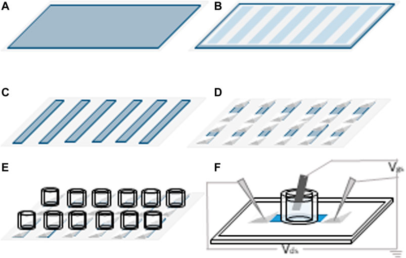
FIGURE 1. Schematic representation of the fabrication process of OECTs. (A) PEDOT:Tos either electrospun or spincoated; (B) PET stencil mask is used to cover the samples and protect unexposed areas; (C) plasma etching is used to remove the unprotected areas; (D) silver source-drain electrodes are printed at both extremities of the patterns; (E) cloning cylinder are used to confine the electrolyte at the center of the device; (F) activated carbon gate electrode is inserted into the glass cylinder and tungsten probes are used to connect source and drain electrodes to the measuring unit.
Stretchable OECTs were prepared as previously reported, using a PDMS substrate [16]. Glass cloning cylinders were replaced by PDMS wells so the gate electrode could sustain the applied strain without breaking. Similarly, the printed silver drain and source electrodes were replaced by EGaIn to further allow the device to be stretched without breaking the contacts.
Fibers were prepared by electrospinning either the PEO or the PVP solutions, as per Table 1. These polymers were chosen because they are ideal carriers for combined electrospinning and vapor phase polymerization of PEDOT [35, 36]. The concentration of the polymers was kept below 1 wt% because a low concentration permits to obtain fibers with a smaller diameter. These were expected to show consistent conductivity with an applied strain. In contrast, fibers with larger diameters were expected to suffer from an undesired decrease in conductivity with applied stress/strain. Clevios CB54-V3 was used as the main component in the mixture to enrich the carrier polymer in the oxidant, thus providing a sufficient number of polymerization sites during VPP. Imidazole was added in a ratio of 0.5% mole relative to the iron tosylate to prevent acidic side-reactions that can arise from the two protons that are formed per degree of polymerization [37]. Two molecular weights of PEO were chosen in part because of their commercial availability. The two chosen molecular weights of PEO are known to form continuous fibers, while being consistent with the molecular weight of the extremely hygroscopic PVP that was also used in the study. The benefit of PEO is that it can be dissolved in minimal amounts of solvent, unlike PVP, resulting in spinning solutions with low viscosities. With the higher molecular weight of PEO, its amount in the electrospinning mixture could be reduced to 0.3 w% without compromising its spinnability. The diameter of the electrospun fibers can be adjusted with the solvent viscosity by varying either the amount of the solvent or the polymer content.

TABLE 1. Composition of the electrospinning mixtures used to prepare fibrillar mats.
The SEM images revealed a difference in the fiber morphology contingent on the electrospinning composition. Qualitative differences in the fibers obtained from the two PEO mixtures are evident in Figures 2A,C). The Mixture B produced homogeneous fibers, whereas those produced from Mixture A are heterogenous. Indeed, both fine needle and bulb-like regions are formed on the same fibers along with the fibers having different thicknesses. Such is the case where multiple fibers of different diameter intersect. The resulting multiple bulb-like crossing points skew the mean average calculated diameter. This aside, randomly orientated fibers that are well-formed on the PET substrate (Figure 2) were observed regardless of the electrospinning mixture.
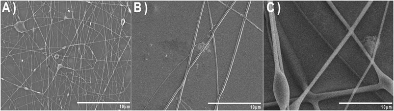
FIGURE 2. SEM pictures of the fibers from the mixtures A (A), B (B) and C (C) after 700 s of electrospinning.
The different molecular weight of the carrying polymer in mixtures A and C led fibers with distinct diameters. The diameter of the as-produced fibers was the largest with the higher molecular weight of PEO in Mixture C. This is a result of its increased intrinsic viscosity relative to Mixture A, according to the Mark-Houwink relationship [38]. The diameter distribution of the fibers produced from Mixture A was bimodal, centered around 300 with a shoulder at 650 nm. In contrast, the diameter distribution from Mixture C had a typical Gaussian distribution with a maximum diameter around 2000 nm (Figure 3). The fibers from mixture B were consistent with those from Mixture A, but with a broader distribution. There was also a difference in the ratio of the two dominant diameter distributions: 2:1 for A and 1:1 for B for the diameters centered at 264 and 616 nm on the one hand and 396 and 748 nm on the other hand.

FIGURE 3. Fiber diameter distribution obtained from SEM images of electrospun mixtures A (A), B (B) and C (C) using 700 s electrospinning time obtained from SEM images.
Considering a conjugated polymer to be a blend of metallic-like grains embedded in a non-conductive and disordered environment, its conductivity is expected to be governed by inter-grain electron transfer. The dense packing, high degree of polymer ordering, and limited defaults of small fibers can collectively promote electron transfer between the metallic-like domains to make small fibers more conductive than large fibers [39]. The electrical properties of the fibers were evaluated in terms of their sheet resistance rather than conductivity. This was because the sample thickness could not be defined. The effect of electrospinning time along with the composition of the spinning mixtures on the fibers’ sheet resistance were evaluated. The sheet resistance was found to decrease with increasing electrospinning time (Table 2). This was expected, due to the higher substrate coverage and the higher number of fiber junctions formed with longer spinning times. There is nearly a twofold decrease in the sheet resistance upon increasing the spinning time from 700 s to 1,000 s, while no improvements were in observed when increasing the spinning time to 1,500 s. This implies the minimum number of junctions that is required to reach the intrinsic conductivity limit of the fibers is formed at 1,000 s. These values are consistent with those reported in the literature for different PEDOT electrospun fibers [28, 40–42]. There was no significant difference in the sheet resistance between the longitudinal and transversal electrospinning direction. Assuming the electronic percolation between the chains at their crossing junction is the transport limiting process in the fibers, the consistent conductivity implies a large number of fiber junctions.
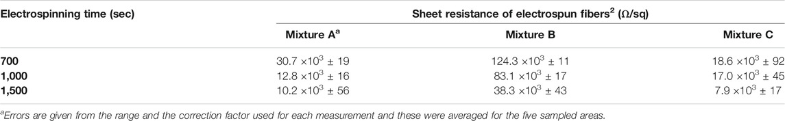
TABLE 2. Sheet resistances of the electrospun randomly oriented fibers non-woven for three different electrospinning times.
While the sheet resistance of fibers obtained from the mixtures A and C were similar, that of fibers obtained from mixture B was remarkably larger. This can in part be attributed to the morphological differences of the fibers. The fibers spun from PEO had fused junctions and they adopted a 2D arrangement, in contrast to the PVP spun fibers that were superimposed. The PVP fibers were stacked and a 3D arrangement was maintained where the fibers intersected. This topology was further expected to enhance the mechanical properties (vide infra).
Conductivity measurements were carried out on samples spincoated from the same mixtures having a similar thickness (ca. 200 nm). As per Table 3, the homogeneously smooth spincoated films have consistent conductivities ranging from ∼200 to ∼250 S cm−1. The measured sheet resistances were similar to those of the fibers electrospun for 1,000 and 15,000 s in the case of the Mixtures A and C. The fibers produced from the Mixture B showed a higher sheet resistance versus the spincoated films. The similar sheet resistance of the spincoated samples indicates that the typical morphology of the fibers from the Mixture B is responsible of the diminution of the conductivity in the fiber mat.
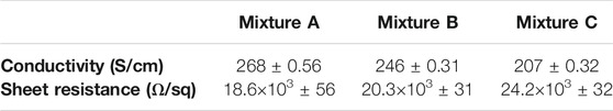
TABLE 3. Conductivities and sheet resistances of films spincoated from the three different mixtures.
The electrospun fibers were further assessed by cyclic voltammetry. This was to evaluate the effect of the spinning time and the polymer carrier on the electrochemical properties of the fibers. More specifically, the quantity of charge transferred with an applied potential, and hence the doping/dedoping capacity of the fiber, can be assessed from the area of a potential vs. current voltammogram. Large areas of the voltammogram are indicative of greater doping/dedoping. Since the spinning time affects the number of fibers that are deposited on the surface along with the number of fiber junctions, the area of the voltammograms depends on the spinning time. The integrated area of the voltammogram for the fibers prepared from the mixture A was indeed greater than the other two mixtures (Figure 4). The relative order of the integrated areas was further consistent with the measured sheet resistance. This confirms the presence of fused fibers and a higher surface area induced by a smaller diameter distribution enhanced conductivity of the electrospun mat.
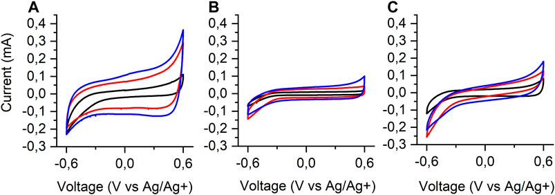
FIGURE 4. Cyclic voltammograms of Mixtures A, B and C in aqueous NaCl (0.1 M) at a scan rate of 20 mV/s for different electrospinning times: 700 (▬), 1,000 (▬) and 1,500 s (▬).
The absence of a well-defined redox process in the cyclic voltammograms confirms the nonexistence of a discrete electron transfer process. It further implies that charge transfer processes take place over a broad range of potentials. This is consistent with a double-layer capacitance in an electrical double layer, common to the three spinning mixtures [43, 44]. Meanwhile, the symmetry of the voltammograms confirms that the fibers can be reversibly doped and undoped with an applied potential with minimal loss of charge. This is a required behavior for use in OECT [45]. The conjugated organic components of OECTs make them suitable for use in both in vivo and in vitro bioelectronics. Similar to other plastic electronics, the mechanical properties of OECTs can be tailored by the judicious choice of the substrate that is used for their fabrication.
A key electrochemical parameter for assessing the suitability of the fibers for used in OECT is their specific capacitance. This can be calculated by integrating the voltammogram, providing the weight of active material is accurately known. Unfortunately, variabilities in the fabrication preclude accurately quantifying the amount of the deposited spun fibers. Given the conductive mats were prepared using similar parameters, the quantity of the fibers deposited for each mixture for the specific electrospinning time is understood to be consistent. The specific capacitance of the fibers prepared from the mixtures A, B, and C were estimated to be about 39, 13 and 25 F/g, respectively (see Supplementary Material). This is possible by comparing the integrated area of the voltammograms of the fibers for the same scan speed. However, the amount of PEDOT:Tos fibers deposited on the carbon paper can be estimated from the electrospinning flow rate, the density of the PEDOT and the surface of the carbon paper used for electrochemical measurements. The specific capacitance of the fibers from the mixture A is greater than the other mixtures. This behavior can be ascribed to two factors. On one hand, there are more fiber junctions for the mixture A compared to the other samples. This results in the fiber’s better overall conductivity and its smaller sheet resistance. On the other hand, the fibers from the mixture A had the smallest diameter relative to the other samples. This affords them a higher specific area and hence a greater electroactive surface area, collectively contributing to its greater capacitance.
Our electrospun fibers were evaluated to see whether they had a consistent conductivity with applied strain. This would make them suitable for stretchable transistors. The stretching of the fibers was assessed by monitoring their current during consecutive stretching cycles. The current as a function of applied strain for the three mixtures and for the three electrospinning times were measured. The fibers obtained from 1,500 s of electrospinning showed the highest current among the three spinning times, consistent with the sheet resistance measurements. All the three samples could undergo at least 80% of strain without significant changes in their sheet resistance. Remarkably, the fibers prepared from Mixture B could be stretched upwards of 140% strain, courtesy of its nodeless morphology. This allows most of the fibers to freely glide upon applied strain without breaking. At this stretching level, the sheet resistance decreased by only ∼15% (Figure 5B). The limited current loss of this sample with strain nonetheless makes it a promising candidate for use in stretchable electronic devices. A similar mixture was previous reported to yield fibers that could be stretched beyond the stretching limit of PDMS (160%), while retaining 15–20% of the initial current [35]. Stretching/releasing cycling tests also showed 50% of the initial current was retained and the current was consistent after only 30 cycles. Also, Shaker et al. reported a high current retention at 40% strain of PEDOT:PSS fibers that were prepared by wet electrospinning on a polyurethane matrix [46].
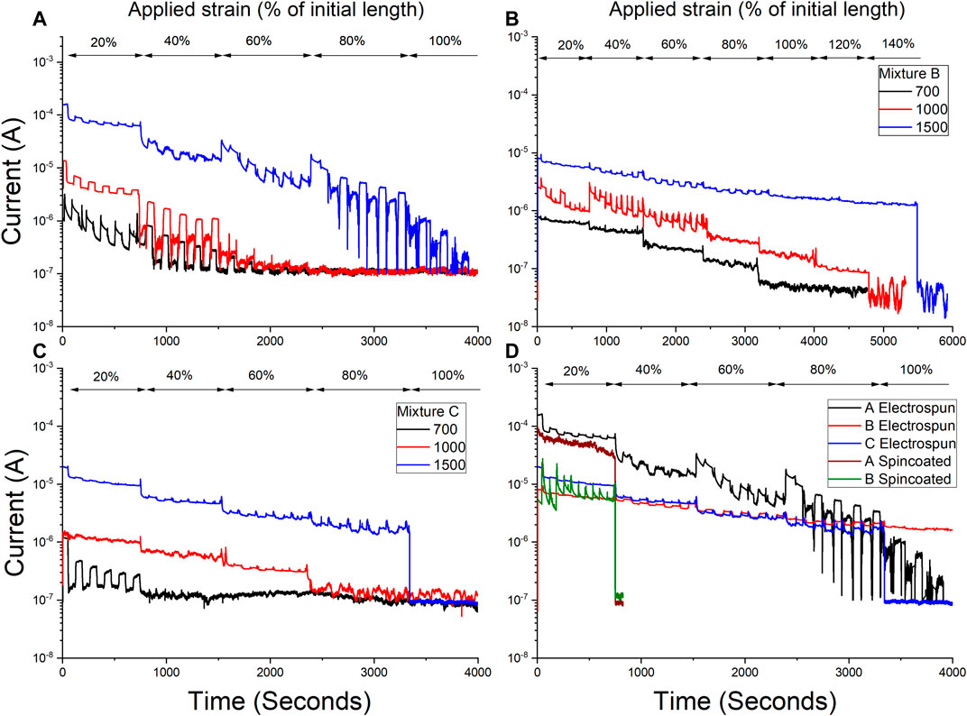
FIGURE 5. Current as a function of time for PEDOT:Tos fibers: Mixtures A (A), B (B) and C (C) on PDMS with different electrospinning times: 700 (▬), 1,000 (▬) and 1,500 s (▬).(D) Current vs time for electrosposun samples: Mixtures A (▬), B (▬) and C (▬) for 1,500 s and spincoated samples on pre-strained PDMS: Mixtures A (▬) and B (▬). The samples were stretched between 20 and 100% strain at 0.1 cm/s. Five consecutive stretching/release cycles were done for each strain between 20 and 100%. The samples were kept in each state (stretched or released) for a resting time of 1 min.
The capacity of the fibers to rearrange and dissipate the strain when stretched were qualitatively evaluated from the pictures that were taken with different applied strains (Supplementary Figure S2A–C). The images show the fibers are progressively damaged (Supplementary Figure S2D–G) when stretched. The onset of the fiber damage for Mixture B occurred at ∼40% strain at which point the fibers lost their linear shape and they curled. No cracks were observed within the fibers from the mixture B, even with ∼120% strain. This is in contrast with the samples that spincoated on PDMS, which cracked at lower applied strains (white clusters Supplementary Figure S2F).
To validate the enhanced stretching capacity of the electrospun samples, their performance was compared to the three mixtures that were spincoated on PDMS. For this, the PDMS was pre-strained to 30% and the samples were then subsequently spincoated [16]. These films adopted a wavy shape when the substrate returned to its normal shape after the applied strain. The spincoated films on PDMS that were not pre-strained broke below 10% strain (Supplementary Figure S3), mainly due to the rigid structure of the PEDOT chains that prevents them from reorganizing and absorbing the strain when stretched. In contrast, the samples that were prepared on pre-strained PDMS could sustain the five stretching cycles at 20% strain but broke at 30% strain, owing to their buckling.
This aside, the PEDOT fibers produced from the three Mixtures could be stretched up to a minimum of 60% strain. The consistent current between the electrospun (1,500 s of electrospinning) and spincoated samples (Figure 5D) confirms that the fiber shape, which is underpinned by the electrospinning process, does not affect the intrinsic electronic properties of PEDOT. The fibers can sustain mechanical deformation under strain because they can reorganize their structure with strain, unlike spincoated films. More importantly, both the mechanical and electronic properties of the final material can be tuned by adjusting the number of fused junctions in a fiber mat.
OECTs were fabricated from both electrospun (Figure 6) and spincoated (Figure 7) samples. The output and transfer characteristics of the as-prepared OECTs showed the typical p-type behavior of PEDOT OECTs operating in depletion mode. Electrospun OECTs prepared from the mixture A showed the best performances. Transistors prepared from spincoated PEDOT showed similar performances to the electrospun fibers, but with higher ON/OFF ratios (∼45). This is consistent with a uniform and similar film morphology that is adopted over the entire surface of the device. In contrast, the fibers adopted unique morphologies that were highly dependent on the composition of the spinning solution and the spinning time. The larger ON/OFF ratios that were observed for the thin spincoated films can be ascribed to the larger contact area of the polymer with the gating medium between the source and the drain terminals compared to the fibers. However, as shown below, the spin coated devices have limited strain performance with respect to fibers.
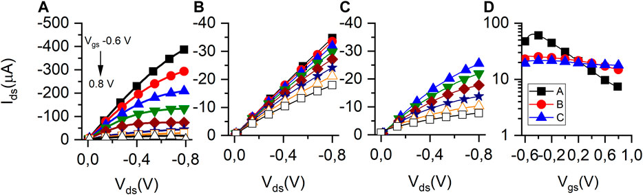
FIGURE 6. Output curves of transistors obtained from mixtures A (A), B (B) and C (C) prepared by 1,500 s electrospinning and an applied gate voltage: 0.6 (■), -0.4 (●), -0.2 (▲), 0 (▼), 0.2 (◆), 0.4 (☆), 0.6 (☐), and 0.8 (△) V, at a sweep rate of 60 s. (D) Transfer curves of transistors of Mixtures A (■), B (●) C (▲) prepared by 1,500 s electrospinning at a VDS of -0.6 V. For visual acuity: the solid lines connect every measured data point and the symbols are drawn at every fifth data point.
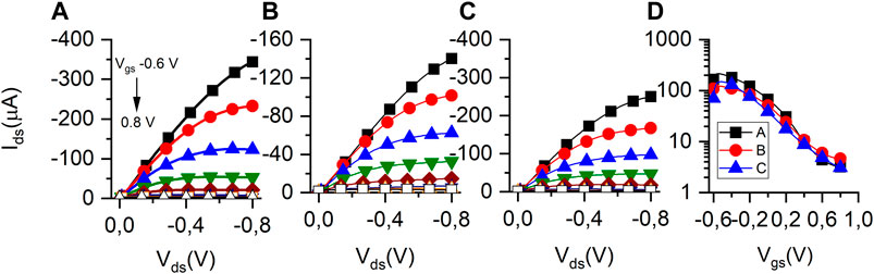
FIGURE 7. Output curves of the transistors of Mixtures A (A), B (B) and C (C) prepared by spincoating and an applied gate voltage: 0.6 (■), -0.4 (●), -0.2 (▲), 0 (▼), 0.2 (◆), 0.4 (☆), 0.6 (☐), and 0.8 (△) V, at a sweep rate of 60 s. (D) Transfer curves of the transistors of Mixtures A (■), B (●) C (▲) prepared by spincoating at a VDS of -0.6 V. For visual acuity: the solid lines connect every measured data point and the symbols are drawn at every fifth data point.
Fibers produced from the mixture B showed the best results during the stretching tests while the ones produced from A led to higher currents, making both of them promising for use in stretchable transistors. Transistors were successively strained in 10% increments and both their transfer characteristics were subsequently recorded (Figure 8).
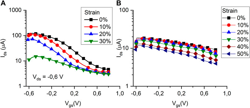
FIGURE 8. Transfer curves of a transistor of Mixtures A (A) and B (B) prepared by electrospinning under different strain: 0% (▬), 10% (▬), 20% (▬), 30% (▬), 40% (▬) and 50% (▬), at a VDS of -0.6 V.
The transistors prepared from the mixture A ceased to work beyond 30% strain, while those from Mixture B functioned up to 50% strain. The OECTs fabricated from Mixture A had ON/OFF ratios that were about 10-fold greater than the devices prepared from Mixture B. Overall, the performance of the transistors prepared from Mixture B was less sensitive to the strain. This is a result of the greater degree of freedom of the fibers and the reduced number of fiber junctions for B relative to A. These distinct features stem from the different fiber morphology that is adopted by the two carrier polymers and from the different density and the number of fused junctions. Indeed, the conductivity of the resulting mat correlates with the number of fused fibers, which in turn, affords more electronic pathways. The tradeoff to this morphology is a reduced elongation at break because the fibers cannot contiguously slide and rearrange without breaking an electronic junction.
Three electrospinning mixtures were prepared to investigate the impact of their composition on the morphology and the electrical properties of the resulting conductive PEDOT:Tos fibers. Conductive fibers were successfully prepared by the vapor phase polymerization of EDOT on the electrospun carrier fibers. The composition of the electrospinning solution and the spinning time led to distinct differences in both the distribution of the diameter and the number of junctions of the conductive fibers. Fibers with a smaller diameter distribution and a greater number of fiber junctions were the most conductive. These fibers also had the greatest specific capacitance owing to their larger specific electroactive area. The electrospun conductive fibers had enhanced stretchable and conductive properties compared to spin coated thin films of PEDOT:Tos. Indeed, the conductivity of the fibers decreased by only 16% when stretched to 140% in length. This is due to their capacity to reorganize their structure with strain. The fibers could also be used in stretchable OECTs. Devices prepared from the fibers acted as OECTs under successive strains from 0 to 50%. Our results illustrate that conductive wires for use in stretchable electronics can be prepared from straightforward methods. By controlling the fiber morphology and their junction density, possible by readily tuning parameters such as polymer carrier and spinning time, stretchable electrodes having consistent conductivities when stretched can potentially be fabricated.
The raw data supporting the conclusions of this article will be made available by the authors, without undue reservation.
ML performed experiments and drafted article. AS helped in performing experiment. FC and WS provided ideas for experiments and finalized the article.
This work is supported by the Defence Research and Development Canada through an IDEaS Micronet (CFPMN1-008) grant awarded to FC.
The authors declare that the research was conducted in the absence of any commercial or financial relationships that could be construed as a potential conflict of interest.
All claims expressed in this article are solely those of the authors and do not necessarily represent those of their affiliated organizations, or those of the publisher, the editors and the reviewers. Any product that may be evaluated in this article, or claim that may be made by its manufacturer, is not guaranteed or endorsed by the publisher.
The Natural Science and Engineering Council Canada (NSERC) is acknowledged for Discovery Grants awarded to FC and WS that enabled this collaborative research. This research is supported by Defence Research and Development Canada through an IDEaS Micronet (CFPMN1-008) grant awarded to FC. Equipment and infrastructure used for this research were acquired and maintained by the Canada Foundation for Innovation and Quebec Strategic Networks (CQMF-QCAM, RQMP, and GCM).
The Supplementary Material for this article can be found online at: https://www.frontiersin.org/articles/10.3389/fphy.2021.708914/full#supplementary-material
1. Wang T, Wang Y-Z, Jing L-C, Zhu Q, Ethiraj AS, Geng W, et al. Novel Biodegradable and Ultra-flexible Transparent Conductive Film for green Light OLED Devices. Carbon (2021) 172:379–89. doi:10.1016/j.carbon.2020.10.027
2. Li Y, He C, Zuo L, Zhao F, Zhan L, Li X, et al. High‐Performance Semi‐Transparent Organic Photovoltaic Devices via Improving Absorbing Selectivity. Adv Energ Mater. (2021) 11:2003408. doi:10.1002/aenm.202003408
3. Hsu L-C, Isono T, Lin Y-C, Kobayashi S, Chiang Y-C, Jiang D-H, et al. Stretchable OFET Memories: Tuning the Morphology and the Charge-Trapping Ability of Conjugated Block Copolymers through Soft Segment Branching. ACS Appl Mater Inter (2021) 13(2):2932–43. doi:10.1021/acsami.0c18820
4. Singh BP, Goyal SK, Kumar P. Solar PV Cell Materials and Technologies: Analyzing the Recent Developments. Mater Today Proc (2021). 43 2843–9. doi:10.1016/j.matpr.2021.01.003
5. Huang Y, Hsiang E-L, Deng M-Y, Wu S-T. Mini-LED, Micro-LED and OLED Displays: Present Status and Future Perspectives. Light: Sci Appl (2020) 9(1):1–16. doi:10.1038/s41377-020-0341-9
6. Wang D, Hauptmann J, May C, Hofstette YJ, Vaynzof Y, Müller T, Roll-to-roll Fabrication of Highly Transparent Ca: Ag Top-Electrode towards Flexible Large-Area OLED Lighting Application. Flexible Printed Electron, (2021). 6, 035001. doi:10.1088/2058-8585/abf159
7. Amruth C, Pahlevani M, Welch GC. Organic Light Emitting Diodes (OLEDs) with Slot-Die Coated Functional Layers. Mater Adv (2021) 2:628–45. doi:10.1039/d0ma00903b
8. Lim MS, Nam M, Choi S, Jeon Y, Son YH, Lee S-M, et al. Two-dimensionally Stretchable Organic Light-Emitting Diode with Elastic Pillar Arrays for Stress Relief. Nano Lett (2020) 20(3):1526–35. doi:10.1021/acs.nanolett.9b03657
9. Oh JY, Rondeau-Gagné S, Chiu Y-C, Chortos A, Lissel F, Wang G-JN, et al. Intrinsically Stretchable and Healable Semiconducting Polymer for Organic Transistors. Nature (2016) 539(7629):411–5. doi:10.1038/nature20102
10. Qin J, Lan L, Chen S, Huang F, Shi H, Chen W, et al. Recent Progress in Flexible and Stretchable Organic Solar Cells. Adv Funct Mater (2020) 30(36):2002529. doi:10.1002/adfm.202002529
11. Lu Y, Gao S, Li F, Zhou Y, Xie Z, Yang H, et al. Stretchable and Twistable Resistive Switching Memory with Information Storage and Computing Functionalities. Adv Mater Technol (2021) 6(1):2000810. doi:10.1002/admt.202000810
12. Hsu L-C, Isono T, Lin Y-C, Kobayashi S, Chiang Y-C, Jiang D-H, et al. Stretchable OFET Memories: Tuning the Morphology and the Charge-Trapping Ability of Conjugated Block Copolymers through Soft Segment Branching. ACS Appl Mater Inter (2021) 13:2932–43. doi:10.1021/acsami.0c18820
13. Chen S, Xie J, Liu J, Huang X, Wang C. Transparent, Highly-Stretchable, Adhesive, and Ionic Conductive Composite Hydrogel for Biomimetic Skin. J Mater Sci (2021) 56(3):2725–37. doi:10.1007/s10853-020-05382-z
14. Li Y, Zhang S, Li X, Unnava VRN, Cicoira F. Highly Stretchable Polystyrene Sulfonate Organic Electrochemical Transistors Achieved via Polyethylene Glycol Addition. Flexible Printed Electron (2019) 4(4):044004. doi:10.1088/2058-8585/ab5202
15. Kayser LV, Lipomi DJ. Stretchable Conductive Polymers and Composites Based on PEDOT and PEDOT:PSS. Adv Mater (2019) 31(10):1806133. doi:10.1002/adma.201806133
16. Zhang S, Hubis E, Tomasello G, Soliveri G, Kumar P, Cicoira F. Patterning of Stretchable Organic Electrochemical Transistors. Chem Mater (2017) 29(7):3126–32. doi:10.1021/acs.chemmater.7b00181
17. Guan Y-S, Li H, Ren F, Ren S. Kirigami-inspired Conducting Polymer Thermoelectrics from Electrostatic Recognition Driven Assembly. ACS nano (2018) 12(8):7967–73. doi:10.1021/acsnano.8b02489
18. Morikawa Y, Yamagiwa S, Sawahata H, Numano R, Koida K, Ishida M, et al. Ultrastretchable Kirigami Bioprobes. Adv Healthc Mater. (2018) 7(3):1701100. doi:10.1002/adhm.201701100
19. Babaie A, Bakhshandeh B, Abedi A, Mohammadnejad J, Shabani I, Ardeshirylajimi A, et al. Synergistic Effects of Conductive PVA/PEDOT Electrospun Scaffolds and Electrical Stimulation for More Effective Neural Tissue Engineering. Eur Polym J (2020) 140:110051. doi:10.1016/j.eurpolymj.2020.110051
20. Latonen R-M, Cabrera JAW, Lund S, Kosourov S, Vajravel S, Zhanna B, et al. Electrospinning of Electroconductive Water-Resistant Nanofibers of PEDOT–PSS, Cellulose Nanofibrils and PEO: Fabrication, Characterization, and Cytocompatibility. ACS Appl Bio Mater (2020) 4:483–93. doi:10.1021/acsabm.0c00989
21. Cárdenas-Martínez J, España-Sánchez BL, Esparza R, Ávila-Niño JA. Flexible and Transparent Supercapacitors Using Electrospun PEDOT:PSS Electrodes. Synth Met (2020) 267:116436. doi:10.1016/j.synthmet.2020.116436
22. Norris ID, Shaker MM, Ko FK, MacDiarmid AG. Electrostatic Fabrication of Ultrafine Conducting Fibers: Polyaniline/polyethylene Oxide Blends. Synth met (2000) 114(2):109–14. doi:10.1016/s0379-6779(00)00217-4
23. Huang HJ-n., Nan HR, Yang YG, Gao XY, Chen F, Chen Z-K. Improved Performance of Thick Films Based Binary and Ternary Bulk Heterojunction Organic Photovoltaic Devices Incorporated with Electrospinning Processed Nanofibers. Adv Mater Inter (2018) 5(20):1800914. doi:10.1002/admi.201800914
24. Román-Doval R, Tellez-Cruz MM, Rojas-Chávez H, Cruz-Martínez H, Carrasco-Torres G, Vásquez-Garzón VR. Enhancing Electrospun Scaffolds of PVP with Polypyrrole/iodine for Tissue Engineering of Skin Regeneration by Coating via a Plasma Process. J Mater Sci (2019) 54(4):3342–53. doi:10.1007/s10853-018-3024-7
25. Marega C, Saini R. Preparation and Characterization of Conductive Polymer Blends of Polypyrrole and Poly(ethylene Oxide). j nanosci nanotechnol (2018) 18(2):1283–9. doi:10.1166/jnn.2018.15248
26. Basri NAF, Mustafa MN, Sulaiman Y. Facile Fabrication of PVA Nanofiber Coated with PEDOT as a Counter Electrode for Dye-Sensitized Solar Cell. J Mater Sci Mater Electron (2019) 30, 8705–11. doi:10.1007/s10854-019-01195-2
27. Choi GM, Lim S-M, Lee Y-Y, Yi S-M, Lee Y-J, Sun J-Y, et al. PEDOT: PSS/Polyacrylamide Nanoweb–Highly Reliable Soft Conductors with Swelling-Resistance. ACS Appl Mater Inter, (2019). 11, 10099–107. doi:10.1021/acsami.9b00314
28. Zarrin N, Tavanai H, Abdolmaleki A, Bazarganipour M, Alihosseini F. An Investigation on the Fabrication of Conductive Polyethylene Dioxythiophene (PEDOT) Nanofibers through Electrospinning. Synth met (2018) 244:143–9. doi:10.1016/j.synthmet.2018.07.013
29. Haider A, Haider S, Kang I-K. A Comprehensive Review Summarizing the Effect of Electrospinning Parameters and Potential Applications of Nanofibers in Biomedical and Biotechnology. Arabian J Chem (2018) 11(8):1165–88. doi:10.1016/j.arabjc.2015.11.015
30. Chen R, Liu J, Yang C, Weitz DA, He H, Li D. Transparent Impact‐Resistant Composite Films With Bioinspired Hierarchical Structure. ACS Appl Mater Interf (2019) 11(26):23616–22.
31. Yanılmaz M, Sarac AS. A Review: Effect of Conductive Polymers on the Conductivities of Electrospun Mats. Textile Res J (2014) 84(12):1325–42. doi:10.1177/0040517513495943
32. Laforgue A, Robitaille L. Production of Conductive PEDOT Nanofibers by the Combination of Electrospinning and Vapor-phase Polymerization. Macromolecules (2010) 43(9):4194–200. doi:10.1021/ma9027678
33. Jin S, Sun T, Fan Y, Wang L, Zhu M, Yang J, et al. Synthesis of Freestanding PEDOT:PSS/PVA@Ag NPs Nanofiber Film for High-Performance Flexible Thermoelectric Generator. Polymer (2019) 167:102–8. doi:10.1016/j.polymer.2019.01.065
34. Tsai N-C, She J-W, Wu J-G, Chen P, Hsiao Y-S, Yu J. Poly(3,4-ethylenedioxythiophene) Polymer Composite Bioelectrodes with Designed Chemical and Topographical Cues to Manipulate the Behavior of PC12 Neuronal Cells. Adv Mater Inter (2019) 6(5):1801576. doi:10.1002/admi.201801576
35. Boubée de Gramont F, Zhang S, Tomasello G, Kumar P, Sarkissian A, Cicoira F, et al. Highly Stretchable Electrospun Conducting Polymer Nanofibers. Appl Phys Lett (2017) 111(9):093701. doi:10.1063/1.4997911
36. Verpoorten E, Massaglia G, Ciardelli G, Pirri CF, Quaglio M. Design and Optimization of Piezoresistive PEO/PEDOT:PSS Electrospun Nanofibers for Wearable Flex Sensors. Nanomaterials (2020) 10(11):2166. doi:10.3390/nano10112166
37. Winther-Jensen B, Breiby DW, West K. Base Inhibited Oxidative Polymerization of 3, 4-ethylenedioxythiophene with Iron (III) Tosylate. Synth met (2005) 152(1-3):1–4. doi:10.1016/j.synthmet.2005.07.085
38. Koski A, Yim K, Shivkumar S. Effect of Molecular Weight on Fibrous PVA Produced by Electrospinning. Mater Lett (2004) 58(3-4):493–7. doi:10.1016/s0167-577x(03)00532-9
39. Kaiser AB, Electronic Transport Properties of Conducting Polymers and Carbon Nanotubes. Rep Prog Phys (2001) 64(1):1
40. Bolin MH, Svennersten K, Wang X, Chronakis IS, Richter-Dahlfors A, Jager EWH, et al. Nano-fiber Scaffold Electrodes Based on PEDOT for Cell Stimulation. Sensors Actuators B: Chem (2009) 142(2):451–6. doi:10.1016/j.snb.2009.04.062
41. Bessaire B, Mathieu M, Salles V, Yeghoyan T, Celle C, Simonato J-P, et al. Synthesis of Continuous Conductive PEDOT:PSS Nanofibers by Electrospinning: A Conformal Coating for Optoelectronics. ACS Appl Mater Inter (2017) 9(1):950–7. doi:10.1021/acsami.6b13453
42. Kiristi M, Oksuz AU, Oksuz L, Ulusoy S. Electrospun Chitosan/PEDOT Nanofibers. Mater Sci Eng C (2013) 33(7):3845–50. doi:10.1016/j.msec.2013.05.018
43. Mujib SB, Cuccato R, Mukherjee S, Franchin G, Colombo P, Singh G. Electrospun SiOC Ceramic Fiber Mats as Freestanding Electrodes for Electrochemical Energy Storage Applications. Ceramics Int (2020) 46(3):3565–73. doi:10.1016/j.ceramint.2019.10.074
44. Wang H, Pilon L. Physical Interpretation of Cyclic Voltammetry for Measuring Electric Double Layer Capacitances. Electrochimica Acta (2012) 64:130–9. doi:10.1016/j.electacta.2011.12.118
45. Travaglini L, Micolich AP, Cazorla C, Zeglio E, Lauto A, Mawad D. Single‐Material OECT‐Based Flexible Complementary Circuits Featuring Polyaniline in Both Conducting Channels. Adv Funct Mater (2021) 31(4):2007205. doi:10.1002/adfm.202007205
Keywords: stretchable electronics, electrospinning, organic electrochemical transistor, poly(3, 4-ethylenedioxythiophene), printed electrical contacts
Citation: Lerond M, Subramanian A, Skene WG and Cicoira F (2021) Combining Electrospinning and Electrode Printing for the Fabrication of Stretchable Organic Electrochemical Transistors. Front. Phys. 9:708914. doi: 10.3389/fphy.2021.708914
Received: 12 May 2021; Accepted: 21 July 2021;
Published: 24 August 2021.
Edited by:
Marta Mas-Torrent, Consejo Superior de Investigaciones Científicas (CSIC), SpainReviewed by:
Dong Chen, Zhejiang University, ChinaCopyright © 2021 Lerond, Subramanian, Skene and Cicoira. This is an open-access article distributed under the terms of the Creative Commons Attribution License (CC BY). The use, distribution or reproduction in other forums is permitted, provided the original author(s) and the copyright owner(s) are credited and that the original publication in this journal is cited, in accordance with accepted academic practice. No use, distribution or reproduction is permitted which does not comply with these terms.
*Correspondence: Fabio Cicoira, ZmFiaW8uY2ljb2lyYUBwb2x5bXRsLmNh; W. G. Skene, dy5za2VuZUB1bW9udHJlYWwuY2E=
Disclaimer: All claims expressed in this article are solely those of the authors and do not necessarily represent those of their affiliated organizations, or those of the publisher, the editors and the reviewers. Any product that may be evaluated in this article or claim that may be made by its manufacturer is not guaranteed or endorsed by the publisher.
Research integrity at Frontiers
Learn more about the work of our research integrity team to safeguard the quality of each article we publish.