- 1School of Physical Science and Technology and Collaborative Innovation Center of Suzhou Nano Science and Technology, Soochow University, Suzhou, China
- 2Shenzhen Kuang-Chi Institute of Advanced Technology, Shenzhen, China
- 3Institute for Advanced Study, Soochow University, Suzhou, China
A novel design of the Fabry–Pérot optical cavity is proposed, utilizing both the topological interface state structures and photonic bandgap materials with a controllable reflection phase. A one-to-one correspondence between the traditional Fabry–Pérot cavity and optical topological cavity is found, while the tunable reflection phase of the photonic crystal mirrors provides an extra degree of freedom on cavity mode selection. The relationship between the Zak phase and photonic bandgap provides theoretical guidance to the manipulation of the reflection phase of photonic crystals. The dispersions of interface states with different topology origins are explored. Linear interfacial dispersion emerging in photonic crystals with the valley–spin Hall effect leads to an extra n = 0 cavity mode compared to the Zak phase–induced deterministic interface states with quadratic dispersion. The frequency of the n = 0 cavity mode is not affected by the cavity length, whose quality factor can also be tuned by the thickness of the photonic crystal mirrors. With the recent help of topology photonics in the tuning reflection phase and dispersion relationship, we hope our results can provide more intriguing ideas to construct topological optical devices.
Introduction
In 2008, Haldane and Raghu [1, 2] introduced topology to photonics, opening a brand-new research direction in the realm of photonics: topological photonics [3, 4]. Various topological invariants, having been applied to topological insulators, can also be used to characterize the properties of photonic bulk bands. When two optical materials, characterized by different topological properties, are placed in proximity, robust edge states emerge along their interfaces which could accommodate backscattering-immune electromagnetic propagations. After the first demonstration of a unidirectional optical waveguide [5], the Chern number, as the quantized flux of the Berry curvature through the whole Brillouin zone (BZ), has triggered various designs in electronic [6], photonic [7–9], and cold atom [10] systems. The Zak phase [11], a one-dimensional (1D) geometric phase, was also found to be capable of describing bulk photonic band properties [12]. It was further extended to two-dimensional (2D) and deterministic waveguiding in both acoustic and photonic systems [13–16]. Different from the systems characterized by the Chern number, that time reversal symmetry is broken; the inverted symmetry breaking results in a sign opposite to that of the Berry curvature near the two inequivalent BZ corners where the valley Chern number [17–19] can be defined and unidirectional valley pseudospin propagation was observed [20–23]. With the help of these topologically induced unidirectional electromagnetic propagations, various novel designs, such as optical delay lines [24], valley couplers [25], and nonlinear optical devices [26], have been successfully demonstrated. Moreover, major research attention has also been devoted to laser operations, employing the topological interface states [27–33]. Different topological interface state designs, based on mechanisms such as the Su–Schrieffer–Heeger (SSH) model [27, 28], magneto-optical effect [29], coupled ring–resonator array [30], spin Hall effect [31], and valley–spin Hall effect [32], have been applied to increase the total emission power in topological cavities and maintain a stable single-mode emission of the whole system. Topological bulk lasing is also possible by engineering band-inversion–induced reflection [33].
In a traditional laser, the Fabry–Pérot (FP) cavity, in which photons bounce back and forth in the lasing medium between two parallel plane mirrors (as shown in Figure 1A), is an important component to provide light energy feedback. Furthermore, it also plays an important role in frequency selection. In this article, we extend the study of topological photonics to the design of the FP laser cavity by using 2D topological photonic crystals (PCs). Different from previous studies where only topologically induced interface modes were employed, we also design the reflection mirrors of PCs based on topological photonics. By assembling different PCs with topologically induced interface states and different PC mirrors with different reflection properties, we can construct optical topological cavities (OTCs) with tunable properties. Two different types of OTCs, based on different topological interface states, are designed and compared with the physics discussed below. The PC-based reflection mirrors also provide a degree of freedom for mode selection, and an efficient approach to tune the cavity fidelity is also discussed.
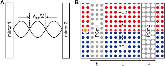
FIGURE 1. (A) Sketch of a traditional FP cavity. Light of wavelength
Designs and Results
Optical Topological Cavity Type I
As shown in Figure 1A, a traditional FP cavity is composed of parallel cavity mirrors and a lasing medium in between. The laser wavelength
Here, we consider the transverse magnetic (TM, with electric field
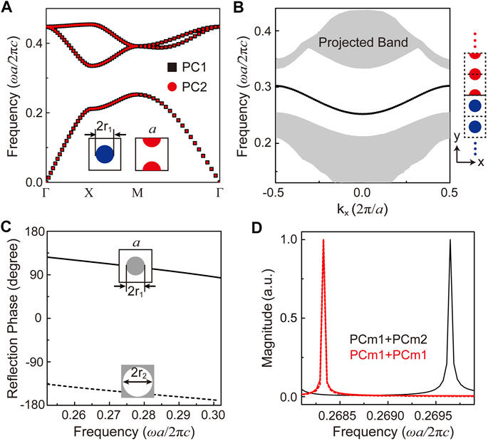
FIGURE 2. (A) TM photonic band diagrams of PC1 and PC2 with shifted lattice. (B) Calculated projected band structure with a supercell of PC1 and PC2 assembled along the y direction. The folded bulk bands of PC1 and PC2 are painted in gray, and the interface state is in black. (C) The reflection phases upon PC mirrors. (D) By changing PC mirrors, the cavity mode frequency will change. Red lines indicate the scenario where PCm1 serves as both cavity mirrors, and the black line indicates the scenario where PCm1 and PCm2 serve as the two cavity mirrors, respectively. A slab of effective parameters ε = −2.8 and μ = 1.2 with a reflection phase 113.578°is also considered to replace PCm1, whose reflection phase is the same as that of PCm1 at 0.2683 c/a.
In the studies of traditional FP cavities, the reflection phase of mirrors has never been considered. The major reason is that in a traditional FP cavity, metallic mirrors are considered with a 180° reflection phase. During the back-and-forth bouncing between these two mirrors, no phase accumulation will occur. On the contrary, although total reflection occurs on PCm1/PCm2, the frequency shift we observe shall correspond to their different reflection phases. Electromagnetic waves propagate along the interface and then bounce back on one PC mirror with the accumulated phase and propagate again along the interface. Thus, the FP condition of a cavity shall be revised as
where
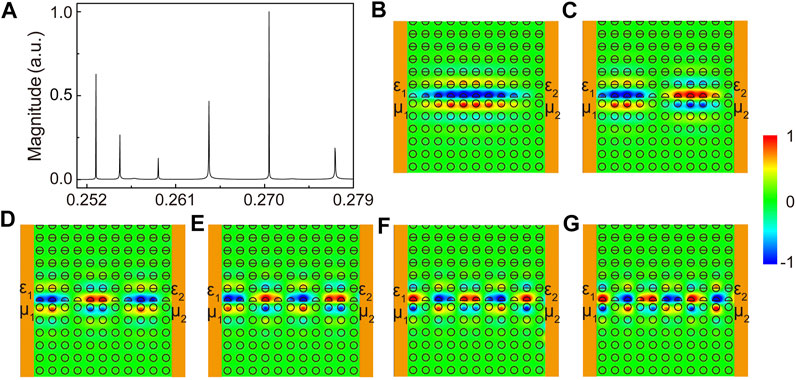
FIGURE 3. (A) The calculated transmission spectrum with PC mirrors replaced by single negative effective medium slabs. (B–G) Simulated
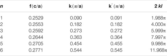
Further analysis is conducted as shown in Table 1. We can find its corresponding wave number k at the transmission spectrum peak frequency in our calculated dispersion, as shown in Figure 2B. Thus, the total phase accumulation 2 kl with
Optical Topological Cavity Type II
Using Zak phase–induced interfaces, we have successfully constructed OTC type I and discovered the role PC mirrors play in the mode selection. As various applications have been demonstrated utilizing the unidirectional interface states induced by the valley-spin Hall effect, we extend our work to construct OTC type II by using valley-spin Hall PCs. By introducing sublattice symmetry breaking into the honeycomb lattice PC [25], unidirectional interface states are induced and adopted to construct OTC type II. We consider PC3 and PC4 with inverted inversion symmetry. Here, three honeycomb lattices are considered as an enlarged hexagonal unit cell, with six dielectric cylinders with permittivity
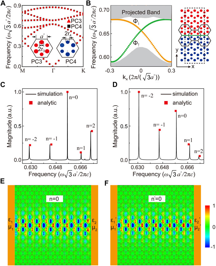
FIGURE 4. (A) Calculated bulk TM photonic band diagrams of PC3 and PC4. As the diameters of cylinders in a unit cell are not identical in both PC3 and PC4 (
We have shown in the previous section that using an effective medium slab can explain the role of PC mirrors in constructing an OTC, and thus, a pair of effective medium mirrors with zero total-reflecting phases is first considered here to construct OTC type II with
The unidirectional property of valley–spin Hall interface states provides a totally different picture of the electromagnetic wave propagation inside OTC type II. As our source is on the left side of the OTC, only the valley pseudospin up state (the green-colored dispersion in Figure 4B) is excited to propagate rightward, whose wave number is decided by the corresponding frequency. With its linear dispersion, both positive and negative values of the wave number are possible and correspond to different frequencies. When bounced on the right mirror, the pseudospin up state must be flipped to the pseudospin down state as for the unidirectional property and a change of dispersion occurs. However, although the sign of the wave number changes accordingly, as for leftward propagation, further phase accumulation will occur to satisfy the FP condition as shown in Eq. 1. The phenomenon will be identical if the source is put on the right side of the OTC with an identical transmission spectrum to be received on the left side of the OTC. However, if the leftward propagation valley pseudospin down state is considered first, which is the case with source on the right, mode index n will be reversed such that the sequence of the peaks shall read as 2, 1, 0, –1, and –2, as in Figures 4C and D, respectively. This is quite different from OTC type I with a Zak phase–induced interface state with only positive indices. With its quadratic dispersion, the frequency with wave number k is the same as that of –k and thus positive and negative indices are degenerate to each other.
The absence of n = 0 mode in OTC type I can also be understood from their dispersion difference. Although k = 0 (at Γ point) is possible for the Zak phase–induced interface state, time reversal symmetry requires that its dispersion be quadratic, whose group velocity is zero there. This slow light will not be physical and will not appear in our calculated spectrum. On the contrary, the finite group velocity of the linear dispersion of the valley–spin Hall effect at Γ point allows its emergence.
Knowing the physics of OTC type II, we can construct it using PC structures. We consider PC mirrors with deformed honeycomb lattice, where the positions of the six cylinders in PC3 and PC4 are changed. When the six cylinders in one unit cell are moved closer to the center of the unit cell, decreasing the intercylinder distance, a shrunken-latticed PCm3 is constructed where its expanded counterpart is considered as PCm4, both shown in gray in Figure 5A. The lattice deformation not only provides an extra mechanism for the bandgap opening of the linear dispersion of two interface states [35], but also leads to the quantum spin Hall effect of photonic crystals [36, 37]. With the bandgap of the interfacial state dispersion, PCm3 and PCm4 can serve as the PC mirrors for OTC type II. Of course, other honeycomb structures can be introduced as PC mirrors whose photonic bandgap frequency overlaps with the linear interfacial dispersion of the valley–spin Hall effect in the PC we design. The introduction of lattice deformation is the easiest approach (though not of the easiest geometry) to guarantee the bandgap with matched lattice. With the same dielectric material considered, this 2D design can be further extended to photonic slab geometry. The intercylinder distance is
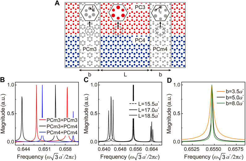
FIGURE 5. (A) Schematics of OTC type II and 2 PC cavity mirrors. PCm3 (PCm4) is considered with a shrunken (expanded) lattice compared to the PC structure considered at the interface region. (B) The mode selection of different PC mirror configurations. (C) The received transmission spectra with different cavity lengths. (D) By tuning the thickness of PC mirrors, the cavity fidelity will be enhanced (
Discussion and Conclusion
In summary, we extend the study of topology photonics to the construction of OTCs. Different topological invariants have been utilized for the generation of robust topological interface states with various applications triggered. Following the theoretical derivation based on the Zak phase and valley–spin Hall effect of light, respectively, different topologically induced interface states are designed and introduced in the construction of OTC type I (PCs with shifted lattice) and OTC type II (honeycomb lattice with broken inversion symmetry). Although one-to-one correspondence between a traditional FP optical planar mirror cavity and OTCs can be found, the quadratic interface dispersion in OTC type I and the linear interface dispersion in OTC type II govern the totally different mode selection criteria in the two OTCs. Negative and zeroth mode indices appear for OTC type II, solely because of its linear dispersion with topological origin. The zeroth mode maintains a constant working frequency irrespective of the length of the cavity.
We also extend the study of topological invariants to the design of the reflection phase in an OTC. We find that the reflection phase of PC mirrors adopted in the construction of OTC plays a key role in mode selection and will be essential when designing an OTC working at one particular frequency. The change of the topological invariant indicates a topology phase transition which also accompanies a dramatic reflection phase change at the associated photonic bandgap, which is verified for PC mirrors based on the Zak phase and quantum spin Hall effect. This new design principle to tune the reflection phase of PCs will help the future development of optical devices.
Data Availability Statement
The original contributions presented in the study are included in the article/Supplementary Material, and further inquiries can be directed to the corresponding author.
Author Contributions
ZH conceived the idea and wrote part of the manuscript. MY performed the numerical simulations and wrote part of the manuscript. MY and TX analyzed the results and prepared the figures. All authors have given approval to the final version of the manuscript.
Funding
This work is supported by the National Natural Science Foundation of China (Grant No. 11874274) and a project funded by the Priority Academic Program Development of Jiangsu Higher Education Institutions (PAPD). The authors are also grateful for the support from Jiangsu Key Laboratory of Thin Films and Jiangsu Key Lab of Advanced Optical Manufacturing Technologies.
Conflict of Interest
The authors declare that the research was conducted in the absence of any commercial or financial relationships that could be construed as a potential conflict of interest.
Acknowledgments
The authors would like to acknowledge Hua Jiang for his kind suggestions.
References
1. Haldane FDM, Raghu S. Possible Realization of Directional Optical Waveguides in Photonic Crystals with Broken Time-Reversal Symmetry. Phys Rev Lett (2008) 100:013904. doi:10.1103/PhysRevLett.100.013904
2. Raghu S, Haldane FDM. Analogs of Quantum-Hall-Effect Edge States in Photonic Crystals. Phys Rev A (2008) 78:033834. doi:10.1103/PhysRevA.78.033834
3. Khanikaev AB, Shvets G. Two-dimensional Topological Photonics. Nat Photon (2017) 11:763–73. doi:10.1038/s41566-017-0048-5
4. Ozawa T, Price HM, Amo A, Goldman N, Hafezi M, Lu L, et al. Topological Photonics. Rev Mod Phys (2019) 91:015006. doi:10.1103/RevModPhys.91.015006
5. Wang Z, Chong Y, Joannopoulos JD, Soljačić M. Observation of Unidirectional Backscattering-Immune Topological Electromagnetic States. Nature (2009) 461:772–5. doi:10.1038/nature08293
6. Sheng DN, Weng ZY, Sheng L, Haldane FDM. Quantum Spin-Hall Effect and Topologically Invariant Chern Numbers. Phys Rev Lett (2006) 97:036808. doi:10.1103/PhysRevLett.97.036808
7. Poo Y, Wu R, Lin Z, Yang Y, Chan CT. Experimental Realization of Self-Guiding Unidirectional Electromagnetic Edge States. Phys Rev Lett (2011) 106:093903. doi:10.1103/PhysRevLett.106.093903
8. Skirlo SA, Lu L, Soljačić M. Multimode One-Way Waveguides of Large Chern Numbers. Phys Rev Lett (2014) 113:113904. doi:10.1103/PhysRevLett.113.113904
9. Skirlo SA, Lu L, Igarashi Y, Yan Q, Joannopoulos J, Soljačić M. Experimental Observation of Large Chern Numbers in Photonic Crystals. Phys Rev Lett (2015) 115:253901. doi:10.1103/PhysRevLett.115.253901
10. Price HM, Zilberberg O, Ozawa T, Carusotto I, Goldman N. Measurement of Chern Numbers through Center-of-Mass Responses. Phys Rev B (2016) 93:245113. doi:10.1103/PhysRevB.93.245113
11. Zak J. Berry's Phase for Energy Bands in Solids. Phys Rev Lett (1989) 62:2747–50. doi:10.1103/PhysRevLett.62.2747
12. Xiao M, Ma G, Yang Z, Sheng P, Zhang ZQ, Chan CT. Geometric Phase and Band Inversion in Periodic Acoustic Systems. Nat Phys (2015) 11:240–4. doi:10.1038/NPHYS3228
13. Yang Y, Huang X, Hang ZH. Experimental Characterization of the Deterministic Interface States in Two-Dimensional Photonic Crystals. Phys Rev Appl (2016) 5:034009. doi:10.1103/PhysRevApplied.5.034009
14. Huang X, Yang Y, Hang ZH, Zhang ZQ, Chan CT. Geometric Phase Induced Interface States in Mutually Inverted Two-Dimensional Photonic Crystals. Phys Rev B (2016) 93:085415. doi:10.1103/PhysRevB.93.085415
15. Yang Y, Xu T, Xu YF, Hang ZH. Zak Phase Induced Multiband Waveguide by Two-Dimensional Photonic Crystals. Opt Lett (2017) 42:3085–8. doi:10.1364/OL.42.003085
16. Zhao W, Xu YF, Yang Y, Tao Z, Hang ZH. Multiband Acoustic Waveguides Constructed by Two-Dimensional Phononic Crystals. Appl Phys Express (2020) 13:094001. doi:10.35848/1882-0786/abafc7
17. Ma T, Shvets G. All-Si valley-hall Photonic Topological Insulator. New J Phys (2016) 18:025012. doi:10.1088/1367-2630/18/2/025012
18. Dong J-W, Chen X-D, Zhu H, Wang Y, Zhang X. Valley Photonic Crystals for Control of Spin and Topology. Nat Mater (2017) 16:298–302. doi:10.1038/NMAT4807
19. Yan M, Lu J, Li F, Deng W, Huang X, Ma J, et al. On-chip valley Topological Materials for Elastic Wave Manipulation. Nat Mater (2018) 17:993–8. doi:10.1038/s41563-018-0191-5
20. Ye L, Yang Y, Hong Hang Z, Qiu C, Liu Z. Observation of valley-selective Microwave Transport in Photonic Crystals. Appl Phys Lett (2017) 111:251107. doi:10.1063/1.5009597
21. Gao F, Xue H, Yang Z, Lai K, Yu Y, Lin X, et al. Topologically Protected Refraction of Robust Kink States in valley Photonic Crystals. Nat Phys (2018) 14:140–4. doi:10.1038/NPHYS4304
22. Shalaev MI, Walasik W, Tsukernik A, Xu Y, Litchinitser NM. Robust Topologically Protected Transport in Photonic Crystals at Telecommunication Wavelengths. Nat Nanotech (2019) 14:31–4. doi:10.1038/s41565-018-0297-6
23. He X-T, Liang E-T, Yuan J-J, Qiu H-Y, Chen X-D, Zhao F-L, et al. A Silicon-On-Insulator Slab for Topological valley Transport. Nat Commun (2019) 10:872. doi:10.1038/s41467-019-08881-z
24. Mittal S, Fan J, Faez S, Migdall A, Taylor JM, Hafezi M. Topologically Robust Transport of Photons in a Synthetic Gauge Field. Phys Rev Lett (2014) 113:087403. doi:10.1103/PhysRevLett.113.087403
25. Yang Y, Jiang H, Hang ZH. Topological Valley Transport in Two-Dimensional Honeycomb Photonic Crystals. Sci Rep (2018) 8:1588. doi:10.1038/s41598-018-20001-3
26. Smirnova D, Leykam D, Chong Y, Kivshar Y. Nonlinear Topological Photonics. Appl Phys Rev (2020) 7:021306. doi:10.1063/1.5142397
27. St-Jean P, Goblot V, Galopin E, Lemaître A, Ozawa T, Le Gratiet L, et al. Lasing in Topological Edge States of a One-Dimensional Lattice. Nat Photon (2017) 11:651–6. doi:10.1038/s41566-017-0006-2
28. Parto M, Wittek S, Hodaei H, Harari G, Bandres MA, Ren J, et al. Edge-mode Lasing in 1D Topological Active Arrays. Phys Rev Lett (2018) 120:113901. doi:10.1103/PhysRevLett.120.113901
29. Bahari B, Ndao A, Vallini F, El Amili A, Fainman Y, Kanté B. Nonreciprocal Lasing in Topological Cavities of Arbitrary Geometries. Science (2017) 358:636–40. doi:10.1126/science.aao4551
30. Zhao H, Miao P, Teimourpour MH, Malzard S, El-Ganainy R, Schomerus H, et al. Topological Hybrid Silicon Microlasers. Nat Commun (2018) 9:981. doi:10.1038/s41467-018-03434-2
31. Bandres MA, Wittek S, Harari G, Parto M, Ren J, Segev M, et al. Topological Insulator Laser: Experiments. Science (2018) 359:eaar4005. doi:10.1126/science.aar4005
32. Zeng Y, Chattopadhyay U, Zhu B, Qiang B, Li J, Jin Y, et al. Electrically Pumped Topological Laser with valley Edge Modes. Nature (2020) 578:246–50. doi:10.1038/s41586-020-1981-x
33. Shao Z-K, Chen H-Z, Wang S, Mao X-R, Yang Z-Q, Wang S-L, et al. A High-Performance Topological Bulk Laser Based on Band-Inversion-Induced Reflection. Nat Nanotechnol (2020) 15:67–72. doi:10.1038/s41565-019-0584-x
34.Comsol Multiphysics, v5.4 (https://cn.comsol.com)
35. Yang Y, Jia Z, Wu Y, Xiao R-C, Hang ZH, Jiang H, et al. Gapped Topological Kink States and Topological Corner States in Honeycomb Lattice. Sci Bull (2020) 65:531–7. doi:10.1016/j.scib.2020.01.024
36. Wu L-H, Hu X. Scheme for Achieving a Topological Photonic crystal by Using Dielectric Material. Phys Rev Lett (2015) 114:223901. doi:10.1103/PhysRevLett.114.223901
Keywords: photonic crystal, topological interface states, reflection phase, Zak phase, valley–spin Hall effect
Citation: Yuan M, Xu T and Hang ZH (2021) Construction of Optical Topological Cavities Using Photonic Crystals. Front. Phys. 9:697719. doi: 10.3389/fphy.2021.697719
Received: 20 April 2021; Accepted: 17 May 2021;
Published: 07 June 2021.
Edited by:
Guancong Ma, Hong Kong Baptist University, ChinaReviewed by:
Xueqin Huang, South China University of Technology, ChinaMeng Xiao, Hong Kong University of Science and Technology, China
Copyright © 2021 Yuan, Xu and Hang. This is an open-access article distributed under the terms of the Creative Commons Attribution License (CC BY). The use, distribution or reproduction in other forums is permitted, provided the original author(s) and the copyright owner(s) are credited and that the original publication in this journal is cited, in accordance with accepted academic practice. No use, distribution or reproduction is permitted which does not comply with these terms.
*Correspondence: Zhi Hong Hang, emhoYW5nQHN1ZGEuZWR1LmNu
 Meng Yuan
 Tao Xu
 Zhi Hong Hang1,3*