- 1School of Physics and Materials Science and Research Center for Advanced Information Materials, Guangzhou University, Guangzhou, China
- 2Institute for Advanced Materials and Guangdong Provincial Key Laboratory of Quantum Engineering and Quantum Materials, South China Normal University, Guangzhou, China
- 3Laboratory of Solid State Microstructures and Innovative Center of Advanced Microstructures, Nanjing University, Nanjing, China
Magnetic skyrmion in chiral magnet exhibits a variety of unique topological properties associated with its innate topological structure. This inspires a number of ongoing searching for new topological magnetic textures. In this work, we used micromagnetic simulations and Monte Carlo simulations to investigate an exotic Néel-type magnetic kinks in square-shaped nanostructures of chiral magnets, which performs rather stably in the absence of magnetic field. The individual magnetic kink can reside in one of the four possible corners, and carry possibly upward or downward core polarity, constituting eight degenerate states. In addition, these kinks also exhibit unique behaviors of generation, stability and dynamics, as revealed by micromagnetic simulations. It was found that such kinks can be created, annihilated, displaced, and polarity-reversed on demand by applying a spin-polarized current pulse, and are easily switchable among the eight degenerate states. In particularly, the kinks can be switched toward the ferromagnetic-like states and backward reversibly by applying two successive current pulses, indicating the capability of writing and deleting the kink structures. These findings predict the existence of Néel-type magnetic kinks in the square-shaped nanostructures, as well as provide us a promising approach to tailor the kinks by utilizing the corners of the nanostructures, and control these states by spin-polarized currents. The present work also suggests a theoretical guide to explore other chiral magnetic textures in nanostructures of polygon geometries.
1 Introduction
A magnetic skyrmion is a topologically stable configuration often observed in chiral magnets with broken inversion symmetry. The nanoscale skyrmion shows particle-like behavior, as it can be moved, created, and annihilated. These characters make it promising candidate as information carrier for future memory devices and logic devices [1–6]. It has thus aroused intense research efforts in recent years, leading to a series of breakthrough achievements in manipulation of skyrmion states, via injected spin-polarized currents, external electric-field, and so on [7–14]. For the application of skyrmions in spintronic devices, many feasible designs have been proposed for confining the skyrmions in geometric nanostructures, such as nanostripes and nanodisks, which may allow the precise control of individual skyrmions [8–10]. These achievements pave the way towards all-electrical manipulation schemes [2, 3], and underpin the skyrmion-based information storage concepts, such as the skyrmion-based racetrack memory, high density magnetic random access memory, and logic gates, etc. [2–6, 8, 9].
These fascinating physical properties also inspired an ongoing search for new types of magnetic topological textures, for instance, fractional skyrmion emerging in various chiral and frustrated magnets [15–21], which exhibit some unusual physical phenomena distinctly different from skyrmion-host chiral magnetic materials such as MnSi and Fe1-xCoxSi systems [22, 23]. Moreover, some recent observations indicated that fractional skyrmions also emerge in geometric nanostructures due to the effects of geometric confinement and shape anisotropy [24–28]. For example, it was observed in Lorentz transmission electron microscopy (TEM) images of FeGe nanostripes that, the skyrmions survive when the width of the nanostripe much larger than the single skyrmion size, whereas some merons form at the edges that are not large enough for accommodating a complete skyrmion [24, 25].
Generally, the presence of edges and corners in nanostructures can be utilized to tailor the magnetic textures and modify their dynamics behaviors. For the skyrmion confined in ultrathin film nanostructures with Dzyaloshinskii-Moriya (DM) interaction, the boundary constrictions naturally make the magnetization orientation undergo the 180° rotation at the edges, forming the so-called kink or π domain wall configurations [2, 15, 29–32]. Depending on the crystal symmetry of chiral magnets, two distinct types of chiral kinks, namely, Néel-type and Bloch-type kinks, are favorable in interfacial and bulk DM interaction systems respectively [29, 30]. It had been theoretically proposed in chiral magnets that the skyrmions, antiskyrmions, and other magnetic configurations can be naturally interpreted in terms of chiral kinks. These kinks carry a topological charge and allow to construct new topological particle-like states [15, 31, 32]. In addition, the previous studies demonstrated that some special magnetic textures often appear in the corners of the polygon geometries like triangles, squares, rectangles, in which the corners may also act as pinning sites for the domain wall motion [33–36]. This indicates that the nanostructure with polygon geometries may provide a unique platform for studying the kink structures, favoring the control of the magnetic states, by utilizing their edges and corners. Certainly, there are more open questions to be explored along this line. For instance, is it possible to realize some new kink structures beyond the skyrmions and merons in nanostructures? Is it possible the kink structures stable in nanostructures without the assistance of external magnetic field? Is it possible to manipulate these kinks by pure electric currents? These issues are very critical for our understanding the physical properties of the new type chiral magnetic structures in confined nanostructures.
Inspired by this motivation, the purpose of our work is to explore new kink structures in nanostructures by using micromagnetic simulations and Monte Carlo simulations. In this work, we aimed at studying the square-shaped nanostructures with width smaller than the single skyrmion size. We demonstrated an exotic Néel-type kink structure, which can stably exist in the corners of the square-shaped nanostructures in the absence of external magnetic field. Such kinks possess eight switchable degenerate states and can be created, annihilated, displaced, and polarity-reversed by applying spin-polarized currents.
2 Model and Simulation Methods
In this work, the magnetic state in an ultrathin square nanostructure of chiral magnets is described by a classical Heisenberg model. The Hamiltonian consists of ferromagnetic exchange interaction
where the magnetic moments are imposed on a two-dimensional
To investigate the dynamics of the magnetic structures driven by the spin-polarized current, we numerically solved the Landau-Lifshitz-Gilbert (LLG) equation by using fourth-order Runge-Kutta method [8, 10, 41, 42]:
with the effective field
The skyrmion motion can be driven by spin-polarized current flowing in the nanostructure along either the in-plane or out-of-plane direction. For simulations of the skyrmion dynamics induced by the current-in-plane (CIP) injection, the corresponding torque
where the first and second terms represent the coupling between magnetic moments and spin-polarized current
For the current-perpendicular-to-plane (CPP) injection, the current-induced spin transfer torque
where
To get the zero-temperature equilibrium state, we adopted a specific simulation scheme: the lattice was initialized as a paramagnetic phase at sufficiently high temperature, and annealed for obtaining the state at a low temperature, by using the Metropolis Monte Carlo simulation combined with over-relaxation algorithm [17, 18, 44]. Then the configuration was further relaxed for the equilibrium state, by solving the LLG equation under
In addition, the kink dynamics is controlled by injecting a CIP-type or CPP-type spin-polarized current pulse on demand. We introduced the schemes in our simulations for setting the amplitude and duration of current pulses as follows: 1) First, we tested the effect of amplitude of current density on the kink dynamics and chose the suitable amplitude of current pulses for control (generation, creation, annihilation, displacement or polarity reversal) of the kink states. 2) Then we carefully tracked its dynamics and turned off the current once the germinal kink appears or kink shifts (in this procedure, the current duration is determined), and further relaxed the system by solving LLG equation under zero-current condition to get an equilibrium kink state.
3 Simulation Results
3.1 Size Effect of Nanostructures on the Magnetic Structures
We first investigated the size effect of the nanostructures on magnetic structures. The simulations were carried out on a
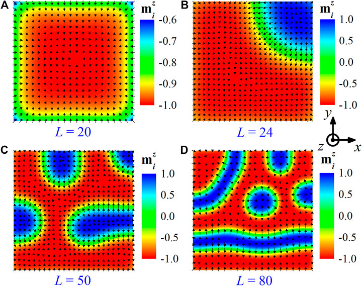
FIGURE 1. Size effect of nanostructures on the equilibrium magnetic states. Some typical magnetic configurations are shown for square-shaped nanostructures with lateral sizes of (A)
As one may see in Figure 1A, a bubble domain arises in the square nanostructure at small lateral size
3.2 Néel-Type Magnetic Kinks
Now we focus on the intriguing features of kink-like structures and analyzing their current-induced dynamics in this paper. For this, we adopted a small square shaped nanomagnet consisting of 24 × 24 square lattices (∼12 × 12 nm) for studying the kink-like structure, in the rest part of this work. We first tested the stability of the kink-like structure in Figure 1B once the magnetic field was removed. For this, the magnetic structure was relaxed for the equilibrium state by solving the LLG equation, in which we used the kink-like state shown in Figure 1B as the initial state, and set
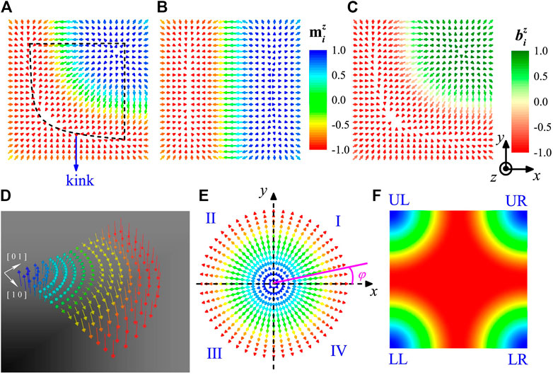
FIGURE 2. (A) The magnetic structure obtained from the above state in Figure 1B after withdrawal of magnetic field. A kink structure is enclosed by the dash lines. (B) A spiral structure, as the possible ground state of nanostructure with a size of 24 × 24 square lattices (i.e., ∼12 × 12 nm) in the absence of magnetic field.(C) The reduced effective field
To explore the possible ground state for the nanomagnet of 24 × 24 square lattices at
To further estimate the stability of the metastable Néel-type kink state under
In fact, one may take account of the kink structures from the prototypical Néel skyrmion, whose configuration can be viewed as a coplanar spiral with magnetic moments lying in a plane perpendicular to the xy plane [1, 38]:
where the spatial variables of magnetization are defined in polar coordinates
To proceed, one may divide an isolated skyrmion configuration into four quadrants along the dash lines, as illustrated in Figure 2E. The magnetic structures in quadrant I, II, III, and IV can be described by Eq. 5, with the azimuthal angle 0
3.3 Generation and Switching of Kinks by In-Plane Current Pulse
In this section, we studied the generation of kinks by injecting into the nanostructure an in-plane spin-polarized current pulse. Here, the direction of the CIP injection is defined by the angle φ with respect to the x-axis (see in Figure 3B), and
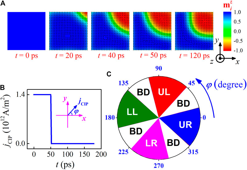
FIGURE 3. The generation of kink from the initial ferromagnetic state, by injecting into the nanostructure an in-plane spin-polarized current pulse. (A) Snapshots show the formation process of the UR kink, driven by the current pulse with injection angle
The simulations start from the initial ferromagnetic phase, with all magnetic moments aligning along z-axis at
Further simulations demonstrated that the generation of kinks is sensitive to injection angle φ, with the simulated results summarized in Figure 3C. It was found that the UR, UL, LL, and LR quarters can also be created respectively for −42° ≤
Next, we investigated the switching between these kinks using in-plane current pulse, which is fundamental to understand their dynamics properties. The current pulse (
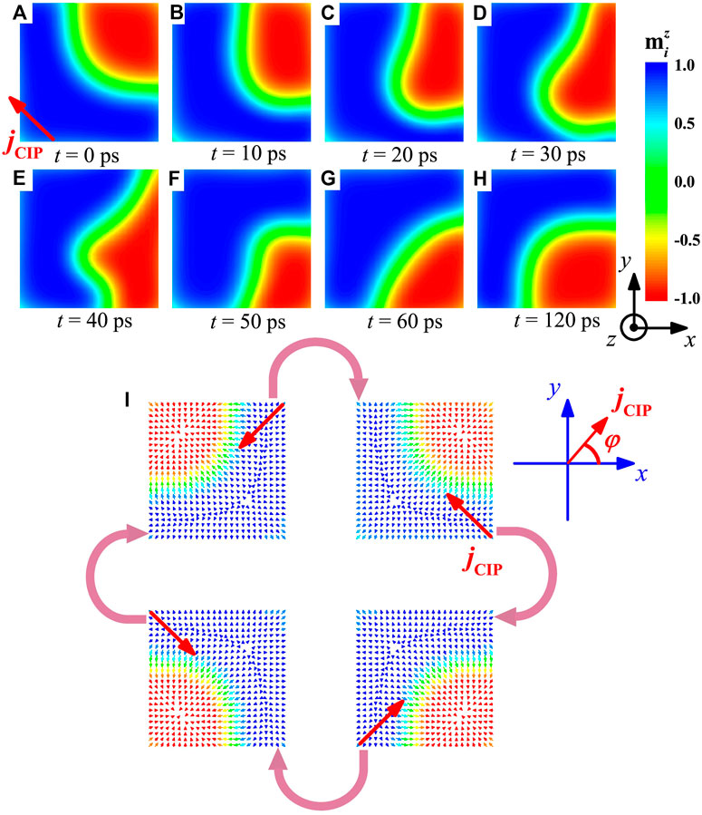
FIGURE 4. (A)–(H) The gradual shift of kink from UR to LR corner, driven by in-plane current pulse with current density
3.4 Annihilation and Creation of Kinks by In-Plane Current Pulses
In this section, we presented an effective way to annihilate and create the kink by applying two successive CIP pulses, as the results shown in Figure 5. Our simulations start from the initial UR kink state with
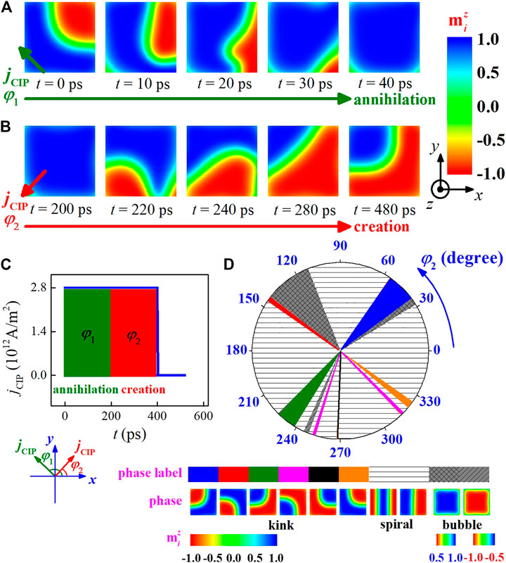
FIGURE 5. The annihilation and creation of kink is achieved by applying CIP current pulses. (A) and (B) Snapshots show a typical case for the annihilation and creation process of kink induced by two successional current pulses with injection angle
More interestingly, the simulated results reveal that some other kink states can be created from the ferromagnetic-like state, by applying the second current pulse with varying injection angle
Further simulations generate the phase diagram for the equilibrated states at
3.5 Manipulation of Kinks by Out-of-Plane Current Pulse
In this section, we investigated the core polarity reversal of the kinks with out-of-plane current, which is also a fundamental issue for understanding their dynamics properties. One may build a magnetic tunnel junction (MTJ) or spin valve to locally address the kinks [5, 53]. As schematically shown in Figure 6A, a typical MTJ structure consists of the top and bottom two layers of ferromagnet, which is separated by an ultrathin spacer of insulator. The top ferromagnetic layer is a free layer which presents a kink state, while the bottom one is a fixed layer with the magnetization
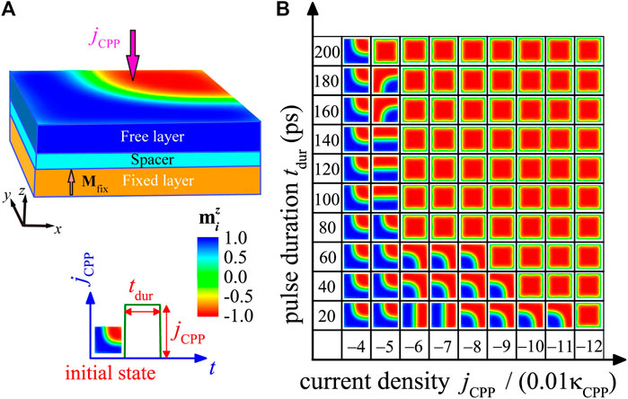
FIGURE 6. (A) Sketch of a MTJ nanopillar consisting of the top and bottom layers of ferromagnet, and the spacer layer of insulator. (B) Simulations for the evolutions of kink driven by a CPP pulse, starting from an initial kink with
We first studied the dynamics of the kink driven by various current densities
To further investigate the repeatability of polarity reversals of kink driven by CPP pulses, we took an examination on injecting some discontinuous current pulses to the system, as presented in Figure 7A. The insert shows the kink states at some typical time before and after the pulse injections in the evolutions. It was observed that all the four CPP pulses reverse the kink polarity, and the pulse with spin current
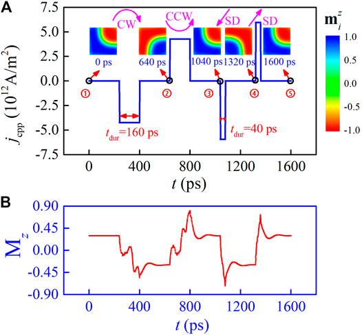
FIGURE 7. (A) The polarity reversal of kinks induced by CPP pulses, accompanying with the displacements of kinks. The first and second CPP pulses with
4 Discussion and Conclusion
Before concluding this work, we briefly discuss the experimental observations and thermal stability of the kink states. The X-ray holography allow the imaging of ultrafast magnetization dynamics in magnetic nanostructure with sub-10 nm spatial resolution time-resolved [6]. Using time-resolved X-ray microscopy, a number of experimental studies reported the direct observation of nanoscale skyrmions, current-driven skyrmions dynamics, and the detailed evolution of magnetic configuration during the writing and deleting a skyrmion process [54, 55].
On the other hand, all simulations in present study were calculated under zero temperature in which the thermal effect is neglected. However, the thermal stability of magnetic kink structure is also a crucial issue for a detailed understanding of their underlying physical properties. For this, we tested the effect of thermal fluctuation on the magnetic structure by using Monte Carlo simulation with ladder cooling protocol [44]. It was found that the magnetic structure may forms at a very low-temperature T ≤ 1.2
In summary, we used micromagnetic simulations and Monte Carlo simulations to investigate an exotic Néel-type kink texture in square-shaped nanostructures, which may stably exist in the absence of magnetic field. It was interesting to find that individual kinks hold eight degenerate states as they can reside in one of the four possible corners of a nanostructure, and carry upward or downward polarity. In addition, we proposed some effective schemes to control their dynamics by means of injecting spin-polarization current pulses. It was found that kinks can be created, annihilated, displaced and reversed polarity on demand by applying an in-plane or an out-of-plane spin-polarized current pulse, and are facile switchable among the degenerate kink states. In particularly, the kinks can be switched toward the ferromagnetic-like states and backward reversibly by applying two successive current pulses, indicating the capability of writing and deleting the kink states. These findings predict the existence of Néel-type kinks in the square-shaped nanostructures, as well as provide us a promising approach to tailor the kinks by utilizing the corners of the nanostructures, and control these states by spin-polarized currents. This study also suggests a theoretical guide to explore other chiral magnetic textures in nanostructures of polygon geometries.
Data Availability Statement
The original contributions presented in the study are included in the article/Supplementary Material, further inquiries can be directed to the corresponding author.
Author Contributions
J-PC and X-SG conceived the research project, and J-PC performed the computations. J-PC, J-QL, XS, YC, Z-FC, W-AL, M-HQ, Z-PH, X-SG, and J-ML commented the modeling and discussed the results. J-PC and X-SG wrote the manuscript.
Funding
This work was supported by the Natural Science Foundation of China (11604059), the Natural Science Foundation of Guangdong Province, China (2017A030313020), Scientific Research Project of Guangzhou Municipal Colleges and Universities (1201630455) and the Guangzhou University’s Training Program for Excellent New-recruited Doctors (YB201715).
Conflict of Interest
The authors declare that the research was conducted in the absence of any commercial or financial relationships that could be construed as a potential conflict of interest.
Publisher’s Note
All claims expressed in this article are solely those of the authors and do not necessarily represent those of their affiliated organizations, or those of the publisher, the editors and the reviewers. Any product that may be evaluated in this article, or claim that may be made by its manufacturer, is not guaranteed or endorsed by the publisher.
References
1. Nagaosa N, Tokura Y. Topological Properties and Dynamics of Magnetic Skyrmions. Nat Nanotech (2013) 8:899–911. doi:10.1038/nnano.2013.243
2. Fert A, Reyren N, Cros V. Magnetic Skyrmions: Advances in Physics and Potential Applications. Nat Rev Mater (2017) 2:17031. doi:10.1038/natrevmats.2017.31
3. Wiesendanger R. Nanoscale Magnetic Skyrmions in Metallic Films and Multilayers: a New Twist for Spintronics. Nat Rev Mater (2016) 1:16044. doi:10.1038/natrevmats.2016.44
4. Jiang W, Chen G, Liu K, Zang J, te Velthuis SGE, Hoffmann A. Skyrmions in Magnetic Multilayers. Phys Rep (2017) 704:1–49. doi:10.1016/j.physrep.2017.08.001
5. Kang W, Huang Y, Zhang X, Zhou Y, Zhao W. Skyrmion-electronics: an Overview and Outlook. Proc IEEE (2016) 104:2040–61. doi:10.1109/JPROC.2016.2591578
6. Zhang X, Zhou Y, Mee Song K, Park T-E, Xia J, Ezawa M, et al. Skyrmion-electronics: Writing, Deleting, reading and Processing Magnetic Skyrmions toward Spintronic Applications. J Phys Condens Matter (2020) 32:143001. doi:10.1088/1361-648X/ab5488
7. Romming N, Hanneken C, Menzel M, Bickel JE, Wolter B, von Bergmann K, et al. Writing and Deleting Single Magnetic Skyrmions. Science (2013) 341:636–9. doi:10.1126/science.1240573
8. Sampaio J, Cros V, Rohart S, Thiaville A, Fert A. Nucleation, Stability and Current-Induced Motion of Isolated Magnetic Skyrmions in Nanostructures. Nat Nanotech (2013) 8:839–44. doi:10.1038/nnano.2013.210
9. Fert A, Cros V, Sampaio J. Skyrmions on the Track. Nat Nanotech (2013) 8:152–6. doi:10.1038/nnano.2013.29
10. Iwasaki J, Mochizuki M, Nagaosa N. Current-induced Skyrmion Dynamics in Constricted Geometries. Nat Nanotech (2013) 8:742–7. doi:10.1038/nnano.2013.176
11. Hsu P-J, Kubetzka A, Finco A, Romming N, von Bergmann K, Wiesendanger R. Electric-field-driven Switching of Individual Magnetic Skyrmions. Nat Nanotech (2017) 12:123–6. doi:10.1038/nnano.2016.234
12. Jiang W, Upadhyaya P, Zhang W, Yu G, Jungfleisch MB, Fradin FY, et al. Blowing Magnetic Skyrmion Bubbles. Science (2015) 349:283–6. doi:10.1126/science.aaa1442
13. Wang Y, Wang L, Xia J, Lai Z, Tian G, Zhang X, et al. Electric-field-driven Non-volatile Multi-State Switching of Individual Skyrmions in a Multiferroic Heterostructure. Nat Commun (2020) 11:3577. doi:10.1038/s41467-020-17354-7
14. Yao X, Chen J, Dong S. Controlling the Helicity of Magnetic Skyrmions by Electrical Field in Frustrated Magnets. New J Phys (2020) 22:083032. doi:10.1088/1367-2630/aba1b3
15. Göbel B, Mertig I, Tretiakov OA. Beyond Skyrmions: Review and Perspectives of Alternative Magnetic Quasiparticles. Phys Rep (2021) 895:1–28. doi:10.1016/j.physrep.2020.10.001
16. Lin S-Z, Saxena A, Batista CD. Skyrmion Fractionalization and Merons in Chiral Magnets with Easy-Plane Anisotropy. Phys Rev B (2015) 91:224407. doi:10.1103/PhysRevB.91.224407
17. Chen JP, Zhang D-W, Liu J-M. Exotic Skyrmion Crystals in Chiral Magnets with Compass Anisotropy. Sci Rep (2016) 6:29126. doi:10.1038/srep29126
18. Chen JP, Zhang D-W, Chen Y, Gao XS, Liu J-M. Compass-anisotropy-modulated Helical States and Skyrmion Crystals in Chiral Magnets. Phys Lett A (2018) 382:2944–51. doi:10.1016/j.physleta.2018.06.035
19. Kanazawa N, Kim J-H, Inosov DS, White JS, Egetenmeyer N, Gavilano JL, et al. Possible Skyrmion-Lattice Ground State in theB20chiral-Lattice Magnet MnGe as Seen via Small-Angle Neutron Scattering. Phys Rev B (2012) 86:134425. doi:10.1103/PhysRevB.86.134425
20. Yu XZ, Koshibae W, Tokunaga Y, Shibata K, Taguchi Y, Nagaosa N, et al. Transformation between Meron and Skyrmion Topological Spin Textures in a Chiral Magnet. Nature (2018) 564:95–8. doi:10.1038/s41586-018-0745-3
21. Gao S, Rosales HD, Gómez Albarracín FA, Tsurkan V, Kaur G, Fennell T, et al. Fractional Antiferromagnetic Skyrmion Lattice Induced by Anisotropic Couplings. Nature (2020) 586:37–41. doi:10.1038/s41586-020-2716-8
22. Yu XZ, Onose Y, Kanazawa N, Park JH, Han JH, Matsui Y, et al. Real-space Observation of a Two-Dimensional Skyrmion crystal. Nature (2010) 465:901–4. doi:10.1038/nature09124
23. Mühlbauer S, Binz B, Jonietz F, Pfleiderer C, Rosch A, Neubauer A, et al. Skyrmion Lattice in a Chiral Magnet. Science (2009) 323:915–9. doi:10.1126/science.1166767
24. Du H, Che R, Kong L, Zhao X, Jin C, Wang C, et al. Edge-mediated Skyrmion Chain and its Collective Dynamics in a Confined Geometry. Nat Commun (2015) 6:8504. doi:10.1038/ncomms9504
25. Jin C, Li Z-A, Kovács A, Caron J, Zheng F, Rybakov FN, et al. Control of Morphology and Formation of Highly Geometrically Confined Magnetic Skyrmions. Nat Commun (2017) 8:15569. doi:10.1038/ncomms15569
26. Xing X, Pong PWT, Zhou Y. Current-controlled Unidirectional Edge-Meron Motion. J Appl Phys (2016) 120:203903. doi:10.1063/1.4968574
27. Leonov AO, Mostovoy M. Edge States and Skyrmion Dynamics in Nanostripes of Frustrated Magnets. Nat Commun (2017) 8:14394. doi:10.1038/ncomms14394
28. Zhou Y, Ezawa M. A Reversible Conversion between a Skyrmion and a Domain-wall Pair in a junction Geometry. Nat Commun (2014) 5:4652. doi:10.1038/ncomms5652
29. Rohart S, Thiaville A. Skyrmion Confinement in Ultrathin Film Nanostructures in the Presence of Dzyaloshinskii-Moriya Interaction. Phys Rev B (2013) 88:184422. doi:10.1103/PhysRevB.88.184422
30. Heinonen O, Jiang W, Somaily H, te Velthuis SGE, Hoffmann A. Generation of Magnetic Skyrmion Bubbles by Inhomogeneous Spin Hall Currents. Phys Rev B (2016) 93:094407. doi:10.1103/PhysRevB.93.094407
31. Kuchkin VM, Barton-Singer B, Rybakov FN, Blügel S, Schroers BJ, Kiselev NS. Magnetic Skyrmions, Chiral Kinks, and Holomorphic Functions. Phys Rev B (2020) 102:144422. doi:10.1103/PhysRevB.102.144422
32. Cheng R, Li M, Sapkota A, Rai A, Pokhrel A, Mewes T, et al. Magnetic Domain wall Skyrmions. Phys Rev B (2019) 99:184412. doi:10.1103/PhysRevB.99.184412
33. Zheng Y, Chen WJ. Characteristics and Controllability of Vortices in Ferromagnetics, Ferroelectrics, and Multiferroics. Rep Prog Phys (2017) 80:086501. doi:10.1088/1361-6633/aa5e03
34. Cowburn RP, Welland ME. Micromagnetics of the Single-Domain State of Square Ferromagnetic Nanostructures. Phys Rev B (1998) 58:9217–26. doi:10.1103/PhysRevB.58.9217
35. Jaafar M, Yanes R, Perez de Lara D, Chubykalo-Fesenko O, Asenjo A, Gonzalez EM, et al. Control of the Chirality and Polarity of Magnetic Vortices in Triangular Nanodots. Phys Rev B (2010) 81:054439. doi:10.1103/PhysRevB.81.054439
36. Yao J, Song X, Gao X, Tian G, Li P, Fan H, et al. Electrically Driven Reversible Magnetic Rotation in Nanoscale Multiferroic Heterostructures. ACS Nano (2018) 12:6767–76. doi:10.1021/acsnano.8b01936
37. Keesman R, Leonov AO, van Dieten P, Buhrandt S, Barkema GT, Fritz L, et al. Degeneracies and Fluctuations of Néel Skyrmions in Confined Geometries. Phys Rev B (2015) 92:134405. doi:10.1103/PhysRevB.92.134405
38. Banerjee S, Rowland J, Erten O, Randeria M. Enhanced Stability of Skyrmions in Two-Dimensional Chiral Magnets with Rashba Spin-Orbit Coupling. Phys Rev X (2014) 4:031045. doi:10.1103/PhysRevX.4.031045
39. Romming N, Kubetzka A, Hanneken C, von Bergmann K, Wiesendanger R. Field-dependent Size and Shape of Single Magnetic Skyrmions. Phys Rev Lett (2015) 114:177203. doi:10.1103/PhysRevLett.114.177203
40. von Malottki S, Dupé B, Bessarab PF, Delin A, Heinze S. Enhanced Skyrmion Stability Due to Exchange Frustration. Sci Rep (2017) 7:12299. doi:10.1038/s41598-017-12525-x
41. Iwasaki J, Mochizuki M, Nagaosa N. Universal Current-Velocity Relation of Skyrmion Motion in Chiral Magnets. Nat Commun (2013) 4:1463. doi:10.1038/ncomms2442
42. Zhang X, Zhou Y, Ezawa M. Magnetic Bilayer-Skyrmions without Skyrmion Hall Effect. Nat Commun (2016) 7:10293. doi:10.1038/ncomms10293
43. Zhang S, Levy PM, Fert A. Mechanisms of Spin-Polarized Current-Driven Magnetization Switching. Phys Rev Lett (2002) 88:236601. doi:10.1103/PhysRevLett.88.236601
44. Chen JP, Wang ZQ, Gong JJ, Qin MH, Zeng M, Gao XS, et al. Stripe-vortex Transitions in Ultrathin Magnetic Nanostructures. J Appl Phys (2013) 113:054312. doi:10.1063/1.4790483
45. Hagemeister J, Iaia D, Vedmedenko EY, von Bergmann K, Kubetzka A, Wiesendanger R. Skyrmions at the Edge: Confinement Effects in Fe/Ir(111). Phys Rev Lett (2016) 117:207202. doi:10.1103/PhysRevLett.117.207202
46. Wilson MN, Butenko AB, Bogdanov AN, Monchesky TL. Chiral Skyrmions in Cubic Helimagnet Films: The Role of Uniaxial Anisotropy. Phys Rev B (2014) 89:094411. doi:10.1103/PhysRevB.89.094411
47. Chen JP, Xie YL, Chu P, Wang ZQ, Wang YL, Gao XS, et al. Manipulation of Magnetic State in Nanostructures by Perpendicular Anisotropy and Magnetic Field. J Appl Phys (2014) 115:243910. doi:10.1063/1.4885158
48. Büttner F, Moutafis C, Schneider M, Krüger B, Günther CM, Geilhufe J, et al. Dynamics and Inertia of Skyrmionic Spin Structures. Nat Phys (2015) 11:225–8. doi:10.1038/nphys3234
49. Liu Y, Du H, Jia M, Du A. Switching of a Target Skyrmion by a Spin-Polarized Current. Phys Rev B (2015) 91:094425. doi:10.1103/PhysRevB.91.094425
50. Kim J-V, Garcia-Sanchez F, Sampaio J, Moreau-Luchaire C, Cros V, Fert A. Breathing Modes of Confined Skyrmions in Ultrathin Magnetic Dots. Phys Rev B (2014) 90:064410. doi:10.1103/PhysRevB.90.064410
51. Liu Y, Gliga S, Hertel R, Schneider CM. Current-induced Magnetic Vortex Core Switching in a Permalloy Nanodisk. Appl Phys Lett (2007) 91:112501. doi:10.1063/1.2780107
52. Yamada K, Kasai S, Nakatani Y, Kobayashi K, Kohno H, Thiaville A, et al. Electrical Switching of the Vortex Core in a Magnetic Disk. Nat Mater (2007) 6:270–3. doi:10.1038/nmat1867
53. Finocchio G, Büttner F, Tomasello R, Carpentieri M, Kläui M. Magnetic Skyrmions: from Fundamental to Applications. J Phys D: Appl Phys (2016) 49:423001. doi:10.1088/0022-3727/49/42/423001
54. Büttner F, Lemesh I, Schneider M, Pfau B, Günther CM, Hessing P, et al. Field-free Deterministic Ultrafast Creation of Magnetic Skyrmions by Spin-Orbit Torques. Nat Nanotech (2017) 12:1040–4. doi:10.1038/nnano.2017.178
55. Woo S, Song KM, Han H-S, Jung M-S, Im M-Y, Lee K-S, et al. Spin-orbit Torque-Driven Skyrmion Dynamics Revealed by Time-Resolved X-ray Microscopy. Nat Commun (2017) 8:15573. doi:10.1038/ncomms15573
56. Lindner P, Bargsten L, Kovarik S, Friedlein J, Harm J, Krause S, et al. Temperature and Magnetic Field Dependent Behavior of Atomic-Scale Skyrmions in Pd/Fe/Ir(111) Nanoislands. Phys Rev B (2020) 101:214445. doi:10.1103/PhysRevB.101.214445
57. Büttner F, Lemesh I, Beach GSD. Theory of Isolated Magnetic Skyrmions: From Fundamentals to Room Temperature Applications. Sci Rep (2018) 8:4464. doi:10.1038/s41598-018-22242-8
58. Boulle O, Vogel J, Yang H, Pizzini S, de Souza Chaves D, Locatelli A, et al. Room-temperature Chiral Magnetic Skyrmions in Ultrathin Magnetic Nanostructures. Nat Nanotech (2016) 11:449–54. doi:10.1038/nnano.2015.315
59. Desplat L, Suess D, Kim J-V, Stamps RL. Thermal Stability of Metastable Magnetic Skyrmions: Entropic Narrowing and Significance of Internal Eigenmodes. Phys Rev B (2018) 98:134407. doi:10.1103/PhysRevB.98.134407
Keywords: magnetic kinks, chiral magnets, magnetic dynamics in nanostructures, micromagnetic simulations, spin-polarized currents
Citation: Chen J-P, Lin J-Q, Song X, Chen Y, Chen Z-F, Li W-A, Qin M-H, Hou Z-P, Gao X-S and Liu J-M (2021) Control of Néel-type Magnetic Kinks Confined in a Square Nanostructure by Spin-Polarized Currents. Front. Phys. 9:680698. doi: 10.3389/fphy.2021.680698
Received: 15 March 2021; Accepted: 07 July 2021;
Published: 28 July 2021.
Edited by:
Huaiyang Yuan, Utrecht University, NetherlandsReviewed by:
Juliano Denardin, University of Santiago, ChileKiyou Shibata, The University of Tokyo, Japan
Copyright © 2021 Chen, Lin, Song, Chen, Chen, Li, Qin, Hou, Gao and Liu. This is an open-access article distributed under the terms of the Creative Commons Attribution License (CC BY). The use, distribution or reproduction in other forums is permitted, provided the original author(s) and the copyright owner(s) are credited and that the original publication in this journal is cited, in accordance with accepted academic practice. No use, distribution or reproduction is permitted which does not comply with these terms.
*Correspondence: Ji-Pei Chen, Y2hlbmpwQGd6aHUuZWR1LmNu, Y2hhbmthaXB1aUAxNjMuY29t; Xing-Sen Gao, eGluZ3Nlbmdhb0BzY251LmVkdS5jbg==
 Ji-Pei Chen
 Jia-Qiang Lin1
 Zhi-Peng Hou
 Jun-Ming Liu