- 1Marine Engineering Institute, Jimei University, Xiamen, China
- 2Laboratory of Optics, Terahertz and Non-Destructive Testing, School of Mechanical Engineering and Automation, Fuzhou University, Fuzhou, China
An organic protective coating system plays an important role for the corrosion protection of offshore metallic structures. It is of practical importance to detect possible coating defects and evaluate coating performance for corrosion degradation monitoring. Reliable defect identification can provide timely and effective maintenance to avoid serious consequences. This work investigated various multilayer organic coating systems by terahertz pulse imaging technology and aimed to explore the inspection ability of terahertz non-destructive testing (THz NDT) of protective coatings. Several types of defective coating samples were measured. The comparison of measurements obtained for sites with and without defects was provided. The changes in the signals caused by the presence of defects were explained. Structural analysis, quantitative evaluation, and defect identification were carried out in detail. The results of measurements showed that corrosion defects, paint bulge defects, and paint detachment defects can be distinguished and identified in combination with the causes of defects. It can provide effective technical guidance for terahertz technology to be gradually extended to engineering applications.
Introduction
Organic protective coating is usually applied on the surfaces of marine or offshore structures for corrosion protection. Health monitoring of protective coatings especially non-destructive inspection of localized hidden defects can provide timely and effective maintenance for paint corrosion degradation [1, 2]. Several traditional methods are used to characterize the paint layers, such as electrochemical techniques and some commercially available thickness meters (ultrasonic testing, eddy-current testing, and infrared thermal wave detection, etc.,). However, each of them has its own detection bottleneck, which leads to limitation in application [3]. Terahertz time-domain spectroscopy (TD-THz) technology provides the capability for hands off inspection of organic coatings, and holds large potential in the field of industry application [4].
The applicability of terahertz non-destructive testing for organic protective coatings was verified earlier by Cook D et al., but they did not extend this to defective coating structure [5]. Recently, great progress has been made in coating structure analysis, such as coating thickness measurement [6]. Cheng B et al. proposed an optimization method to improve the detection resolution of top paint layer [7]. Non-contact measurement of multi-layered coating thickness was also investigated by Lin Y and coworkers [8]. Besides, coating integrity detection has also attracted significant attention. Anastasi R detected mechanical damage under the paint coating [9]. Kurabayash T verified the feasibility of detecting metal rust beneath paint layers [10]. Norikazu F performed terahertz tomography observations on coated steels to visualize the distribution of alkali products deposited on the coating/substrate interface [11]. Staats N and Koch M et al. detected air voids underneath paint layers while monitoring the consolidation of paint layers [12]. However, for hidden defects beneath the coating, there is mostly only qualitative analysis available and there is still a lack of comprehensive study and further quantitative analysis of various defective coating structures.
This work group has conducted several research projects on the terahertz non-destructive testing (NDT) of multilayered media structures. It demonstrated the THz NDT of marine protective coatings using the finite-difference time-domain method combined with the stationary wavelet transform (SWT) approach, as can be seen in our previous works [13, 14]. This work investigates the THz NDT of various defective structures of multilayer organic coating systems, and performs quantitative analysis and defect identification.
Terahertz Non-destructive Testing of Multilayered Organic Coatings
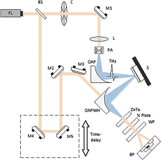
Figure 1 shows the schematic diagram of a typical THz-TDS instrument with reflection mode, which is usually adopted to carry out the inspection [15]. In brief, the light produced by the femtosecond laser (FL) is separated into an excitation beam and a probe beam by a beam splitter (BS). The excitation beam is used to pump a terahertz emitter antenna to generate a short pulse of broadband terahertz radiation. The generated terahertz pulse is focused on the sample, the reflection is detected using a terahertz receiver antenna, and the probe beam is passed through the time-delay device. Then it is processed by the balanced amplification photodetector (BP) to generate electrical signals for further data analysis by computer. In this work, measurement is performed using a commercial THz-TDS system, TeraPulse 4000 (TeraView Ltd., Cambridge, United Kingdom). The system works with a reflection imaging module (RIM), and the stable terahertz spectrum ranges from 0.1–4 THz. The diameter of the terahertz spot at the focal point is about 0.2 mm. The scanning step is set at 0.1 mm with the consideration of measurement effect and measurement speed, and it scans approximately 16 pixels per sec. The achieved signal-to-noise ratio can be up to 90 dB.

FIGURE 1. The schematic diagram of a typical THz-TDS instrument with reflection mode. FL: femtosecond laser; BS: beam splitter; M1, M2, M3, M4, and M5: plane mirror; C, chopper; L, lens; PA, photoconductive antenna; OAP, off-axis parabolic mirrors; OAPWH, off-axis parabolic mirror with hole; WP, Wollaston prism; BP, balanced amplification photodetector.
The organic protective coating system commonly consists of various functional paint layers. The anticorrosive primer paint which consists of resins and polyurethane, etc., is first sprayed onto the metal substrate; this is followed by a so-called “link-coat” which can provide a good connection with the adjacent paint layer; and the self-polishing antifouling paint is sprayed last to prevent attachment and growth of marine organisms. The test samples here are 1.5 cm * 1.5 cm in size. The refractive indexes of various paints are obtained by a terahertz wave test of samples with a single paint layer on the metal substrate. Sample 1 is sprayed with antifouling paint, Sample 2 is sprayed with the link-coat, and Sample 3 is sprayed with anticorrosion paint. The average thickness is firstly obtained using the traditional thickness meter. Then the time domain terahertz-wave signal (so called “TPI signal” here) is processed and the refractive index of paint npaint is calculated through the formula as follow:
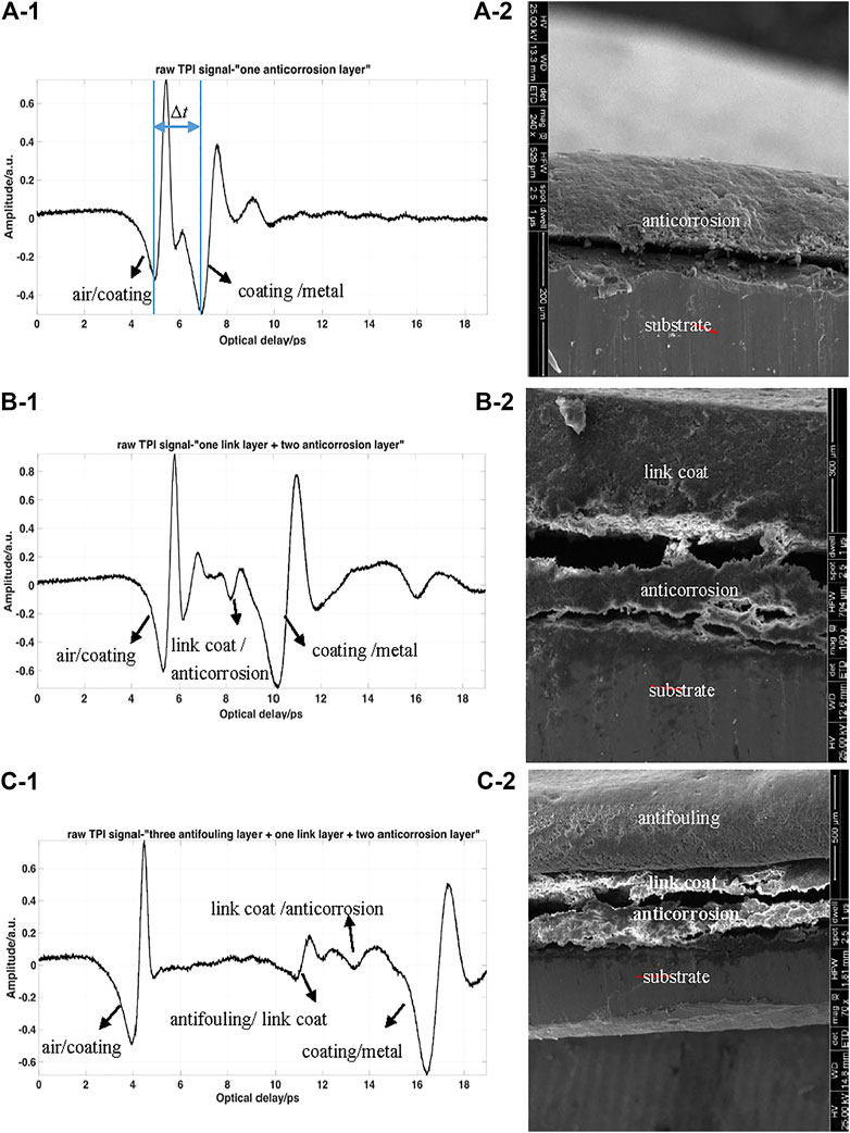
where d represents the measured thickness of the paint layer, c represents the speed of light in a vacuum, Δt is the time interval of two peaks aroused from the air/coating interface and coating/steel interface (as can be seen in Figure 2A), and α is the refractive angle and can be determined through npaint sinα = nair sinθ, where θ is the terahertz incident angle (it was set at 30° here). The results of refractive indexes are calculated and shown in Table 1.

FIGURE 2. TPI signal and SEM scan results of various coated samples (Ai), (Aii) Sample 4; (Bi), (Bii) Sample 5; (Ci), (Cii) Sample 6.
Monitoring the film thickness is an important part of coating quality control. An unqualified paint layer would lead to insufficient adhesion and poor protection functionality. On each sample, several points of the terahertz test result are selected to calculate thickness individually with the obtained refractive index. Table 1 also shows some TPI measured thickness results. The maximum variance of the threes samples is 6.46% (Sample 1), 7.73% (Sample 2), and 6.72% (Sample 3) when compared to the traditional thickness meter. It needs to be pointed out that the resolution of TPI is approximately 20–30 μm and it can meet the requirements of the painting process with the current technology for monitoring the thickness of single-layer and multilayered organic coatings using terahertz technology [7, 8].
Besides, Table 2 shows three different coating sample structures during the spraying process. It should be noted here that “sprayed layer order” in the table means the painting order of coatings. Sample 4 is one anticorrosion paint layer coated on the substrate, Sample 5 is one layer of “link-coat” + two anticorrosion paint layers coated on the substrate, and Sample 6 is three antifouling paint layers + one “link-coat” layer + two anticorrosion paint layers coated on the substrate.
Figures 2Ai,Bi,Ci show the TPI signals reflected back from the various coating systems. From the figures, the intensity of the reflective peak from the coating/metal interface is obviously strong due to the strong reflection of the metal substrate. And the peak reflected from the air/coating is also strong because their refractive indexes vary greatly. Besides, the peak arising from the antifouling/link-coat (as can be seen in Figure 2Ci) is easily distinguishable even though their variance is small. The results suggest that the terahertz wave has a good ability to distinguish various organic coating structures. It is verified with images taken using a scanning electron microscope (SEM) as shown in Figures 2Aii,Bii,Cii
Detection of Hidden Defects Beneath the Coatings
Another key issue is the reliable detection of defective coating structures, which directly affects the extensive use of terahertz non-destructive testing technology. During the corrosive deterioration process of protective coatings, the chemical and physical characteristics change and thus form various defects. There are several kinds of localized hidden defects beneath the coating: paint bulge defects, paint detachment defects, and metal corrosion. They would reduce the protective performance of the coating system. We, therefore, investigate terahertz detection of such kinds of defective samples.
The hidden corrosion defect is usually caused by two reasons: insufficient pre-treatment of the metal substrate surface before spraying which leads to residual oxide, rust, etc.exists; or the long-term seawater penetration during the serving time causes the chemical corrosion of metal. Figure 3 shows TPI testing results of the first kind of corrosion defective coating. The defective sample was sprayed with one anticorrosion layer with some rust retained on the metal surface before painting. Figure 3A shows the TPI signals of several points (1–8) of the sample in the x-direction. As shown in Figure 3B, the C-SLICE view represents the x-y plane of the sample (the coating surface). When terahertz wave testing the sample, each pixel of the image corresponds to the peak amplitude of the reflected terahertz pulse in the time domain. In Figure 3B, at the area marked “A” where hidden corrosion defects exist, it covers approximately 45 pixels in the horizontal axis (x-direction) and 25 pixels in the vertical axis (y-direction). Consequently, the defect sizes can be evaluated as 4.5 mm*2.5 mm. The TPI signals of points 4–6 (as can be seen from Figure 3A) represent some pixels of the defect position, where the difference can be easily distinguished when compared to the no defect area (point 2, 3, and 7). Figure 3C is the B-SLICE view the x-z plane of sample, where the horizontal axis represents the x-direction and the vertical axis represents the z-direction (depth direction). Furthermore, paint layer thickness can be further obtained by processing the scanned pixels using the method mentioned in the last section. The results suggested that if the improper pre-treatment of the substrate occurs in the painting process which then causes a small amount of corrosion, it can be quickly detected by TPI testing after the first sprayed order, and timely remedial measures could be taken to clean up the residual oxides on the substation. In addition, TPI is able to spatially obtain the painting uniformity distribution information from the 2D THz images (C-SLICE view and B-SLICE view).

FIGURE 3. TPI result of the “one anticorrosion paint layer + metal substrate” coating system with corrosion defects. (A) TPI signals of several points of the detected sample, (B) C-SLICE view of the detected sample, (C) B-SLICE view of the detected sample.
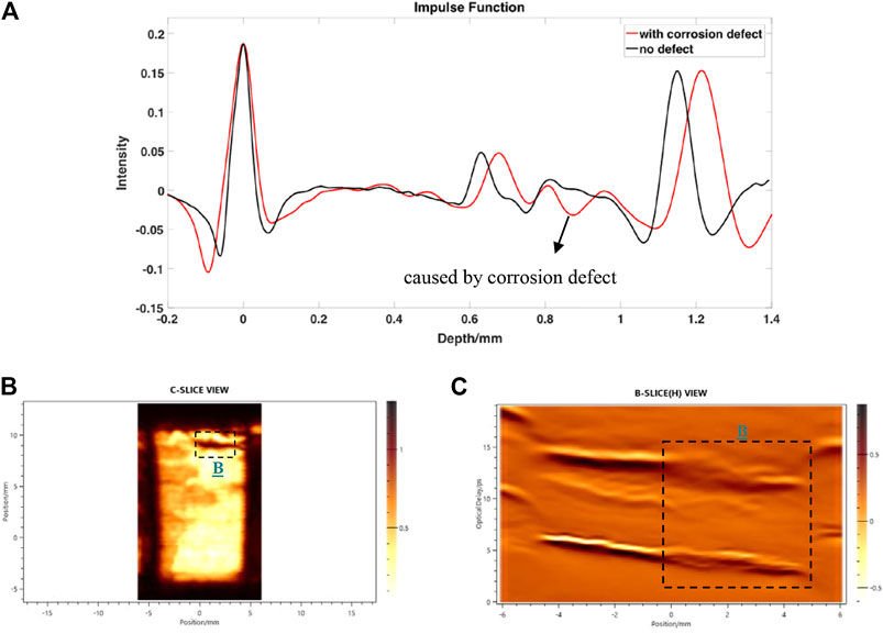
Another kind of hidden corrosion defect is also investigated and the terahertz testing results are shown in Figure 4. The defective sample has a corrosion defect set under the multilayered paint (three antifouling paint layers + one “link-coat” layer + two anticorrosion paint layers). Figure 4A is the comparison of impulse functions of the defective coating sample and the perfect one. Impulse function can be obtained from deconvolution performed by dividing the raw TPI signal of the experimental sample by a reference signal in the frequency domain [16].
where f(t) is the impulse function, g(t) is the raw TPI signal of sample, and h(t) is the reference signal which is collected from reflections from a metallic surface.

FIGURE 4. TPI result of the “three antifouling paint layer + one “link-coat” layer + two anticorrosion paint layer + metal substrate” coating system with corrosion defect. (A) Impulse function comparison of defective coating and the perfect one, (B) C-SLICE view of detected sample, (C) B-SLICE view of detected sample.
Here a double Gaussian band-pass filter is used as follows [17]:
where HF and LF are related to the upper and the lower cut-off frequencies of the filter, respectively. Here they are set as HF = 0.18 and LF = 1.05.
Obviously, the occurrence of metallic oxides on the substrate would reduce the paint layer uniformly, thus the detection result is more complex. Even so, the corrosion defect can also be distinguished from the TPI results. Furthermore, combined with the impulse function shown in Figure 4A, the corrosion defect beneath the coating could be quantitatively evaluated. Figures 4B,C are the C-SLICE view and B-SLICE view of the terahertz test results, respectively. In Figure 4B, at the area marked “B” where the hidden corrosion defect exists, it covers approximately 36 pixels in the horizontal axis and 11 pixels in the vertical axis, thus the defect size is about 3.6 mm*1.1 mm.
Beside the corrosion defect, paint bulge defects and paint detachment defects are also investigated. It is not easy to directly determine whether the separation occurs between the adjacent paint layers or the coating/metal interface by conventional techniques. However, defect type identification is important because it is related to the coating performance evaluation. It can be carried out by combining terahertz detection with the causes of defects.
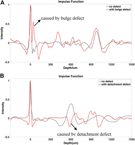
Figure 5 shows the TPI testing results of the paint bulge defect and paint detachment defect coating structure, respectively. For simplicity, the experimental samples are only coated with an anticorrosion paint and antifouling paint layer but without “link-coat.” Figure 5A is the impulse function of the TPI test of the coating system with the bulge defect. It suggests that the separation occurs within the antifouling paint layers and can be identified by type because the paint bulge is usually caused by long-term seawater penetration and leads to the separation phenomenon between the adjacent paint layers. On the other hand, Figure 5B is the impulse function of the TPI test of the coating system with the detachment defect between the coating and substrate. It is mainly caused by the fail of adhesion strength between the coating and metal substrate, usually due to aging deterioration. When the bulge defect or paint detachment defect occurs, it shows great similarity from the coating appearance, i.e., the coating blisters in a similar manner. With the TPI testing results, the two types of defect can be quickly and obviously distinguished and identified, which is helpful for further coating performance evaluations. To further characterize the defect size, the method mentioned in the previous section can be adopted.

FIGURE 5. Impulse functions of terahertz wave testing of various coating systems with paint separation. (A)With bulge defect, (B) with detachment defect.
Conclusion
This work presents research on terahertz non-destructive testing of multiplayer organic coating systems. Various types of coating structures, especially some defected samples, are measured and structural analysis is carried out in detail. Further quantitative analysis is performed through the analysis of several measurement points where the defect occurs. The hidden defects beneath the coating including corrosion, paint bulge, and paint detachment are investigated and defect identification is carried out by a combination of terahertz test results with the causes of defect. The results indicate that terahertz imaging has a good potential to test the multilayer organic protective coating system. Furthermore, for extending the application of terahertz technology, more effective methodology to improve the detection accuracy for minor defects is an important area for future work. It has important reference value for improving the failure prevention ability of large-scale components of engineering structures and has good engineering application prospects.
Data Availability Statement
The raw data supporting the conclusion of this article will be made available by the authors, without undue reservation.
Author Contributions
WT: validation, supervision, project administration. SZ: methodology, conceptualization and resources. WT and QZ: experiment, investigation. WT and ML: software, formal analysis. WL: data curation and visualization. WL: writing-original draft preparation. SZ, ML, and QZ: writing-review and editing. All authors have read and agreed to the published version of the manuscript.
Funding
We appreciated the support by the National Natural Science Foundation of China (grant number 51905102 and grant number 51675103); the Fujian Provincial Natural Science Foundation (grant number 2020J01683 and grant number 2019I0004); and the Jimei University National Fund Breeding Program (grant number 2P2020012).
Conflict of Interest
The authors declare that the research was conducted in the absence of any commercial or financial relationships that could be construed as a potential conflict of interest.
References
1. Wan H, Du C, Liu Z, Song D, Li X. The Effect of Hydrogen on Stress Corrosion Behavior of X65 Steel Welded Joint in Simulated Deep Sea Environment. Ocean Eng (2016) 114:216–23. doi:10.1016/j.oceaneng.2016.01.020
2. Oh J-W, Jung J-Y, Song K, Nam Y, Sung K-Y, Oh S, et al. Characteristics Analysis of the Developed Surface Modification Technologies to Improve the Anti-corrosion Performances for Offshore Equipments. J Mech Sci Technol (2019) 33(8):3971–9. doi:10.1007/s12206-019-0742-y
3. Nguyen Dang D, Peraudeau B, Cohendoz S, Mallarino S, Feaugas X, Touzain S. Effect of Mechanical Stresses on Epoxy Coating Ageing Approached by Electrochemical Impedance Spectroscopy Measurements. Electrochimica Acta (2014) 124(4):80–9. doi:10.1016/j.electacta.2013.08.111
4. Sun Y, Sy M, Wang J, Ahuja A, Pickwell E. A Promising Diagnostic Method: Terahertz Pulsed Imaging and Spectroscopy. Wjr (2011) 3(3):55. doi:10.4329/wjr.v3.i3.55
5. Cook D, Sharpe S. Terahertz Time Domain Measurements of marine Paint Thickness. Opt Terahertz Sci Technology (2007) 2007:TuB5. doi:10.1364/OTST.2007.TuB5
6. Jen C-Y, Richter C. Sample Thickness Measurement with THz-TDS: Resolution and Implications. J Infrared Milli Terahz Waves (2014) 35(10):840–59. doi:10.1007/s10762-014-0093-9
7. Cheng B, Ren J, Gu J, Li L, Gao T. High Precision Thickness Detection of Coatings Based on Terahertz Propagation Simulation Model. Acta Optic Sinica (2020) 40(13):80–6. doi:10.3788/AOS202040.1312001
8. Lin Y, Ming-Xia H, Lai H. Study on Terahertz Pulse Spectra Technology to Measure the Thickness of Micro-scale Multilayer Coatings. Chin Spectrosc Spectral Anal (2017) 37(11):3332–7. doi:10.3964/j.issn.1000-0593(2017)11-3332-06
9. Anastasi R, Madaras E. Terahertz NDE for under Paint Corrosion Detection and Evaluation. AIP Conf Proc (2006) 820(1):49–56. doi:10.1063/1.2184571
10. Kurabayashi T, Yodokawa S, Kosaka S. Terahertz Imaging through Paint Layers. 37th International Conference on Infrared, Millimeter, and Terahertz Waves. IRMMW-THz (2012). p. 1–2.
11. Norikazu F, Kiyonobu S. Non-destructive Terahertz Imaging of Alkali Products in Coated Steels with Cathodic Disbanding. Prog Org Coat (2019) 137(C):105334. doi:10.1016/j.porgcoat.2019.105334
12. Staats N-A, Stübling E-M, Portsteffen H, Koch M. Investigations into the Application of Terahertz Radiation as a Control Possibility for Paint Layer Consolidations. Stud Conservation (2020) 66:79–89. doi:10.1080/00393630.2020.1807789
13. Tu W, Zhong S, Shen Y, Incecik A, Fu X. Neural Network-Based Hybrid Signal Processing Approach for Resolving Thin Marine Protective Coating by Terahertz Pulsed Imaging. Ocean Eng (2019) 173:58–67. doi:10.1016/j.oceaneng.2018.12.051
14. Tu W, Zhong S, Shen Y, Incecik A. Nondestructive Testing of Marine Protective Coatings Using Terahertz Waves with Stationary Wavelet Transform. Ocean Eng (2016) 111:582–92. doi:10.1016/j.oceaneng.2015.11.028
15. Shen Y. Terahertz Time-Domain Spectroscopy and Imaging. J Electr Electron Syst (2013) 2013:e113. doi:10.4172/2332-0796.1000e113
16. Walker GC, Bowen JW, Labaune J, Jackson J-B, Hadjiloucas S, Roberts J, et al. Terahertz Deconvolution. Opt Express (2012) 20(25):27230–41. doi:10.1364/oe.20.027230
Keywords: terahertz pulsed imaging, defect identification, non-destructive testing, hidden defect, organic protective coating
Citation: Tu W, Zhong S, Luo M and Zhang Q (2021) Non-Destructive Evaluation of Hidden Defects Beneath the Multilayer Organic Protective Coatings Based on Terahertz Technology. Front. Phys. 9:676851. doi: 10.3389/fphy.2021.676851
Received: 06 March 2021; Accepted: 17 May 2021;
Published: 25 June 2021.
Edited by:
Xiaoyong Hu, Peking University, ChinaReviewed by:
Przemyslaw Lopato, West Pomeranian University of Technology, PolandQi Huixin, Peking University, China
Copyright © 2021 Tu, Zhong, Luo and Zhang. This is an open-access article distributed under the terms of the Creative Commons Attribution License (CC BY). The use, distribution or reproduction in other forums is permitted, provided the original author(s) and the copyright owner(s) are credited and that the original publication in this journal is cited, in accordance with accepted academic practice. No use, distribution or reproduction is permitted which does not comply with these terms.
*Correspondence: Wanli Tu, d2FubGl0dUAxNjMuY29t
 Wanli Tu
 Shuncong Zhong
 Manting Luo2
