- 1Spatial Computing Convergence Center, Kwangwoon University, Seoul, South Korea
- 2Department of Plasma Bio-Display, Kwangwoon University, Seoul, South Korea
- 3Graduate School of Smart Convergence, Kwangwoon University, Seoul, South Korea
- 4Ingenium College, Kwangwoon University, Seoul, South Korea
Modern Pepper's ghost—“floating hologram”—systems generally use transparent screens called half mirrors or foils. this system must have the same screen size as the image size in order to display a large-sized image. Further, depth of the image can only be obtained from the distance between the screen and the display panel. These limitations can be overcome using holographic optical elements (HOE). HOE is made by recording as a refractive force of the lens with holographic material. In this study, the numerical values of the reconstructed images were theoretically analyzed through optical ray tracing, and the theoretical design of the reconstructed image size and depth plane was numerically measured and experimentally verified.
1. Introduction
There are several 3D displays that their developers claim to be “holographic” [1]. In particular the modern versions of the Pepper's ghost illusion—invented by the English scientist John Henry Pepper in 1862—are often call “floating holograms” by the general public and the media. Pepper's ghost technique displays 2D images on the reflector to create the effect of floating virtual 3D images for the viewers [2–4]. The system typically uses transparent screens called half mirrors or foils as a way to project 2D images in the space. This system has a 1:1 ratio of the size of input and output images, and the depth takes place near the screen. This limits expressing flotation and depth. To solve this problem, a holographic optical element (HOE) can be used as a screen. Projecting a 2D image using HOE enables the determination of the size and depth of the image by the lens equation given in Equation (1) [5–9]. Here, do represents the object distance, di represents the image distance, and f represents the focal distance of the lens [10–12].
This can change the 2D projection image displayed on the conjunctive surface using HOE. The HOE can operate a screen with the refractive force of the lens. Thus, the observer can see an augmented virtual image by the other side of the HOE, and this displayed image represents a magnified image in a deeper depth plane [13–16]. In this study, It is constructed using off-axis holographic techniques that lens objects used. We set the reference light to plane wave to ensure that HOE which has the function of the lens whit the correct focal distance. Thus, amplitude is 1, phase is zero, and incident angle is θ. Reference light has the following equation on the hologram plan given in Equation (2).
Therefore, the off-axis hologram can be expressed given in Equation (3).
If the reference beam is illuminated as recorded in this off-axis hologram, the image is reconstructed as shown given in Equation (4).
The first term is direct light and is called DC term. The second term is object light, which in the case of HOE is light that functions as a lens. The third term is the conjugate light, which proceeds approximately in 2θ direction. Because of exp(i2kx sin θ) ≈ exp(ikx sin 2θ) [17–19]. Therefore, HOE is equivalent to applying the refractive function of a lens to a hologram medium by positioning and recording the lens instead of the actual object in the conventional hologram method.
2. Materials and Methods
2.1. Optical Design Based on Ray Tracing
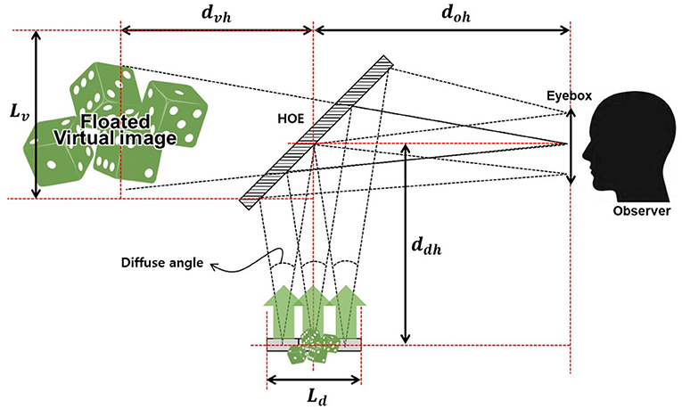
HOE is an optical element that records the interference patterns of the reference light and object's light on the photosensitive material [20]. While illuminating the reference light after recording, illumining the object light under the same conditions as the recorded reference light can work as lenses. Figure 1 is a schematic diagram of the augmented 3D display system using HOE [21, 22].
This hologram system with HOE utilizes displayed 2D images that are 150 × 150 mm size of the diffused projected image as a source. The diffused image distributes each source point to create an in-place light path of the reference beam used to record the HOE. The light sources of this image are transmitted through the HOE to gather at a specific distance to create one image. As such, HOE can replace the role of a non-spherical concave mirror. If this display system design is applied with several approximation caused by the replacement of thin films, the design of a system capable of observing high depth and magnified augmented 3D images is possible as a small volume optical system.
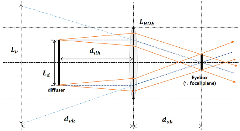
Figure 2 can show that equivalent model of the HOE display system represents the relationship between parameters approximately. Through this model, we know that how the distance between diffuser plate and HOE varies depending on the focal distance of the HOE. As we can see from the equivalent model, the lens focal distance is eventually set to a position similar to the position of eye-box, and the diffuser must be placed near the lens's focal point in order to display the 3D visual image.
3. Results and Discussion
3.1. The Definition for Value of System Components
HOE calculates the maximum angle of diffusion in an optical diffuser and has the size that all diffused rays can be inputted into HOE. If the optical diffuser is too far away from the HOE, the amount of light is decreased because the HOE does not accept all the light from the optical diffuser. On the other hand, if the optical diffuser is too close to the HOE, it is difficult for observers to see a virtual image because size of the eye-box is also decreased. In Figure 1, Lv is the length of one axis of the augmented virtual image on the HOE. Ld is the length of a single axis of the 2D projection image that is imaged on an optical diffuser. ddh is the distance from the optical diffuser to the HOE. doh is the distance from the observer's eye-box to HOE, and dvh represents the distance from HOE to augmented virtual image. However, there are two assumptions here, the first is that HOE can be approximated with thin lenses, and the second is that there is no spherical difference. Under these assumptions, an eye box is formed near the HOE focal plane considering the central ray. Strictly, the eye box does not exactly form on the focal plane, but this numerical differences that do not interfere with the visual display can be ignored. Using these assumptions and basic lens equations, we can create several equations that can be applied to the proposed system. do represents dvh as the object distance, but the reference light direction (+) in accordance with the lens convention results in do = −dvh because the opposite side of the lens is (-). This allows the equation for fHOE to be summarized as . This organized equation can be used to represent it as . Assuming that HOE is approximated by a thin lens, the distance doh from the eye-box to HOE of the observer is fHOE. Therefore, Ld can be represented as doh : Ld = dvh : Lv proportional to the distance doh from the observer's eye-box to HOE and the distance dvh from HOE to the virtual image. Therefore, the size of the virtual image represented by one axis length of the Augmented virtual image from HOE can be obtained from the Equation (2) as below.
3.2. Analysis of Reconstructed Holographic Image
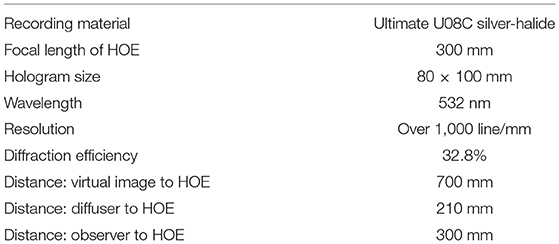
Using the HOE of the transparent film has the advantage of allowing the observer to observe the reality mixed with the external environment and augmented reality (AR) images. The parameters of the entire system using HOE are shown in Table 1.
We used U08C of silver halide film from ULTIMATE in this system. because it has excellent reconstruction properties for collars and is also capable of high-resolution representations [23, 24]. The HOE used a reflective holography recording method, a lens with a focal distance of 700 mm as an object beam, and the reference beam was recorded at a distance of 300 mm using a point light source. The target specification was to reconstruct the 350 × 350 mm sized augmented virtual image at a distance of 700 mm from the HOE. We numerically calculated the optical design for the size of the initial image displayed on the diffuser designed for it, the distance from the diffuser to the HOE, and the distance from the observer to the HOE. By calculating these three parameters and substituting them, the size and depth of the virtual images were obtained. It can be seen that the position on the eye box viewed by the observer is the same as the position of the focal distance of the HOE lens, and when there is an illusion at an infinite depth, the position of the diffusion plate is the same as the focal distance. Therefore, the position of the diffuser should be set up on the eye box. The focal distance of the lens and the distance from the HOE to the diffuser are derived using the lens manufacturer's formula. According to the lens manufacturer's formula shown in Equation (1), the distance between the diffusion plate and the HOE is calculated to be 210 mm. Thus, do is 210 mm, and do is −700 mm if the virtual image appears at a distance of 700 mm. Solving the equation, focal length of HOE comes out to be 300 mm. Therefore, the focal length of the HOE should be 300 mm. The diffuser consisted a diffusing film with a diffusing angle of 10° in a 200 × 200 mm sheet. The size of the image to be imaged in the diffuser determines the size of the virtual image at a distance of 700 mm and can be defined by Equation (5) from the proportional expression using light tracing from the HOE.
Figure 3A shows camera focusing at a distance of 210 mm when the image is displayed using half-mirror, and Figure 3B shows the displayed image when camera focusing is at a distance of 700 mm. The half-mirror of the system does not operate as a lens, so it just displayed without magnification and image depth is also same as a distance between diffuser and half-mirror. Unlike half-mirrors, the proposed system using HOE which used holography to produce refractive power is able to display magnified images at a deeper depth. Figure 3C is the reconstructed image after focusing the camera at a distance of 700 mm in the proposed system and Figure 3D is the reconstructed image after focusing on 210 mm. This proves that the image is reconstructed at a depth of 700 mm as a 350 mm size of image which is magnified about 2.3times. In this research, we analyzed numerically and produced the self-reflection force of the screen using HOE screens recorded by holographic methods. It's a different method than the previous general half-mirror display system. This not only has the advantage of minimizing the volume of typical systems, but also offers observers with large AR images augmented at a comfortable depth without composition of complex and massive systems.
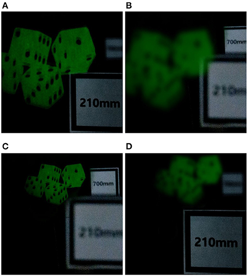
Figure 3. Virtual images from augmented 3D image display system. (A) Focused 2D projected images at 210 mm on the general system. (B) Defocused 2D projected images at 700 mm on the general system. (C) Focused 2D reconstructed images at 700 mm on proposed system with HOE. (D) Defocused 2D reconstructed images at 210 mm on proposed system with HOE.
Although the reconstruction plane is accurately calculated and displayed, there is one problem to be solved in this system. Even if Image inputted as off-axis is recorded on the medium to match the signal entering„ the quality of reconstruction image is reduced because off-axis display has still astigmatism. In the case of Figure 4A below, spot diagram was simulated according to the zero, 30 and 45° angle inputs at the focal plane of the output. Generally, we can say that the RMS error allowed in the image of distortion in the typical spot diagram of the projector's optical system is up to 7–8%, and it also that there is no issue to recognize reconstructed image from human eye [25]. As we can be seen in Figure 4A, the spot diagram at the focal plane, which is reproduced at an angle of incidence from 0 to 35°, satisfies this within 5%. However, the spot diagram in the focal plane, which reconstructed at an angle of 45° is 11% less than satisfactory value. Figure 4B can be simulated to determine Astigmatism difference. As images are display as near focus plane by off-axis input, we can see that the results for reconstructed images has the difference focal plane at 45° and it has difference of ~80 um in minus direction. The distortion curve can also be found to have the biggest error curve in the image by a 45° of input image.
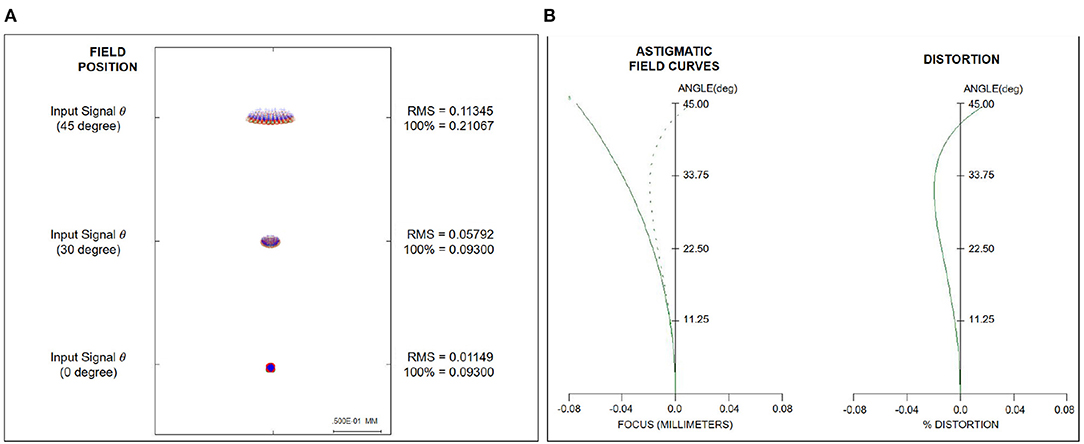
Figure 4. Aberration analysis for off-axis signals using optical simulation. (A) Spot-diagram in the focal plane of HOE for Off-axis signal input. (B) Analysis of astigmatism in the focal plane of HOE for Off-axis signal input.
4. Conclusion
In this research, we proposed a new display system using HOE with a refractive function fabricated using holography in conventional floating hologram techniques that can be displayed with simple light-paths. In traditional displays case, it is 1:1 ratio displays with the size of the screen being the same as well as the depth of the image being the same as the distance between the source and the screen. Therefore, there was no other way than to expand the volume of the system to implement a user-friendly eye depth and a large screen. However, if we use refractive power of the lens using holography, it is not necessary to fabricate elements, such as non-spherical lenses or diffractive optical elements(DOE). from this work, source images entering Off-axis at an angle of 45° were re-imaged using one HOE and resulting in 150 mm of source images expanding to a size of 350 mm, as well as the depth of the images overlapped with real-world making it easier for users to see. In addition, it proved that simplified method using an equivalent model was proposed to enable users to implement a minimum resolution to view AR images through simulation. The loss of amplitude and phase was minimized by using the HOE of the display using Off-axis as a signal. It is true that there are several problems to be improved, such as aberration from off-axis and diffraction efficiency form hologram material. In the future, if various ways to solve aberration and display high luminance are presented, it is expected that AR display industry will be able to use it in various fields, such as AR-glass, head-up display (HUD), and mobile AR cameras.
Data Availability Statement
The original contributions presented in the study are included in the article/supplementary material, further inquiries can be directed to the corresponding author/s.
Author Contributions
SH and LH: specifically and conceptualization. SL: methodology. PG: formal analysis. JL and SK: validation. All the authors have made a substantial contributions regarding the conception and design of the work, and the acquisition, analysis and interpretation of the data, read, and agreed to the published version of the manuscript.
Funding
This research was supported by the Ministry of Science and ICT (MSIT), Korea, under the Information Technology Research Center (ITRC) support program (IITP-2021-2015-0-00448 and IITP-2020-01846) supervised by the Institute of Information & Communications, Technology, Planning, & Evaluation (IITP). This research was supported by Institute of Information & Communications Technology Planning & Evaluation (IITP) grant funded by the Korea Government (MSIT) (No. 2021-0-00922, Development of holographic stereogram printing technology based on multi-view imaging).
Conflict of Interest
The authors declare that the research was conducted in the absence of any commercial or financial relationships that could be construed as a potential conflict of interest.
References
1. Brooker J. Pepper's ghost, metempsychosis and the magic lantern at the Royal Polytechnic Institution. Early Pop Vis Cult. (2007) 5:189–206. doi: 10.1080/17460650701433517
2. Sanjay K, Kevin M, Vincent T, Izabela N, Tomoyoshi SM. Development of a photopolymer holographic lens for collimation of light from a green light-emitting diode. Appl Opt. (2018) 59:8029–37. doi: 10.1364/AO.57.00E163
3. Hoda A, Izabela N, Suzanne M. Using acrylamide-based photopolymers for fabrication of holographic optical elements in solar energy applications. Appl Opt. (2014) 53:1343–53. doi: 10.1364/AO.53.001343
4. Koreshev SN, Shevtsov MK. Holographic sight of the light-guide type with a synthesized pupil. J Opt Technol. (2018) 85:153–6. doi: 10.1364/JOT.85.000153
5. Zhiqin H, Daniel LM, David RS. Polarization-selective waveguide holography in the visible spectrum. Opt Express. (2019) 27:35631–45. doi: 10.1364/OE.27.035631
6. Wei Z, Dan LX, Guo. Optical design and optimization of a micro zoom system with liquid lenses. Opt Soc Korea. (2013) 177:447–53. doi: 10.3807/JOSK.2013.17.5.447
7. Mert S, Hulya K. Optical beam-shaping design based on aspherical lenses for circularization. Appl Opt. (2008) 47:230–41. doi: 10.1364/AO.47.000230
8. Chen YC, Nian SC, Huang MS. Optical design of the Fresnel lens for LED-driven flashlight. Appl Opt. (2016) 55:712–21. doi: 10.1364/AO.55.000712
9. Bang KS, Jang CW, Lee BH. Curved holographic optical elements and applications for curved see-through displays. J Inform Display. (2019) 20:9–23. doi: 10.1080/15980316.2019.1570978
10. Bieren KV. Lens design for optical Fourier transform systems. Appl Opt. (1971) 10:2739–42. doi: 10.1364/AO.10.002739
11. Wei SL, Fan ZC, Zhu ZB, Ma DL. Design of a head-up display based on freeform reflective systems for automotive applications. Appl Opt. (2019) 58:1675–87. doi: 10.1364/AO.58.001675
12. Craig TD, Colton MB, Micah SM, Kalluri S, Pierre-Alexandre B. Holographic waveguide head-up display with 2-D pupil expansion and longitudinal image magnification. Appl Opt. (2019) 58:A251–7. doi: 10.1364/AO.58.00A251
13. Piao JA, Li G, Piao ML, Kim N. Full color holographic optical element fabrication for waveguide-type head mounted display using photopolymer. J Opt Soc Korea. (2013) 17:242–8. doi: 10.3807/JOSK.2013.17.3.242
14. Hiroshi A, Yasuyuki I, Takashi K, Koki W, Hiroshi H, Rintaro M, et al. Reconstruction of a three-dimensional color-video of a point-cloud object using the projection-type holographic display with a holographic optical element. Opt Express. (2020) 28:5692–705. doi: 10.1364/OE.387072
15. Koreshev SN, Shevtsov MK. Optical systems of holographic collimator sights. J Opt Technol. (2015) 82:592–7. doi: 10.1364/JOT.82.000592
16. Chen Z, Sang X, Li H, Wang Y, Zhao L. Ultra-lightweight and wide field of view augmented reality virtual retina display based on optical fiber projector and volume holographic lens. Chin Opt Lett. (2019) 17:090901. doi: 10.3788/COL201917.090901
17. Etienne C, Pierre M, Christian D. Spatial filtering for zero-order and twin-image elimination in digital off-axis holography. Appl Opt. (2000) 39:4070–5. doi: 10.1364/AO.39.004070
19. Ting-Chung P. Optical scanning holography—a review of recent progress. J Opt Soc Korea. (2009) 13:406–15. doi: 10.3807/JOSK.2009.13.4.406
20. Christophe M, Vladimir K, Basile M, Daivid F. See-through holographic retinal projection display concept. Optica. (2018) 5:1200–9. doi: 10.1364/OPTICA.5.001200
21. Yves G, Philippe G. CHIMERA, a new holoprinter technology combining low-power continuous lasers and fast printing. Appl Opt. (2019) 58:G226–30. doi: 10.1364/AO.58.00G226
22. Fernandez R, Bleda S, Gallego S, Neipp C, Marquez A, Belendez A. Holographic waveguides in photopolymers. Opt Express. (2019) 27:827–40. doi: 10.1364/OE.27.000827
23. Gentet P, Gentet Y, Lee SH. Ultimate 04 the new reference for ultra-realistic color holography. In: Proceedings of the Emerging Trends Innovation in ICT (ICEI) (2017), International Conference on IEEE, Yashada, Pune (2017). p. 162–6.
24. Brooker J. New LED's wavelengths improve drastically the quality of illumination of pulsed digital holograms. In: Proceedings of the Digital Holography and Three-Dimensional Imaging (2017), JeJu Island (2017). p. 209.
Keywords: augmented reality, projection display, 3D imaging, hologram, holographic optical element
Citation: Ha S, Hwang L, Lee J, Gentet P, Kwon S and Lee S (2021) A Study on Augmented 3D Display Optimization Based on Holographic Optical Element for High Depth and Magnified Image. Front. Phys. 9:663122. doi: 10.3389/fphy.2021.663122
Received: 02 February 2021; Accepted: 09 April 2021;
Published: 10 May 2021.
Edited by:
Yanpeng Zhang, Xi'an Jiaotong University, ChinaReviewed by:
Junsuk Rho, Pohang University of Science and Technology, South KoreaJacopo Parravicini, University of Florence, Italy
Copyright © 2021 Ha, Hwang, Lee, Gentet, Kwon and Lee. This is an open-access article distributed under the terms of the Creative Commons Attribution License (CC BY). The use, distribution or reproduction in other forums is permitted, provided the original author(s) and the copyright owner(s) are credited and that the original publication in this journal is cited, in accordance with accepted academic practice. No use, distribution or reproduction is permitted which does not comply with these terms.
*Correspondence: Seunghyun Lee, c2hsZWVAa3cuYWMua3I=
 Sungjae Ha
 Leehwan Hwang
 Jaehyun Lee2
 Philippe Gentet