
95% of researchers rate our articles as excellent or good
Learn more about the work of our research integrity team to safeguard the quality of each article we publish.
Find out more
ORIGINAL RESEARCH article
Front. Phys. , 29 April 2021
Sec. Optics and Photonics
Volume 9 - 2021 | https://doi.org/10.3389/fphy.2021.651898
This article is part of the Research Topic Tunable and Reconfigurable Optical Metamaterials View all 11 articles
 Yongkang Song1
 Weici Liu2Xiaolei Wang3
 Faqiang Wang1*Zhongchao Wei1Hongyun Meng1Ning Lin1Hongqiang Zhang1
Metasurfaces have powerful light field manipulation capabilities, which have been extensively studied in the past few years and have developed rapidly in various fields. At present, the focus of metasurface research has shifted to the tunable functionality. In this paper, a temperature-controllable multifunctional metasurface lens based on phase transition material is designed. First of all, by controlling the temperature of the desired working area and the polarization of the incident light, switching among multiple focus, single focus, and no focus at any position can be achieved, and the intensity and helicity of the output light can be adjusted. In addition, a polarization-sensitive intensity-tunable metalens based on the P-B phase principle is designed, when the incident light is linearly polarized light, left-handed circularly polarized light, or right-handed circularly polarized light, it has the same focal point but with different light field intensities. Therefore, the focused intensity can be tunable by the polarization state of the incident light.
Metasurfaces, the corresponding two-dimensional metamaterials, can flexibly control the amplitude, phase, and polarization of light through sub-wavelength units, compared with the traditional lens that relies on the modulated light beam to accumulates the phase delay during the transmission, it is smaller in size, lighter in weight, and suitable for device miniaturization and system integration. Thanks to the special properties of metasurfaces, various new applications can be realized, such as hologram [1–4], polarization measurement [5–7], vortex beam generator [8, 9], non-linear dynamics [10–12], beam shaping, etc. [13, 14].
The bifocal and multifocal lenses that can focus on different positions can be used in imaging systems [15, 16], optical communication [17, 18], and medical applications [19], etc. Previous studies have also used Pancharatnam-Berry (P-B) phase metasurface to achieve multi-focus focusing function [15, 20]. However, their work has some limitations: firstly, once the lens structure is produced, its function cannot be changed; secondly, based on the principle of P-B phase modulation, it demands higher requirements of the helicity of the incident light. Usually, the requirement is circular-polarized incident light, and polarization-independent focusing cannot be achieved.
Phase transition materials are a good choice to provide a wide range of tunable metamaterials, whose electronic properties can be tuned in real time during structural phase transitions. By using phase transition materials, the optical response of metamaterials can be significantly adjusted by external excitations [21]. Currently, the common phase transition materials used in metasurfaces are Ge2Se2Te5 [22, 23], vanadium dioxide (VO2) [24], or graphene [25], etc. In terms of thermal control materials, vanadium dioxide has the capability of insulating-metal phase transition, and its structure can change reversibly with temperature. Its phase transition temperature is TC = 68°. When temperature is below the phase transition temperature TC, it exhibits a monoclinic phase structure, in a semiconductor insulation state (I-VO2), the infrared transmittance is higher at this state; When temperature is higher than the phase transition temperature TC, it presents a rutile tetragonal phase structure, in a metallic state (M-VO2), and has a lower infrared transmittance [26–28]. In recent years, there have been many studies on metasurfaces based on vanadium dioxide, including controlling temperature or heat flux [29, 30], asymmetric transmission [31], switchable focus lens [32–34], switchable wave-plates [35], beam control [36], and the like. However, most of these designs can only achieve fixed function, or only work under a specific condition [37].
In this article, we propose a temperature-controllable metalens based on VO2 material working in the mid-infrared band. By controlling the temperature, the conversions among bifocal, single focus, and no focus can be realized, and the helicity of the focal light is changable, as shown in Figure 1. In addition, based on the principle of P-B phase, the co-focal lens which works for linear polarized light, left-handed circularly polarized light, and right-handed circularly polarized light is designed, and the intensity of the focal spot is different for different incident polarized light. Thus, a polarization sensitive lens with tunable intensity is realized.
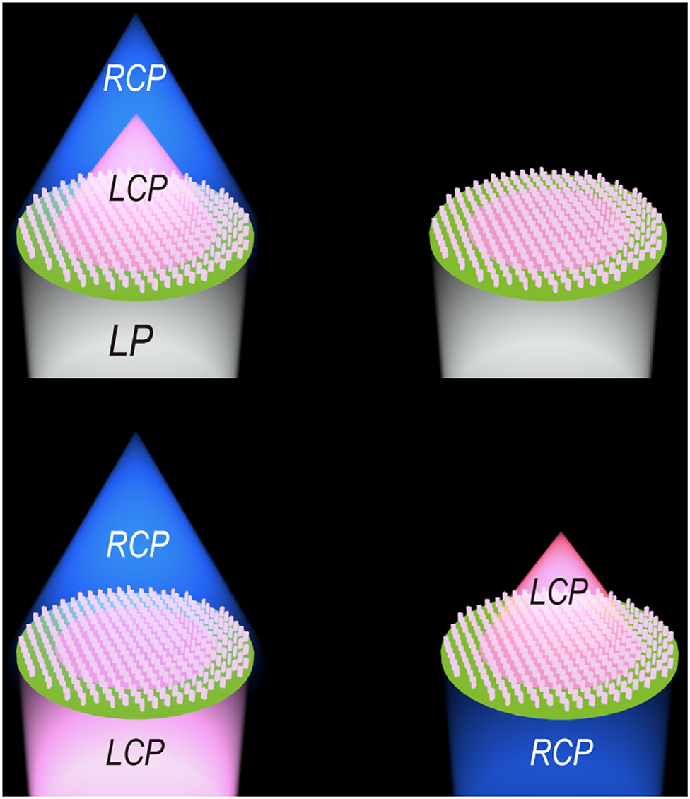
Figure 1. Working principle diagram. The two pictures on the top show the wavefront reshaping pictures at different temperatures when LP light is incident, and the two pictures on the bottom are the wavefront reshaping pictures under LCP and RCP light incidents.
More importantly, we showed a multifunctional lens made of thermally controlled phase transition materials, and provided a new design method for adjustable multifocal lenses. As an extension, other phase transition materials and different control methods, such as electric control, can also be used to complete focus switchable, polarization independent metasurface lenses.
Based on the vanadium dioxide material, the conductor model parameter is used below the phase transition temperature TC (when in I-VO2), corresponding permittivity ε = 9 [38]. When temperature is higher than the phase transition temperature TC (at M-VO2), the Drude model is used to determine the parameters.
The complex permittivity of vanadium dioxide can be given by the following dispersion relation [39–41]:
Among them, the first item represents ultimate high frequency permittivity, ε∞ = 12; represents the collision frequency, here m* is the optical effective mass of electrons. ωn(σ) represents electrical conductivity, which is related to plasma frequency. Because σ are directly proportional to the free carrier density; According to the reference, it can be known as .
Figure 2 shows the transmittance properties of VO2 film [40]. The two curves in Figure 2A represent the change of transmittance in the frequency range of 0.25–5eV when the temperature is 300 K and 355 K, respectively. We can get that when the temperature of the VO2 film is 300 K and 355 K, the transmittance of 0.31 eV (4 μm) incident light shows a huge contrast. The red and blue curves in Figure 2B show the transmittance of VO2 film (at 4 μm) between heating and cooling, respectively. It can be seen from the figure that there is a short temperature change interval within which the transmittance changes rapidly with temperature, and the change is reversible. Outside the corresponding temperature in the phase transition zone, the transmittance is relatively stable.
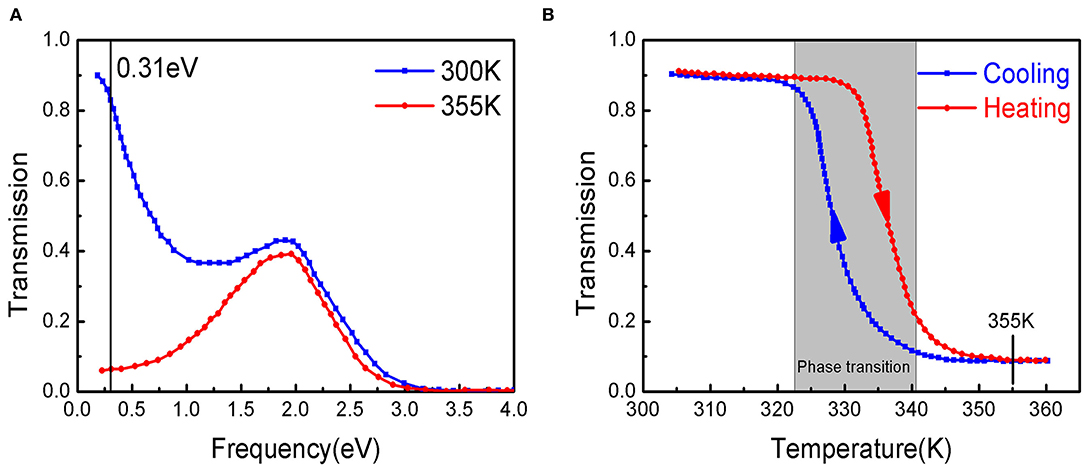
Figure 2. Transmittance properties of VO2 film (100 nm) [40]. (A) The bi-phase transmittance of VO2 film in the frequency range of 0.25 eV–5 eV. (B) Transmittance changes with temperature during cooling and heating of VO2 film at 4 μm.
In summary, the transmittance of the VO2 film at 4 μm changes drastically in the phase transition interval, and the heating and cooling process is reversible. Therefore, it can exhibit stable performance outside the phase change region.
According to the P-B phase modulation principle, The electric field generated by an incident plane wave of arbitrary polarization passing through the lens can be expressed as [42]:
In the formula, ηE, ηR, ηL represents the polarization level coupling efficiency, which can be expressed as:
Among them, tx, ty, respectively, represent the real amplitude transmission coefficients perpendicular and parallel to the optical axis, and ϕ represent the phase delay between the two polarizations. Symbols 〈Ein|L〉(〈Ein|R〉) denote the dot product of the incident polarized plane wave |Ein〉 and left-handed circularly polarized plane wave |L〉 (right-handed circularly polarized plane wave |R〉).
From the above formula, we can get that the outgoing electric field contains three components. The first component maintains the original polarization and phase of the incident beam; the second term is right-handed circular polarization with 2θ(x, y) phase modulation; The last term is opposite to the previous term which is left-hand circular polarization light with a modulation phase of −2θ(x, y).
For a special case: tx = ty, ϕ = π, when the left-handed circularly polarized light is incident, the outgoing beam will undergo full polarization conversion:
It can be seen from the above formula that the phase modulation depends on the local orientation of the sub-wavelength grating.
In the design of this article, glass is used as the substrate, and vanadium dioxide (VO2) is used for the structural unit. We control the changing of temperature so that it undergoes a mutual conversion from I-VO2 state to M-VO2 state. In order to achieve the purpose of lens focusing, the unit cell at different positions (x, y) need to meet the phase condition [43]:
Here, λin is the desired wavelength, f is the focal length, and (x0, y0) is the initial position of the focus. Based on the Equation (6), the unit cell at different positions (x, y) need to meet θ = ±φ/2 to ensure that the left-handed circularly polarized light or the right-handed circularly polarized light can pass through the structure and is converted into the opposite direction of rotation [44]. The rotation angle is:
Figure 3A is a schematic diagram of the structure. The lens is composed of two areas, A and B, which are a circle in the area (0, r1) and a ring in the area (r1, r2). Figure 3B is a schematic diagram of lens focusing when linearly polarized light is incident, and two focal points are formed. Figures 3C–E are perspective view, front view, and top view, respectively. We used a commercial three-dimensional (3D) finite-difference time-domain (FDTD) solver (FDTD solutions, Lumerical Inc.) to simulate the unit in the frequency domain with periodic boundary conditions in the x and y directions, and a perfectly matched layer in the z direction. By optimizing the structure, we determine that the incident wavelength λin = 4 μm, the period of each unit cell is P = 2.8 μm, and the height of the structural unit H = 3.2 μm. Scanning the phase change and transmittance of different circular polarizations light in I-VO2 and M-VO2 to determine the best choice of length and width. Figure 4A is a scan diagram of the phase delay varying with the length and width, Figures 4B,C are the schematic diagrams of the transmittance varying with the length and width in the two states of I-VO2 and M-VO2, respectively.
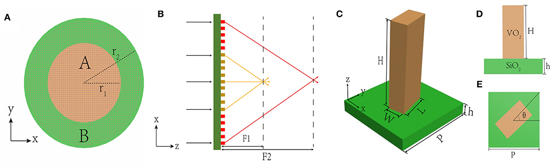
Figure 3. (A) Schematic diagram of the lens structure, composed of two areas A and B. (B) A schematic diagram of linearly polarized light focusing along the z direction after passing through the lens. (C) Schematic of the building block, The metalens consists of VO2 nanofins on a glass substrate. (D,E) Side and top views of the unit cell showing height H, width W, and length L of the nanofin, with unit cell dimensions P × P. The required phase is imparted by rotation of the nanofin by an angle θ, according to the geometric Pancharatnam-Berry phase.
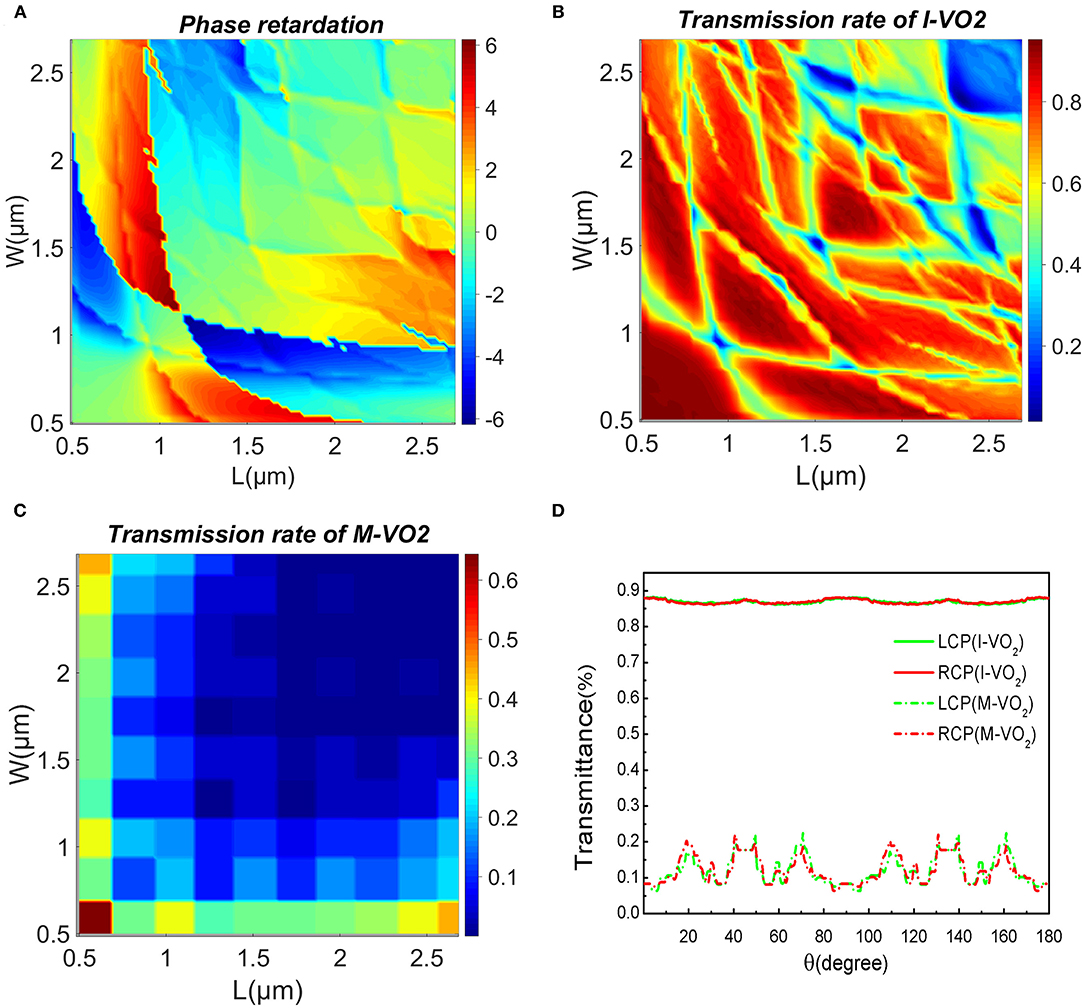
Figure 4. (A) Phase shift corresponding to each unit with different L and W at the state of I-VO2. (B) and (C) represent the scan graph of the transmittance of each unit in the I-VO2 and M-VO2 states as a function of L and W, respectively. (D) When the unit cell rotation angle is changed from 0 to 180°, the transmittance change graph corresponding to the incidence of LCP and RCP.
We choose the appropriate length and width to make the I-VO2 nanorods in the state of a half-wave plate, that is, the phase retardation ϕ = π, tx = ty, and the transmittance is as high as possible in the I-VO2 state, on the contrary, the transmittance is as low as possible in the M-VO2 state. Through scanning optimization and data analysis, we choose the length L = 1.25 μm and the width W = 0.75 μm of the VO2 structural unit.
In order to verify the feasibility of the lens, we observe the changes in the transmittance of the corresponding I-VO2 and M-VO2 under different polarized light incidence when the rotation angle of the unit cell changes from 0 to π. It can be seen from Figure 4D that the transmittance of I-VO2 always remains at about 0.88, whether the incident light is left-handed circularly polarized light or right-handed circularly polarized light, while the transmittance of M-VO2 varies between 0 and 0.2, It is in line with the situation that the transmittance of I-VO2 is much greater than that of M-VO2.
Here, we design a kind of adjustable lens that realizes multi-focus, single-focus, and non-focus conversion by incident different polarized light (LP, LCP, RCP) and temperature control. The lens consists of two areas, (0, r1) area A, and (r1, r2) area B, respectively, focusing on the incident light of RCP and LCP, as shown in Figures 2A,B. Here, the radius of the lens are set as r1 = 50.4 μm, r2 = 92.4 μm. The conditions for the rotation angles of the structural unit in the two regions are as follows:
Here, fA, fB are the focal lengths of the two areas A and B, respectively.
Without loss of generality, we set fA = 30μm, fB = 60μm as an example. When the temperature is lower than TC, the two areas A and B are both in I-VO2 state (pass state), which can maintain high transmittance. As we all know, LP can be regarded as a combination of LCP and RCP of equal amplitude. Linearly polarized light will form two focal points with focal lengths fA and fB after passing through the metalens, as shown in Figure 5A. The helicity of fA and fB is RCP and LCP, respectively, so as to realize dual focus focusing. When the temperature is higher than TC, the two regions A and B are in the M-VO2 state (close state), as shown in Figure 5B, no focus is formed at this time.
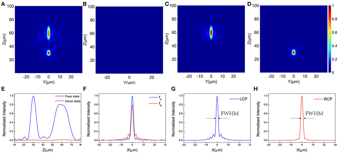
Figure 5. (A–D) The intensity profiles(y-z plane)of the metalens designed at the state of (A) for x-polarized incident light in the pass state, (B) for x-polarized incident light in the close state, (C) for LCP polarization incidence in the B pass state, (D) for RCP polarization incidence in the A pass state, (E) Normalized electric field intensity distribution along the z-axis for the two cases (A,B). (F) Corresponding to the horizontal cut of the two focal points fA and fB in (A), the width FWHM at half the maximum height is 2.53 μm and 2.15 μm. (G,H) represent the normalized electric field intensity graph under the incidence of LCP and RCP, respectively, and the corresponding FWHMs are 2.17 μm and 2.39 μm, respectively.
Figure 5E is a schematic diagram of the normalized electric field intensity along the z-axis in the above two cases. It can be seen from the figure that the intensity of the light field at the focal point in the passing state is much greater than the intensity in the closed state. In contrast, the intensity at high temperatures can be approximately ignored. The focal depth at f 2 = 60 μm is longer. This is because the NA at the two focal points are different, and the focal plane size is different, which results in different intensity distributions. Large depth of focus, has great advantages in many fields such as microscopes, endoscopes, inspection cameras, etc. [45].
In addition, we control the two regions A and B to result in different states. As for the isolation of the states of the VO2 materials in area A and area B, a thin insulating material can be added between the area A and the area B to avoid heat conduction. Both active heating and passive heating can achieve. Our cell structure is on the micron scale, and the temperature of each nanofins can be controlled by the semiconductor Partier effect. In order to maintain the optical transparency, one can select transparent semiconductor for desired wavelength to construct temperature controller. Let area A in the M-VO2 state while area B in the I-VO2 state (B pass state). At this time, when the LCP beam is incident, a focal point with a helicity of RCP will be formed, and its focal length is fB, as shown in Figure 5C. In the same way, the area A is in the I-VO2 state, and the area B is in the M-VO2 state (A pass state). At this time, the RCP beam is irradiated to form a focal point with a helicity of LCP, and its focal length is fA, as shown in Figure 5D.
Figure 5F demonstrates the normalized intensity map of the electric field corresponding to the fA and fB focal points in the Figure 5A. The FWHM is 2.53 μm and 2.15 μm, respectively. Figures 5G,H correspond to the normalized intensities figures of the focal spot shown in Figures 5C,D, respectively, and the FWHM is 2.17 μm and 2.39 μm, respectively. The focusing efficiency in the case of pass state, A pass state and B pass state are 31.53%, 32.45%, and 41.76%, respectively (focusing efficiency is defined as the ratio of the energy of the focal spot to the energy of the incident light).
We can also extend the focus to any position in space. As shown in Equation (7), the initial value (x0, y0) can be set to change the position of the horizontal plane of the focus. We assume . Through the simulation of FDTD SOLUTIONS, we obtain the simulation figures of the focal spot in four states.
It can be seen from Figures 6A–D that the switching of dual focus, single focus, and no focus can be achieved at any position in a certain space, and the focusing effect is good. In the pass state, the FWHM corresponding to the two focal points are 2.55 μm and 2.21 μm, respectively. In A pass state and B pass state, the FWHMs of the two focal points are 2.55 μm and 2.19 μm, respectively. The focusing efficiency under pass state, A pass state, and B pass state are 32.74%, 29.78%, 41.92%, respectively.
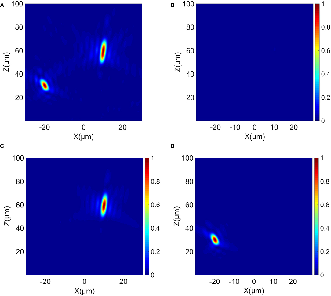
Figure 6. (A–D) Electric field intensity profile for different state of VO2, Designed focal position: . (A) For x-polarized incident light in the pass state. (B) For x-polarized incident light in the close state. (C) For LCP polarization incident in the B pass state. (D) For RCP polarized incidence in the (A) pass state.
Assigning the same focal point fA = fB = 50μm to the two regions A and B, so that under different incident polarized light, combining with temperature control, the intensity-adjustable polarization sensitive lens with same focal point can be obtained. When LP, RCP, LCP light is incident, adjusting the regional temperature so that the meta-lens is in the passing state, A passing state and B passing state. After the radius parameter is determined (here, r1 = 47.6μm, r2 = 84μm), the intensity of the focal point is different under the incidence of different polarized light, thus realizing a polarization-dependent lens, and its intensity can be controlled by the polarization state of the incident light.
The metalens has a numerical aperture NA = 0.859, which has a larger resolution. In the above three cases, different polarized light has the same focal point but different intensities, which realizes the intensity-adjustable polarization-dependent metasurface lens based on the P-B phase principle.
Figures 7A–C represent the focal spots on the y-z plane formed by X, LCP and RCP incident light after passing through the lens, and the focal spots on the x-y plane correspond to Figures 7D–F respectively. From the comparison in the figure, it can be seen that the focal lengths show good consistency in these three cases, and polarization-insensitive focusing under the conditions of X, RCP, and LCP is realized. Corresponding to X, RCP, LCP polarized light incident, the focusing efficiency is 38.33%, 42.94%, 35.38%, respectively. Figure 7G gives the normalized transmitted intensity under different polarized light incidence. The three intensities have certain differences, and the maximum intensity of x-polarized light is between the LCP and RCP intensities, realizing the focus of different incident light. This function can be applied in biomedical technology, through the polarization of incident light to control the intensity of the focal electric field after passing through the lens, which can adjust the resultant of all the external forces of cells, thereby achieving the function of capturing cells. In addition, we can also adjust the area size of the unit cell in the A and B areas to control the intensity ratio of the focus.
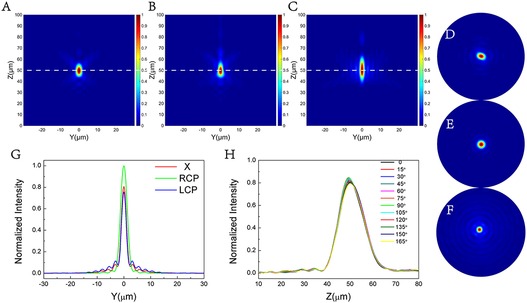
Figure 7. Electric field intensity profile (y–z plane) for (A) LP incident light, (B) RCP incident light, (C) LCP incident light. (D–F) The electric field intensity diagram of the x–y plane, corresponding to the diagrams (A–C). (G) The change of normalized electric field intensity with y in the three cases (z = 50 μm, x = 0), the FWHM is 2.31 μm, 2.71 μm, and 2.10 μm, respectively. (H) The normalized distribution of electric field intensity on the propagation plane (x = 0, y = 0) of linearly polarized light with different polarization angles.
We change the angle between the linearly polarized light and the x-axis to explore the effect of linearly polarized light with different deflection angles on the focus. Figure 7H shows the normalized distribution of electric field intensity on the propagation plane (x = 0, y = 0) of linearly polarized light with different polarization angles after passing through the metalens. It can be found that the position of the focal spot under different polarization angles is about 50 μm, and the intensity is basically the same. Therefore, we can conclude that the focus of linearly polarized light with different angles to the x-axis is basically the same after passing through the metalens.
The metalens designed in two regions: A and B, and there will be some optical losses in the two regions when different light sources incident, which is also the main cause of optical losses. There is a scheme in which the two types of structural elements can be interlaced. This arrangement can reduce optical loss to a certain extent. Our future work will also focus on this aspect.
In order to characterize the performance of the above designed metasurface lens, we simulated the change of the focal length when it deviated from the design wavelength, as shown in Figure 8A, where the focal change simulated here is consistent with the focal shift of the diffractive lens. The focal shift of the diffractive lens can be given by [46]:
Here, λ represents the wavelength of the incident light, λ0 represents the design wavelength, and f0 represents the design focal length. Figures 8B,C, respectively, show the normalized electric field distribution on the propagation plane and the horizontal focal plane when the incident wavelength is changed from 3.8 μm to 4.5 μm. We can intuitively see that as the incident wavelength increases within a certain range, the focal length gradually decreases, and when the incident wavelength is far from the design wavelength, the focal spot intensity gradually decreases. It can be seen from Figure 8D that the designed metasurface lens (symbol) is very consistent with the focal position of the diffractive lens (line) with the same geometric parameters.
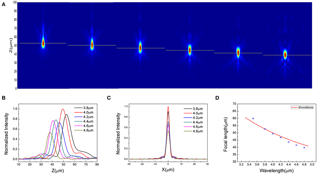
Figure 8. Chromatic aberration analysis under the incidence of x-polarized light ranging from 3.8 to 4.8 μm. (A) The normalized electric field intensity in the Y–Z plane. (B) and (C), respectively, represent the normalized electric field distribution of different incident wavelengths on the propagation plane and the horizontal focal plane. (D) The comparison between the focal position of the meta-lens designed in the mid-infrared band (symbol) and the focal point of the traditional diffractive lens (line) is simulated.
In conclusion, we design a multifunctional metalens based on vanadium dioxide material. By changing the state of the two areas of the temperature control lens, it is possible to switch among dual focus, single focus and no focus at any position, and the lens with the opposite helicity conversion and adjustable focus can be realized. The focusing efficiency in pass state, A pass state and B pass state are 31.53%, 32.45%, and 41.76%, respectively. At the same time, we verify that the focal point of the lens can be extended to any position within a certain area and has a good focusing effect. In addition, a polarization dependent lens is designed based on the same principle, and a polarization sensitive lens with adjustable intensity under LP, LCP, and RCP is realized by controlling the incident light of different polarization combining with temperature adjustment of the region. Finally, we investigate the aberration of the lens, which showed good consistency with the diffractive lens.
The raw data supporting the conclusions of this article will be made available by the authors, without undue reservation.
YS: conceptualization, software, data curation, writing–original draft preparation, and visualization. YS and WL: methodology. YS, XW, and FW: validation. FW, ZW, HM, and WL: formal analysis. YS and FW: investigation. FW, ZW, WL, XW, HM, HZ, and NL: writing—review and editing. FW: supervision and project administration. All authors contributed to the article and approved the submitted version.
This work is supported by National Natural Science Foundation of China (Grant No. 61774062 and No. 11674109), The Science and Technology Planning Project of Guangdong Province, China (Grant No. 2017A020219007), and Project of Department of Education of Guangdong Province, China (No.2019KTSCX257).
The authors declare that the research was conducted in the absence of any commercial or financial relationships that could be construed as a potential conflict of interest.
The reviewer QS declared a shared affiliation with one of the authors, XW, to the handling editor at time of review.
1. Wen D, Yue F, Li G, Zheng G, Chan K, Chen S, et al. Helicity multiplexed broadband metasurface holograms. Nat Commun. (2015) 6:8241. doi: 10.1038/ncomms9241
2. Zheng G, Muhlenbernd H, Kenney M, Li G, Zentgraf T, Zhang S. Metasurface holograms reaching 80% efficiency. Nat Nanotechnol. (2015) 10:308–12. doi: 10.1038/nnano.2015.2
3. Chen WT, Yang KY, Wang CM, Huang YW, Sun G, Chiang ID, et al. High-efficiency broadband meta-hologram with polarization-controlled dual images. Nano Lett. (2014) 14:225–30. doi: 10.1021/nl403811d
4. Jin L, Dong Z, Mei S, Yu YF, Wei Z, Pan Z, et al. Noninterleaved metasurface for (2(6)-1) spin- and wavelength-encoded holograms. Nano Lett. (2018) 18:8016–24. doi: 10.1021/acs.nanolett.8b04246
5. Grady N, Heyes J, Roy Chowdhury D, Zeng Y, Reiten M, Azad A, et al. Terahertz metamaterials for linear polarization conversion and anomalous refraction. Science (New York, NY). (2013) 340:1304–7. doi: 10.1126/science.1235399
6. Cong L, Xu N, Gu J, Singh R, Han J, Zhang W. Highly flexible broadband terahertz metamaterial quarter-wave plate. Laser Photon Rev. (2014) 8:626–32. doi: 10.1002/lpor.201300205
7. Zhang X, Yang S, Yue W, Xu Q, Tian C, Zhang X, et al. Direct polarization measurement using a multiplexed Pancharatnam–Berry metahologram. Optica. (2019) 6:1190–6. doi: 10.1364/OPTICA.6.001190
8. Yue F, Wen D, Zhang C, Gerardot BD, Wang W, Zhang S, et al. Multichannel polarization-controllable superpositions of orbital angular momentum states. Adv Mater. (2017) 29:1603838. doi: 10.1002/adma.201603838
9. Devlin RC, Ambrosio A, Rubin NA, Mueller JPB, Capasso F. Arbitrary spin-to–orbital angular momentum conversion of light. Science. (2017) 358:896–901. doi: 10.1126/science.aao5392
10. Almeida E, Shalem G, Prior Y. Subwavelength nonlinear phase control and anomalous phase matching in plasmonic metasurfaces. Nat Commun. (2016) 7:10367. doi: 10.1038/ncomms10367
11. Ye W, Zeuner F, Li X, Reineke B, He S, Qiu C-W, et al. Spin and wavelength multiplexed nonlinear metasurface holography. Nat Commun. (2016) 7:11930. doi: 10.1038/ncomms11930
12. Walter F, Li G, Meier C, Zhang S, Zentgraf T. Ultrathin nonlinear metasurface for optical image encoding. Nano Lett. (2017) 17:3171–5. doi: 10.1021/acs.nanolett.7b00676
13. Walther B, Helgert C, Rockstuhl C, Setzpfandt F, Eilenberger F, Kley EB, et al. Photonics: spatial and spectral light shaping with metamaterials (Adv. Mater. 47/2012). Adv Mater. (2012) 24:6251. doi: 10.1002/adma.201290300
14. Yin X, Ye Z, Rho J, Wang Y, Zhang X. Photonic spin hall effect at metasurfaces. Science. (2013) 339:1405. doi: 10.1126/science.1231758
15. Chen X, Chen M, Mehmood MQ, Wen D, Yue F, Qiu CW, et al. Longitudinal multifoci metalens for circularly polarized light. Adv Opt Mater. (2015) 3:1201–6. doi: 10.1002/adom.201500110
16. Khorasaninejad M, Chen W, Zhu A, Oh J, Devlin R, Rousso D, et al. Multispectral chiral imaging with a meta-lens. Nano Lett. (2016) 16:4595–600. doi: 10.1364/CLEO_AT.2016.JTh4A.5
17. Zhang F, Pu M, Luo J, Yu H, Luo X. Symmetry breaking of photonic spin-orbit interactions in metasurfaces. Opto Electron Eng. (2017) 44:319–25. doi: 10.3969/j.issn.1003-501X.2017.03.006
18. Ji R, Chen K, Ni Y, Hua Y, Long K, Zhuang S. Dual-focuses metalens for copolarized and cross-polarized transmission waves. Adv Condens Matter Phys. (2018) 2018:1–7. doi: 10.1155/2018/2312694
19. de Gracia P, Dorronsoro C, Marcos S. Multiple zone multifocal phase designs. Opt Lett. (2013) 38:3526–9. doi: 10.1364/OL.38.003526
20. Lin R, Li X. Multifocal metalens based on multilayer Pancharatnam–Berry phase elements architecture. Opt Lett. (2019) 44:2819. doi: 10.1364/OL.44.002819
21. Liu H, Lu J, Wang XR. Metamaterials based on the phase transition of VO2. Nanotechnology. (2017) 29:024002. doi: 10.1088/1361-6528/aa9cb1
22. Chu CH, Tseng ML, Chen J, Wu PC, Chen YH, Wang HC, et al. Active dielectric metasurface based on phase-change medium. Laser Photon Rev. (2016) 10:986–94. doi: 10.1002/lpor.201600106
23. Bai W, Yang P, Wang S, Huang J, Chen D, Zhang Z, et al. Tunable duplex metalens based on phase-change materials in communication range. Nanomaterials. (2019) 9:993. doi: 10.3390/nano9070993
24. Xu N, Liang Y, Hao Y, Mao M, Guo J, Liu H, et al. A thermal tuning Meta-Duplex-Lens (MDL): design and characterization. Nanomaterials (Basel). (2020) 10:1135. doi: 10.3390/nano10061135
25. Kim TT, Kim H, Kenney M, Park HS, Kim HD, Min B, et al. Amplitude modulation of anomalously refracted terahertz waves with gated-graphene metasurfaces. Adv Opt Mater. (2018) 6:1700507. doi: 10.1002/adom.201700507
26. Wen QY, Zhang HW, Yang QH, Xie YS, Chen K, Liu YL. Terahertz metamaterials with VO2 cut-wires for thermal tunability. Appl Phys Lett. (2010) 97:021111. doi: 10.1063/1.3463466
27. Barker AS, Verleur HW, Guggenheim HJ. Infrared optical properties of vanadium dioxide above and below the transition temperature. Phys Rev Lett. (1966) 17:1286–9. doi: 10.1103/PhysRevLett.17.1286
28. Long L, Taylor S, Wang L. Enhanced infrared emission by thermally switching the excitation of magnetic polariton with scalable microstructured VO2 metasurfaces. ACS Photon. (2020) 8: 2219–27. doi: 10.1021/acsphotonics.0c00760
29. Kort-Kamp WJM, Kramadhati S, Azad AK, Reiten MT, Dalvit DAR. Passive radiative “thermostat” enabled by phase-change photonic nanostructures. ACS Photon. (2018) 5:4554–60. doi: 10.1021/acsphotonics.8b01026
30. Ito K, Nishikawa K, Iizuka H, Toshiyoshi H. Experimental investigation of radiative thermal rectifier using vanadium dioxide. Appl Phys Lett. (2014) 105:253503. doi: 10.1063/1.4905132
31. Liu M, Xu Q, Chen X, Plum E, Li H, Zhang X, et al. Temperature-controlled asymmetric transmission of electromagnetic waves. Sci Rep. (2019) 9:4097. doi: 10.1038/s41598-019-40791-4
32. He J, Xie Z, Sun W, Wang X, Ji Y, Wang S, et al. Terahertz tunable metasurface lens based on vanadium dioxide phase transition. Plasmonics. (2016) 11:1285–90. doi: 10.1007/s11468-015-0173-2
33. Solyankin PM, Esaulkov MN, Chernykh IA, Kulikov IV, Zanaveskin ML, Kaul AR, et al. Terahertz switching focuser based on thin film vanadium dioxide zone plate. J Infrared Millimeter Terahertz Waves. (2018) 39:1203–10. doi: 10.1007/s10762-018-0540-0
34. Chen W, Chen R, Zhou Y, Ma Y. A switchable metasurface between meta-lens and absorber. IEEE Photon Technol Lett. (2019) 31:1187–90. doi: 10.1109/LPT.2019.2917439
35. Ding F, Zhong S, Bozhevolnyi SI. Vanadium dioxide integrated metasurfaces with switchable functionalities at terahertz frequencies. Adv Opt Mater. (2018) 6:1701204. doi: 10.1002/adom.201701204
36. Hashemi MRM, Yang SH, Wang T, Sepúlveda N, Jarrahi M. Electronically-controlled beam-steering through vanadium dioxide metasurfaces. Sci Rep. (2016) 6:35439. doi: 10.1038/srep35439
37. Chen W, Chen R, Zhou Y, Chen R, Ma Y. Spin-dependent switchable metasurfaces using phase change materials. Opt Express. (2019) 27:25678–87. doi: 10.1364/OE.27.025678
38. Butakov NA, Valmianski I, Lewi T, Urban C, Ren Z, Mikhailovsky AA, et al. Switchable plasmonic–dielectric resonators with metal–insulator transitions. ACS Photon. (2017) 5:371–7. doi: 10.1021/acsphotonics.7b00334
39. Mao M, Liang Y, Liang R, Zhao L, Xu N, Guo J, et al. Dynamically temperature-voltage controlled multifunctional device based on VO2 and graphene hybrid metamaterials: perfect absorber and highly efficient polarization converter. Nanomaterials. (2019) 9:1101. doi: 10.3390/nano9081101
40. Verleur HW, Barker AS, Berglund CN. Optical properties of VO2 between 0.25 and 5 eV. Phys Rev. (1968) 172:788–98. doi: 10.1103/PhysRev.172.788
41. Choi HS, Ahn JS, Jung J, Kim DH. Mid-infrared properties of a VO2 film near the metal-insulator transition. Phys Rev B Condens Matter. (1996) 54:4621–8. doi: 10.1103/PhysRevB.54.4621
42. Hasman E, Kleiner V, Biener G, Niv A. Polarization dependent focusing lens by use of quantized Pancharatnam–Berry phase diffractive optics. Appl Phys Lett. (2003) 82:328–30. doi: 10.1063/1.1539300
43. Aieta F, Genevet P, Kats MA, Yu N, Blanchard R, Gaburro Z, et al. Aberration-free ultrathin flat lenses and axicons at telecom wavelengths based on plasmonic metasurfaces. Nano Lett. (2012) 12:4932–6. doi: 10.1021/nl302516v
44. Berry MV. The adiabatic phase and pancharatnam's phase for polarized light. J Modern Opt. (1987) 34:1401–7. doi: 10.1080/09500348714551321
45. Bai W, Yang P, Wang S, Huang J, Chen D, Zhang Z, et al. Actively tunable metalens array based on patterned phase change materials. Appl Sci. (2019) 9:4927. doi: 10.3390/app9224927
Keywords: multifunctional metasurface, tunable meta-lens, phase transition material, multiple focus, polarization-sensitive
Citation: Song Y, Liu W, Wang X, Wang F, Wei Z, Meng H, Lin N and Zhang H (2021) Multifunctional Metasurface Lens With Tunable Focus Based on Phase Transition Material. Front. Phys. 9:651898. doi: 10.3389/fphy.2021.651898
Received: 11 January 2021; Accepted: 01 April 2021;
Published: 29 April 2021.
Edited by:
Fuli Zhang, Northwestern Polytechnical University, ChinaReviewed by:
Qian Sun, Nankai University, ChinaCopyright © 2021 Song, Liu, Wang, Wang, Wei, Meng, Lin and Zhang. This is an open-access article distributed under the terms of the Creative Commons Attribution License (CC BY). The use, distribution or reproduction in other forums is permitted, provided the original author(s) and the copyright owner(s) are credited and that the original publication in this journal is cited, in accordance with accepted academic practice. No use, distribution or reproduction is permitted which does not comply with these terms.
*Correspondence: Faqiang Wang, ZnF3YW5nQHNjbnUuZWR1LmNu
Disclaimer: All claims expressed in this article are solely those of the authors and do not necessarily represent those of their affiliated organizations, or those of the publisher, the editors and the reviewers. Any product that may be evaluated in this article or claim that may be made by its manufacturer is not guaranteed or endorsed by the publisher.
Research integrity at Frontiers
Learn more about the work of our research integrity team to safeguard the quality of each article we publish.