 Kazunori Takahashi
 Ryoji Imai
- Department of Electrical Engineering, Tohoku University, Sendai, Japan
A fast and automatically controlled frequency-tunable radiofrequency (rf) system is installed in an rf plasma thruster consisting of a stepped-diameter insulator source tube wound by a single-turn loop antenna and a solenoid providing a magnetic nozzle, and immersed in vacuum. The frequency and the output power are controlled so as to minimize the reflection coefficient and to maintain the net power corresponding to the forward minus reflected powers at a constant level. The reproducibility of the impedance matching and the stability of the net rf power are assessed, showing the fast impedance matching within about 10 msec and the long and stable delivery of the rf power to the thruster. When increasing the rf power up to 500 W, discontinuous changes in the source plasma density, the imparted thrust, and the signal intensity of the ion beam downstream of the thruster are observed, indicating effects of the discharge mode on the thruster performance and the ion energy distribution.
Introduction
Spontaneous accelerations of charged particles can be frequently observed in space, astrophysical, and laboratory plasmas [1, 2]. Especially, unmagnetized ions having a mass much heavier than the electrons are significantly affected by electric fields rather than magnetic fields; hence the potential structure plays an important role in the ion acceleration processes in weakly magnetized plasmas [3–5]. When a plasma density decays due to a volume expansion, an axial electric field accelerating the ions and confining the electrons develops in the plasmas. Charles and Boswell have discovered a formation of a current-free electric double layer, which has a potential drop over a narrow region of about a few tens of Debye length, in the magnetically expanding radiofrequency (rf) plasmas [6]. A number of subsequent experiments have also shown the similar structure or a broader (but still narrower than the scale of the magnetic field gradient) potential drop over about 10 cm in the expanding magnetic fields [7–16]. Measurements of ion energy distributions by using a retarding field energy analyzer and a laser-induced fluorescence method have shown a generation of a supersonic ion beam at the low-potential side, where the number of the beam ions decays along the axis due to a charge exchange process [7]. The magnetic field configuration and strength are key parameters in the spontaneous ion acceleration phenomenon as demonstrated before [17, 18], where the ion beam is generated when the Larmor radius of the ions becomes smaller than the source radius [19].
Measurement of an electron energy probability function (eepf) in the magnetically expanding rf plasma has identified the presence of the two species of electrons: trapped and free electrons, where the high energy (but low temperature population) electrons overcome the potential drop and neutralize the accelerated ion beam [20]. Since the energy source of the potential drop is considered to be the electron energy as discussed in [21], the electron energy distribution significantly affects the ion acceleration energy. Actually, the increases in both the ion beam energy and the electron temperature with a decrease in the operating gas pressure have been detected so far [16, 22, 23].
Thrusts imparted by magnetic nozzle rf plasma thrusters have been assessed for the last decade by using thrust balances [24–29], where the thrust is the reaction force of the momentum exhausted from the system per unit time. The above-mentioned electrostatic ion acceleration does not increase the thrust due to the absences of both any external energy source and the vector conversion of the momentum [30]. However, the generation of the collimated ion beam would be beneficial for the thruster since the accelerated ions can be detached from the magnetic field lines [31–35], where the electron detachment from the magnetic nozzle is still an open question [36–41]. The direct measurement of the force exerted to the magnetic field has demonstrated a thrust enhancement by the magnetic nozzle, where a Lorentz force arising from an azimuthal electron diamagnetic current and a radial magnetic field is exerted to the magnetic field, being equivalent to an electron pressure force to the expanding magnetic field [30, 42–44]. Various configurations of the thruster have been tested so far and the thruster efficiency has been gradually increased and approaches twenty percent in recent years [45]. Furthermore, a new application of the magnetic nozzle rf plasma thruster to contactless space debris removal has been proposed and the proof of the principle has been demonstrated in a laboratory experiment [46].
To mount the thruster on a spacecraft, development of peripheral components being compact, light, and robust, is also important issue. In early stage of fundamental studies, permanent magnet configurations, which lead eliminations of heavy solenoids and dc power supplies, have been designed to form the magnetic nozzles. Chen has demonstrated the efficient plasma production with annular permanent magnets [47]. One of authors and Virko et al. [10] have demonstrated the spontaneous ion acceleration in the expanding magnetic fields formed by the permanent magnets [9, 10]. The rf system including a generator and a matching box often dominates the weight and volume of the thruster, in addition to the solenoids and the dc power supplies. Since the load impedance is significantly affected by plasma parameters (e.g., the plasma density and the electron temperature), the impedance tuning is an important element of the rf plasma thruster operation, especially with undefined composition of the propellant for an air-breathing electric propulsion and the use of propellants created from in situ resource utilization [48, 49]. The load impedance is typically adjusted by changing the variable capacitors in the matching circuit. This type of the matching circuit requires a mechanical motion control preventing the matching circuit from being compact. Furthermore, the time lag of the communication between the spacecraft and the ground control station would be a serious problem for the impedance matching; it would be desirable to include the automatic controller for the impedance tuning. To overcome the issue on the matching box, several types of the rf generators have adjusted the frequency to match the load impedance to the output impedance of the generator [50–53], where fixed capacitors are used in the matching circuit. A recently developed fast and automatically controlled rf system has demonstrated the fast impedance matching for the rf plasma source [54], where the source tube is attached to a vacuum flange of a chamber and the rf antenna wound around the source tube is exposed to the atmosphere. On the other hand, the whole structure of the plasma source including the antenna has to be immersed in vacuum for the thruster assessment configuration.
Here the fast and automatically controlled rf system operational in the frequency range of 37–43 MHz and with the maximum power of about 500 W is installed in the helicon plasma thruster immersed in vacuum, where the thruster is attached to a pendulum thrust balance. The impedance tuning can be typically accomplished within several msec and the net power (corresponding to the forward minus reflected powers) is maintained at a constant level during the discharge, providing the stable steady-state operation of the thruster. The imparted thrust and the ion energy distribution function are measured by using a thrust balance and a retarding field energy analyzer (RFEA), respectively, showing the thrust of a few mN for 500 W rf power and the spontaneous generation of the supersonic ion beam. Discontinuous increases in the thrust, the source plasma density, and the ion beam component, are clearly observed when increasing the rf power. The ion beam component enhanced simultaneously with the discharge mode transition implies that the presence of the high-density plasma at the high-potential side is useful to the increase in the ion beam current. The energy of the supersonic ion beam and the electron temperature increase with a decrease in the gas flow rate. The results are consistent with the previous experiments using 13.56 MHz rf generators [2, 45].
Experimental Setup
Figure 1A shows the schematic diagram of the experimental setup, together with the calculated magnetic field lines. A helicon thruster consists of a stepped-diameter (65–95 mm inner diameter and 70–100 mm outer diameter) pyrex glass source tube wound by a single-turn water-cooled rf loop antenna and a solenoid providing a static magnetic field expanding downstream of the source, i.e., the magnetic nozzle. The detailed structure of the thruster design can be found in Ref. [55] and the rf antenna is covered with insulators and further covered with a grounded metallic structure to suppress parasitic discharges outside the source tube [56]. The thruster is attached to a pendulum thrust balance installed inside a 1-m-diameter and 2-m-long cylindrical vacuum chamber, which is evacuated by three turbomolecular pumping [labeled as “TMP” in Figure 1A] systems to a base pressure lower than 10−4 Pa. It is noted that the rf loop antenna is mechanically isolated from the source tube to ensure the pendulum motion of the thrust balance. The upstream side of the source is terminated by an insulator plate having a small gas injection port. Argon gas is continuously introduced from the gas injection port into the source tube via a mass flow controller located outside the chamber. For typical gas flow rate of CAr = 70 ± 1 sccm, the argon gas pressure measured at the chamber side wall is about 25 ± 1 mPa. It should be mentioned that the thrust measurement for different pumping speeds, i.e., different gas pressures for the constant gas flow rate, has been performed previously, showing the unchanged thrust, where the measurement has been performed at 25 and 75 mPa [57]. This implies that the thruster performance is not affected by the gas ingestion. The performance assessment at the lower gas pressure cannot be performed due to the limit of the vacuum facility. A dc current IB is supplied to the solenoid to form the magnetic nozzle, where the calculated magnetic field strength on the z axis is plotted in Figure 1B, showing that the magnetic field has a throat of about 650 G at the larger-diameter region of the source tube (z ~ −3.5 cm). The rf antenna is powered from the rf generator (briefly described later) via an impedance matching circuit, resulting in a plasma production in the source tube, where the capacitances in the matching circuit are unchanged to demonstrate the automatic and fast control of the frequency tuning.
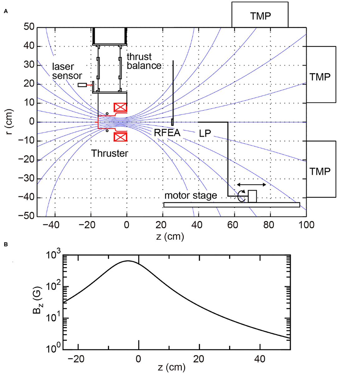
Figure 1. (A) Schematic diagram of the experimental setup together with the calculated magnetic field lines (blue solid lines). (B) Calculated magnetic field strength on the z axis.
The rf generator is very similar to that used in the previous experiment [53], while the maximum output power can be increased up to about 500 W in the present setup. Briefly, it consists of a voltage-controlled oscillator (VCO), a voltage-variable attenuator (VVA), a main amplifier, a bi-directional coupler, and power detectors, as shown in Figure 2. A board controller (National Instruments, sbRIO-9637) is mounted on the system, which consists of a field-programmable gate array (FPGA) and analog-digital/digital-analog convertors. The board has digital-input (DI), digital-output (DO), analog-input (AI), and analog-output (AO) channels. The frequency and the power of the rf signal inputted to the main amplifier can be controlled by the AO signals to the VCO and the VVA, respectively. The amplified rf power is transferred to a load (including the capacitors and the plasma source) via the bi-directional coupler. The rf signals corresponding to the forward and reflected powers are converted into dc voltages by using coaxial schottky barrier diode detectors and the low pass filters (LPF), which are measured by the AI channels. A gate signal is inputted into the DI channels; the same signal outputted from the DO channel is inputted into the main amplifier to turn on the rf power. During the detection of a high logic level by the DI channel, the frequency and the power are controlled by the board so as to minimize the reflection coefficient and to maintain the net rf power at a constant level, where the reflection coefficient and the net power are calculated on the board from the measured forward (Pf) and reflected (Pr) powers as
respectively. It should be noted that the power delivered to the load is not the forward power Pf but the net power Pnet. The detected signals of the forward and reflected powers are calibrated by using an rf wattmeter with an accuracy of 5%, resulting in errors of about 7.5% in Gr (for typical powers of Pf = 500 W and Pr = 20 W) and about 5% in Pnet. Typical dc-rf conversion efficiency in the main amplifier is about 74%. To assess the overall efficiency of the source, estimation of the rf power delivered to the plasma, i.e., the rf power transfer efficiency to the plasma, is required. This has not been performed yet and remains a further experimental issue.
As shown in Figure 1A, the whole structure of the thruster is attached to a plate suspended by flexible thin metallic plates from a top plate of the thrust balance, where the length of the arms is about 24 cm. The displacement induced by the plasma production is measured by a commercial laser displacement sensor with a resolution of 0.1 mm. The absolute value of the thrust can be obtained by multiplying a calibration coefficient to the measured displacement, where the calibration coefficient is obtained by measuring the displacement vs. known force before pumping down the chamber and is confirmed to be unchanged after venting the chamber. The validity of the thrust measurement technique has been shown in the previous experiment with the comparison between the thrust balance and the target techniques [58].
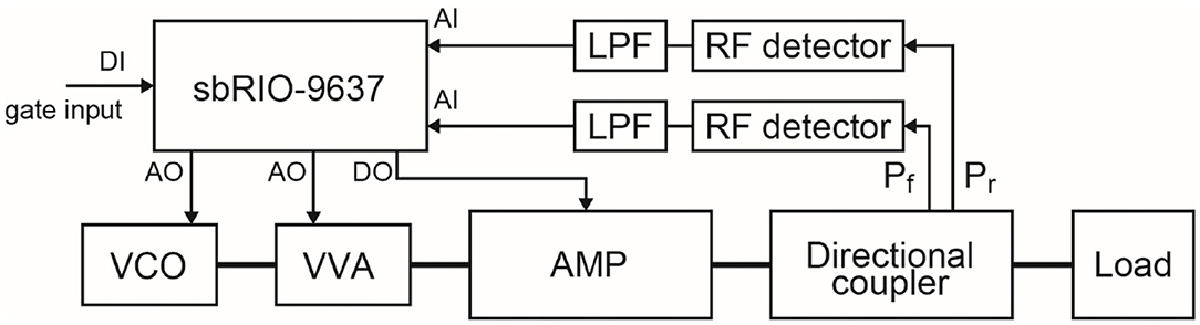
Figure 2. Schematic circuit diagram of the rf system.
The plasma density, the electron temperature, and the ion energy distribution function (IEDF) are measured by a radially facing 3-mm-diameter planar Langmuir probe mounted on a movable motor stage and an RFEA located at z = 25 cm. The plasma density np can be obtained from an ion saturation current Iis as
where e, uB, and S are the elementary charge, the Bohm velocity, and the surface area of the probe tip, respectively, and a measured electron temperature is used for the calculation of the Bohm velocity, e.g., Te ~ 4.5 ± 0.5 eV for the gas flow rate of 70 sccm. As the detector faces in the radial direction, the estimated density corresponds to that of the thermal ions. The RFEA consists of a collector electrode and two meshes: the first mesh contacting the plasma is electrically floating and the second one is used as a repeller for the electrons. The IEDF is known to be proportional to the first derivative of the collector voltage (Vc)-current (Ic) characteristic, which is obtained by a pulsed Langmuir probe technique [59].
Results
Figure 3 shows the typical temporal evolutions of (A) the gate signal and the rf frequency (f ), (B) the forward (Pf) and reflected (Pr) powers, and (C) the net power (Pnet) and the square of the reflection coefficient (), where the initial value of the frequency, the pulse width of the rf power, and the target value of the net power are set at ~39.1 MHz, 100 msec, and 500 W, respectively. It is found that the rf frequency automatically changes from ~39.1 to ~38.7 MHz within the initial 7 msec; the value of is significantly reduced from unity to 0.03, corresponding to the power reflection of about 3%, at t ~ 7 msec. The net power Pnet is also found to approach the target value of 500 W during the pulse.
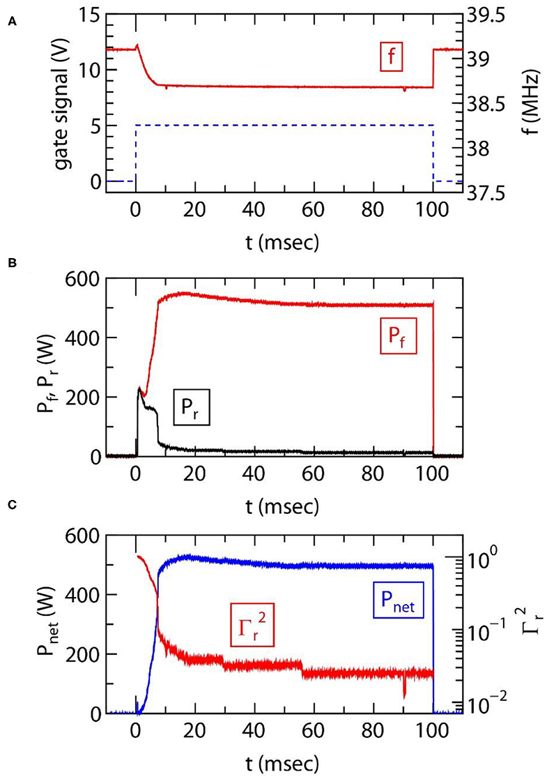
Figure 3. Temporal evolutions of (A) the rf gate signal (a dashed line), the frequency f of the rf power (a red solid line), (B) the forward power Pf (a red solid line), the reflected power Pr (a black solid line), (C) the net rf power Pnet (a blue solid line), and the square of the reflection coefficient (a red sold line), where the pulse width of the rf power, the initial value of the frequency, and the target value of the net power, are set at 100 msec, 39.1 MHz, and 500 W, respectively.
By taking data of 1,000 shots, the statistical analyses for the tuning time (ttune), the rf powers (Pf, Pr, Pnet), and the square of the reflection coefficient () are performed, where ttune is defined as the time spent for reducing the value of to 0.1. A probability density function (PDF) of ttune presented in Figure 4A shows the typical tuning time of about 7.5 ± 0.5 msec and the reproducibility can be confirmed from this PDF even in the thruster immersed in vacuum, as well as the previous experiment using the rf antenna exposed to atmosphere [60]. The PDFs of the rf powers and presented in Figures 4B,C, respectively, are calculated from the data for t > 50 msec to discuss the power controllability in the steady state, implying the sharp peaks in the PDFs of the rf powers as seen in Figure 4B. The PDF of in Figure 4C shows the reproduced impedance matching giving the power reflection of about 3%. Therefore, the fast and automatically controlled rf system can be utilized in the thruster development, where the plasma source structure including the rf antenna is immersed in vacuum.
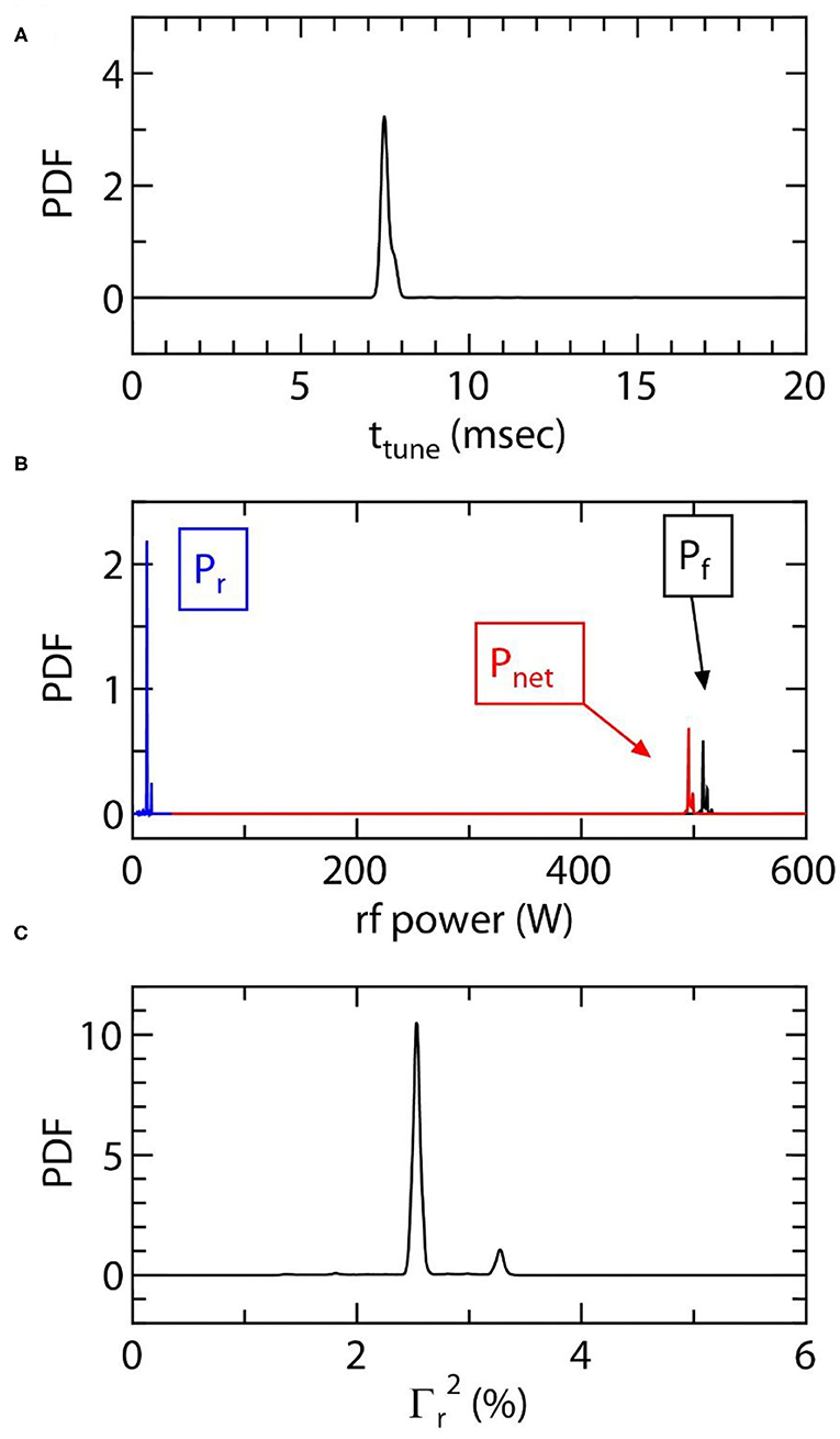
Figure 4. Probability density functions (PDFs) of (A) the tuning time ttune, (B) the forward power Pf (a black solid line), the reflected power Pr (a blue solid line), the net power Pnet (a red solid line), and (C) the square of the reflection coefficient . These are obtained from the data taken by 1,000 shots repetition.
Steady state operation of the thruster is also an important issue. Figure 5 shows the measured Pnet and f for the long pulse of 180 sec, where the target value of Pnet is set at 450 W. It is found that the frequency is immediately changed from the initial 39.1 to ~38.65 MHz and slightly changed during the pulse. The slight change in the frequency seems to be due to the change in the wall temperature of the source tube, where the temperature of the water-cooled antenna is expected to be unchanged. It can be seen that Pnet is maintained at 450 W during the discharge pulse of 180 s, indicating the stable operation of the rf system.
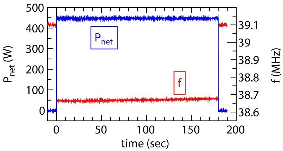
Figure 5. Temporal evolutions of the net power Pnet (a blue solid line) and the rf frequency f (a red solid line), where the pulse width and the target value of the net power are set at 180 s and 450 W, respectively.
Measurement of the thrust as a function of Pnet is performed for the gas flow rate of 70 sccm and the result is plotted by filled squares in Figure 6. The thrust is found to increase with an increase in the rf power and a slight discontinuous change can be seen at Pnet ~ 350 W. Open circles in Figure 6 show the plasma density np measured by the Langmuir probe located at z = −10 cm and the discontinuous jump of the density can be observed at the similar power of Pnet ~ 350 W, which is considered to be due to the discharge mode transition from capacitively- to inductively-coupled discharges. The maximum thrust obtained in the present experiment is about 3.5 mN for the rf power of 500 W, which seems to be similar to that obtained with 13.56 MHz rf generator [55].
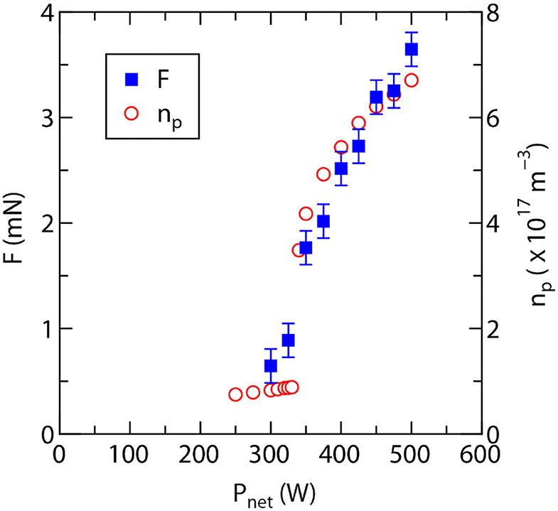
Figure 6. Thrust F measured by the thrust balance and plasma density np taken at z = −10 cm as functions of the net power Pnet.
Figure 7a shows the typical IEDF (blue solid line) taken at z = 25 cm for the gas flow rate of CAr = 70 sccm and the net power of Pnet = 500 W, clearly showing the two peaks corresponding to the low-energy thermal ions at ~38 V (plasma potential) and the high-energy beam ions at ~51 V (beam potential). The measured data can be well-fitted by a superimposition of two Gaussians (dashed lines) as drawn by a red solid line. Figure 7b shows the normalized IEDFs as a function of Pnet, where the fitting curves are used to draw the contour plot. At the net rf power of Pnet ~ 350 W, the peak of the ion beam is found to be enhanced simultaneously with the discharge mode transition observed in Figure 6. Therefore, it is demonstrated that the discharge mode inside the source significantly affects the ion energy distribution function downstream of the source tube; the presence of the high-density plasma in the source tube can yield the increase in the ions accelerated from the high- to low-potential sides.
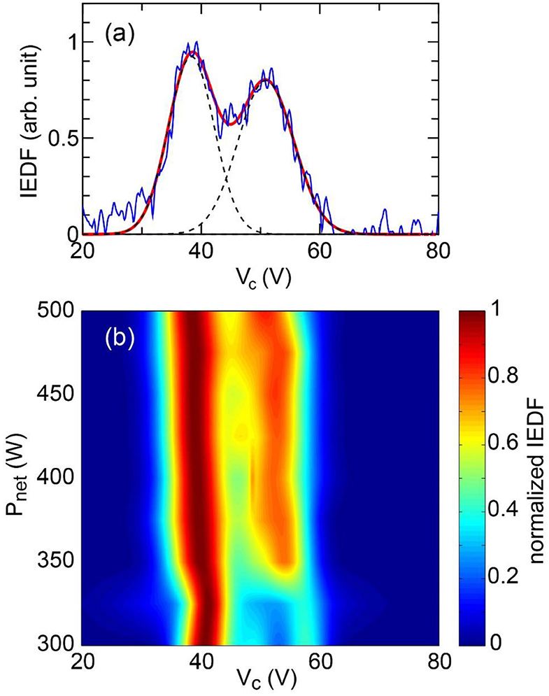
Figure 7. (a) IEDF (a blue solid line) taken at z = 25 cm together with the Gaussian fitting curve (a red solid line) given by the sum of the two Gaussians drawn by dashed lines, where the gas flow rate and the net rf power are chosen as 70 sccm and 500 W, respectively. (b) Contour plot of the normalized IEDF as a function of the net rf power Pnet, where the Gaussian fitting curves are used to draw the contour plot.
Figure 8A shows the axial profile of the plasma density np for the same conditions as Figure 7a and the axial decay of the density is enhanced near the thruster exit (z = 0–10 cm). When assuming a uniform electron temperature, the voltage V from the reference position (density of np0) can be given by the Boltzmann relation as
and the calculated V from the data in Figure 8A is plotted in Figure 8B. It is noted that the difference between the plasma and beam potentials in the IEDF taken at z = 25 cm is about 12.5 V as seen in Figure 7a. A red dashed line in Figure 8B indicates the axial position giving the 12.5-V-higher potential than that at z = 25 cm. This result implies that the accelerated ion beam comes from the high potential side near the thruster exit. The velocity of the 12.5 eV ions is about 7.7 km/sec, while the ion sound speed corresponding to the Bohm velocity for Te = 4.5 eV is about 3.3 km/sec. Therefore, the ion Mach number can be estimated as ~2.3 and the detected ion beam is found to be supersonic. It should be mentioned that the IEDFs in the present experiment (Figure 7) seem to be broadened, compared with that observed in the previous experiment showing the formation of the current-free double layer, which has a nearly discontinuous potential drop [61]. Possible reasons of the broadened IEDF are a poor energy resolution of the RFEA and the spatially broadened potential drop near the thruster exit over about 10 cm scale as in Figure 8.
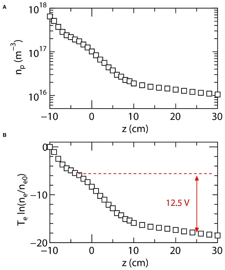
Figure 8. (A) Axial profile of the measured plasma density np on the z axis for Pnet = 500 W and CAr = 70 sccm. (B) Voltage V from the reference position (z = −10 cm) calculated from the Boltzmann relation assuming a uniform electron temperature, where the measured temperature of Te = 4.5 eV is used for the calculation. The dashed line and the arrow indicate the potential difference corresponding to the beam energy of εbeam ~ 12.5 eV [seen in Figure 7a], implying that the beam ions are accelerated from the source tube.
Both the ion beam energy and the electron temperature have been observed to increase with a decrease in the operating gas pressure (or the gas flow rate) [22, 23]. This change in the ion beam energy can be interpreted as a result of the flux balance between the accelerated ions and the electrons overcoming the potential drop, as discussed in Ref. [20, 21, 45]. Figure 9 shows the measured plasma potential Vp, the beam potential Vbeam, the beam energy εbeam = Vbeam – Vp, and the electron temperature Te, as functions of the gas flow rate CAr. The present results also show the similar trends to the previous observations [22, 23] and the detected beam energy is about 3–3.5 times as large as the electron temperature over the pressure range tested here. This value is different from the potential drop estimation satisfying the flux balance between the ions and electrons for the Maxwellian electron energy distribution, i.e., ~5.2Te. This discrepancy seems to be due to the assumption of the Maxwellian electron energy distribution, since the previously measured energy distribution has a depleted tail and close to the Druyvesteyn rather than the Maxwellian [23]. Therefore, the detailed measurement of the electron energy distribution is required to verify the flux balance between the electrons and ions. The characteristics of the ion beam and the imparted thrust similar to the previous experiments show that the fast- and automatically-controlled rf power system does not impact the thruster performance, while it would be important technique to operate the thruster for the undefined composition of the propellant, e.g., the air-breathing electric propulsion. When the imparted thrust is expected to be changed by the propellant composition even if the impedance matching is well-performed, the rf output power has to be controlled to maintain the constant thrust level, which remains further development issue.
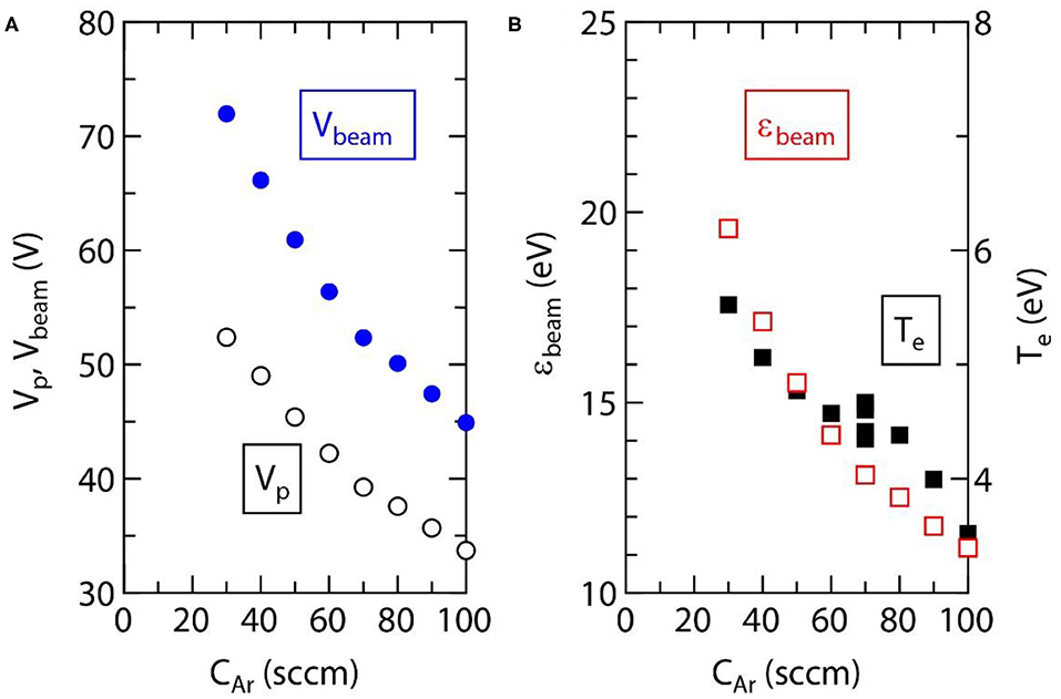
Figure 9. (A) Plasma potential Vp (open circles) and beam potential Vbeam (filled circles) as functions of the gas flow rate CAr, where these potentials are obtained from the Gaussian fitting curves (not shown here) of the measured IEDF at z = 25 cm. (B) Calculated ion beam energy εbeam (open squares) from the data in (A) and electron temperature Te (filled squares) taken at z = 10 cm as functions of CAr.
Since the rf generator includes the similar components, such as the oscillator, the amplifier, and the power sensors, the weight and size of the rf generator would be similar to the traditional rf system. However, the use of only the fixed capacitors in the matching circuit would reduce the size and weight of the matching circuit, as the traditional system includes the large size variable capacitors and the mechanical motors. Typical weight and size of the commercial and traditional rf system for semiconductor process seem to be 5–10 kg and 10 × 20 × 30 cm3 for the matching circuit (including the variable capacitors and the mechanical controllers), and about 10 kg and 15 × 45 × 25 cm3 for the rf generator. It is expected that the matching circuit can be contained in about 5 × 5 × 5 cm3 in size and <1 kg in weight for the frequency-tunable rf system. Therefore, the present system will roughly reduce the size and weight in half for the 500-W-class rf system.
Conclusion
The fast and automatically controlled frequency-tunable rf system is attached to the magnetic nozzle rf plasma thruster immersed in vacuum, where the rf frequency can be adjusted in the range of 37–43 MHz and the maximum output power can be increased up to about 500 W. The frequency and the output power are automatically controlled, yielding the minimized reflection coefficient and the net power maintained at a constant level with the good reproducibility and the stable steady-state operation. The maximum thrust of 3.5 mN is obtained for the rf power of ~500 W, where the increase in the thrust can be observed simultaneously with the discharge mode transition. The presence of the supersonic ion beam is shown by the measurement of the ion energy distribution, where the enhancement of the ion beam component is detected simultaneously with the discharge mode transition. This implies that the high-density plasma production at the high-potential side is the key element of the ion beam generation. The present results show that the fast- and automatically-controlled rf system does not impact the thruster performance, being useful to reduce the size and the weight of the rf system.
Data Availability Statement
The original contributions presented in the study are included in the article/Supplementary Material, further inquiries can be directed to the corresponding author.
Author Contributions
KT designed the concepts of the experiment, the setup, and the frequency-tunable rf system. The setup was performed by KT, RI, and KH. The data were taken by all authors and analyzed by KT. The results were discussed by all authors. The manuscript written by KT was reviewed by RI and KH.
Funding
This work is partially supported by a grant-in-aid for scientific research (18K18746 and 19H00663) from the Japan Society for the Promotion of Science, A-step program by Japan Science and Technology Agency, and Casio Science Promotion Foundation.
Conflict of Interest
The authors declare that the research was conducted in the absence of any commercial or financial relationships that could be construed as a potential conflict of interest.
References
1. Meier DL, Koide S, Uchida Y. Magnetohydrodynamic production of relativistic jets. Science. (2001) 291:84. doi: 10.1126/science.291.5501.84
2. Charles C. A review of recent laboratory double layer experiments. Plasma Sources Sci Technol. (2007) 16:R1. doi: 10.1088/0963-0252/16/4/R01
3. Charles C, Boswell RW, Hawkins R. Oblique double layers: a comparison between terrestrial and auroral measurements. Phys Rev Lett. (2009) 103:095001. doi: 10.1103/PhysRevLett.103.095001
4. Takahashi K, Igarashi Y, Fujiwara T. Plane and hemispherical potential structures in magnetically expanding plasmas. Appl Phys Lett. (2010) 97:041501. doi: 10.1063/1.3467857
5. Williams LT, Walker MLR. Plume structure and ion acceleration of a helicon plasma source. IEEE Trans Plasma Sci. (2015) 43:1694. doi: 10.1109/TPS.2015.2419211
6. Charles C, Boswell RW. Current-free double-layer formation in a high-density helicon discharge. Appl Phys Lett. (2003) 82:1356. doi: 10.1063/1.1557319
7. Sun X, Keesee AM, Biloiu C, Scime EE, Meige A, Charles C, et al. Observation of ion-beam formation in a current-free double layer. Phys Rev Lett. (2005) 95:025004. doi: 10.1103/PhysRevLett.95.025004
8. Plihon N, Chabert P, Corr CS. Experimental investigation of double layers in expanding plasmas. Phys Plasmas. (2007) 14:013506. doi: 10.1063/1.2424429
9. Takahashi K, Oguni K, Yamada H, Fujiwara T. Ion acceleration in a solenoid-free plasma expanded by permanent magnets. Phys Plasmas. (2008) 15:084501. doi: 10.1063/1.2965497
10. Virko VF, Virko YV, Slobodyan VM, Shamrai KP. The effect of magnetic configuration on ion acceleration from a compact helicon source with permanent magnets. Plasma Sources Sci Technol. (2010) 19:015004. doi: 10.1088/0963-0252/19/1/015004
11. Fredriksen Å, Mishra LN, Byhring HS. The effects of downstream magnetic field on current-free double layers and beam formation in the Njord helicon plasma device. Plasma Sources Sci Technol. (2010) 19:034009. doi: 10.1088/0963-0252/19/3/034009
12. Wiebold M, Sung Y-T, Scharer E. Experimental observation of ion beams in the Madison helicon experiment. Phys Plasmas. (2011) 18:063501. doi: 10.1063/1.3596537
13. Longmier BW, Bering EA III, Carter MD, Cassady LD, Chancery WJ, Chang Díaz FR, et al. Ambipolar ion acceleration in an expanding magnetic nozzle. Plasma Sources Sci Technol. (2011) 20:015007. doi: 10.1088/0963-0252/20/1/015007
14. Cannat F, Lafleur T, Jarrige J, Chabert P, Elias P-Q, Packan D. Optimization of a coaxial electron cyclotron resonance plasma thruster with an analytical model. Phys Plasmas. (2015) 22:053503. doi: 10.1063/1.4920966
15. Little J, Choueiri EY. Electron cooling in a magnetically expanding plasma. Phys Rev Lett. (2016) 117:225003. doi: 10.1103/PhysRevLett.117.225003
16. Zhang X, Aguirre E, Thompson DS, McKee J, Henriquez M, Scime EE. Pressure dependence of an ion beam accelerating structure in an expanding helicon plasma. Phys Plasmas. (2018) 25:023503. doi: 10.1063/1.5018583
17. Charles C, Boswell RW. The magnetic-field-induced transition from an expanding plasma to a double-layer containing expanding plasma. Appl Phys Lett. (2007) 91:201505. doi: 10.1063/1.2814877
18. Takahashi K, Shida Y, Fujiwara T. Magnetic-field-induced enhancement of ion beam energy in a magnetically expanding plasma using permanent magnets. Plasma Sources Sci Technol. (2010) 19:025004. doi: 10.1088/0963-0252/19/2/025004
19. Takahashi K, Charles C, Boswell RW, Fujiwara T. Double-layer ion acceleration triggered by ion magnetization in expanding radiofrequency plasma sources. Appl Phys Lett. (2010) 97:141503. doi: 10.1063/1.3499653
20. Takahashi K, Charles C, Boswell RW, Kaneko T, Hatakeyama R. Measurement of the energy distribution of trapped and free electrons in a current-free double layer. Phys Plasmas. (2007) 14:114503. doi: 10.1063/1.2803763
21. Chen FF. Physical mechanism of current-free double layers. Phys Plasmas. (2006) 13:034502. doi: 10.1063/1.2179393
22. Lieberman MA, Charles C. Theory for formation of a low-pressure, current-free double layer. Phys Rev Lett. (2006) 97:045003. doi: 10.1103/PhysRevLett.97.045003
23. Takahashi K, Charles C, Boswell RW, Fujiwara T. Electron energy distribution of a current-free double layer: druyvesteyn theory and experiments. Phys Rev Lett. (2011) 107:035002. doi: 10.1103/PhysRevLett.107.035002
24. Takahashi K, Lafleur T, Charles C, Alexander P, Boswell RW, Perren M, et al. Direct thrust measurement of a permanent magnet helicon double layer thruster. Appl Phys Lett. (2011) 98:141503. doi: 10.1063/1.3577608
25. Pottinger S, Lappas V, Charles C, Boswell R. Performance characterization of a helicon double layer thruster using direct thrust measurements. J Phys D Appl Phys. (2011) 44:235201. doi: 10.1088/0022-3727/44/23/235201
26. Shabshelowitz A, Gallimore AD. Performance and probe measurements of a radio-frequency plasma thruster. J Propul Power. (2013) 29:919. doi: 10.2514/1.B34720
27. Williams LT, Walker MLR. Thrust measurements of a radio frequency plasma source. J Propul Power. (2013) 29:520. doi: 10.2514/1.B34574
28. Takahashi K, Komuro A, Ando A. Effect of source diameter on helicon plasma thruster performance and its high power operation. Plasma Sources Sci Technol. (2015) 24:055004. doi: 10.1088/0963-0252/24/5/055004
29. Vialis T, Jarrige J, Aanesland A, Packan D. Direct thrust measurement of an electron cyclotron resonance plasma thruster. J Propul Power. (2018) 34:1323. doi: 10.2514/1.B37036
30. Fruchtman A. Electric field in a double layer and the imparted momentum. Phys Rev Lett. (2006) 96:065002. doi: 10.1103/PhysRevLett.96.065002
31. Gesto FN, Blackwell BD, Charles C, Boswell RW. Ion detachment in the helicon double-layer thruster exhaust beam. J Propul Power. (2006) 22:24. doi: 10.2514/1.13914
32. Cox W, Charles C, Boswell RW, Hawkins R. Spatial retarding field energy analyzer measurements downstream of a helicon double layer plasma. Appl Phys Lett. (2008) 93:071505. doi: 10.1063/1.2965866
33. Takahashi K, Fujiwara T. Observation of weakly and strongly diverging ion beams in a magnetically expanding plasma. Appl Phys Lett. (2009) 94:061502. doi: 10.1063/1.3080205
34. Terasaka K, Yoshimura S, Ogiwara K, Aramaki M, Tanaka MY. Experimental studies on ion acceleration and stream line detachment in a diverging magnetic field. Phys Plasmas. (2009) 17:072106. doi: 10.1063/1.3457139
35. Takahashi K, Itoh Y, Fujiwara T. Operation of a permanent-magnets-expanding plasma source connected to a large-volume diffusion chamber. J Phys D Appl Phys. (2011) 44:015204. doi: 10.1088/0022-3727/44/1/015204
36. Hooper EB. Plasma detachment from a magnetic nozzle. J Propul Power. (1993) 9:757. doi: 10.2514/3.23686
37. Arefiev AV, Breizman BN. Magnetohydrodynamic scenario of plasma detachment in a magnetic nozzle. Phys Plasmas. (2005) 12:043504. doi: 10.1063/1.1875632
38. Deline CA, Bengtson RD, Breizman BN, Tushentsov MR, Jones JE, Chavers DG, et al. Plasma detachment from a magnetic nozzle. Phys Plasmas. (2009) 16:033502. doi: 10.1063/1.3080206
39. Ahedo E, Merino M. On plasma detachment in propulsive magnetic nozzles. Phys Plasmas. (2011) 18:053504. doi: 10.1063/1.3589268
40. Takahashi K, Ando A. Laboratory observation of a plasma-flow-state transition from diverging to stretching a magnetic nozzle. Phys Rev Lett. (2017) 118:225002. doi: 10.1103/PhysRevLett.118.225002
41. Little JM, Choueiri EY. Electron demagnetization in a magnetically expanding plasma. Phys Rev Lett. (2019) 123:145001. doi: 10.1103/PhysRevLett.123.145001
42. Ahedo E, Merino M. Two-dimensional supersonic plasma acceleration in a magnetic nozzle. Phys Plasmas. (2010) 17:073501. doi: 10.1063/1.3442736
43. Takahashi K, Lafleur T, Charles C, Alexander P, Boswell RW. Electron diamagnetic effect on axial force in an expanding plasma: experiments and theory. Phys Rev Lett. (2011) 107:235001. doi: 10.1103/PhysRevLett.107.235001
44. Takahashi K, Charles C, Boswell RW. Approaching the theoretical limit of diamagnetic-induced momentum in a rapidly diverging magnetic nozzle. Phys Rev Lett. (2013) 110:195003. doi: 10.1103/PhysRevLett.110.195003
45. Takahashi K. Helicon-type radiofrequency plasma thrusters and magnetic plasma nozzles. Rev Mod Plasma Phys. (2019) 3:3. doi: 10.1007/s41614-019-0024-2
46. Takahashi K, Charles C, Boswell RW, Ando A. Demonstrating a new technology for space debris removal using a bi-directional plasma thruster. Sci Rep. (2018) 8:14417. doi: 10.1038/s41598-018-32697-4
47. Chen FF, Torreblanca H. Large-area helicon source with permanent magnets. Plasma Phys Control Fusion. (2006) 49:A81. doi: 10.1088/0741-3335/49/5A/S07
48. Schonherr T Komurasaki K Romano F Massuti-Ballester B Herdrich G Analysis of atmosphere-breathing electric propulsion. IEEE Trans Plasma Sci. (2015) 43:287. doi: 10.1109/TPS.2014.2364053
49. Ishimatsu T Weck OL Hoffman JA Ohkami Y Shishko R Generalized multicommodity network flow model for the Earth-Moon-Mars logistics system. J. Spacecr Rockets. (2016) 53:25. doi: 10.2514/1.A33235
50. Ziemba T, Euripides P, Slough J, Winglee R, Giersch L, Carscadden J, et al. Plasma characteristics of a high power helicon discharge. Plasma Sources Sci Technol. (2006) 15:517. doi: 10.1088/0963-0252/15/3/030
51. Charles C, Boswell RW, Bish A. Variable frequency matching to a radiofrequency source immersed in vacuum. J Phys D Appl Phys. (2013) 46:365203. doi: 10.1088/0022-3727/46/36/365203
52. Takahashi K, Nakano Y, Ando A. Frequency-tuning radiofrequency plasma source operated in inductively-coupled mode under a low magnetic field. J Phys D Appl Phys. (2017) 50:265201. doi: 10.1088/1361-6463/aa7524
53. Charles C, Liang W, Raymond L, Rivas-Davila J, Boswell RW. Vacuum testing a miniaturized switch mode amplifier powering an electrothermal plasma micro-thruster. Front Phys. (2017) 5:36. doi: 10.3389/fphy.2017.00036
54. Takahashi K, Hanaoka K, Ando A. Fast and automatic control of a frequency-tuned radiofrequency plasma source. Front Phys. (2020) 7:227. doi: 10.3389/fphy.2019.00227
55. Takahashi K, Takao Y, Ando A. Thrust imparted by a stepped-diameter magnetic nozzle rf plasma thruster. Appl Phys Lett. (2018) 113:034101. doi: 10.1063/1.5041034
56. Takahashi K. Radiofrequency antenna for suppression of parasitic discharges in a helicon plasma thruster experiment. Rev Sci. Instrum. (2012) 83:083508. doi: 10.1063/1.4748271
57. Takahashi K Takao Y And A. Low-magnetic-field enhancement of thrust imparted by a stepped-diameter and downstream-gas-injected rf plasma thruster. Plasma Sources Sci Technol. (2019) 28:085014. doi: 10.1088/1361-6595/ab3100
58. Takahashi K, Komuro A, Ando A. Measurement of plasma momentum exerted on target by a small helicon plasma thruster and comparison with direct thrust measurement. Rev Sci Instrum. (2015) 86:023505. doi: 10.1063/1.4907797
59. Takahashi K, Charles C, Boswell R, Lieberman MA, Hatakeyama R. Characterization of the temperature of free electrons diffusing from a magnetically expanding current-free double layer plasma. J Phys D Appl Phys. (2010) 43:162001. doi: 10.1088/0022-3727/43/16/162001
60. Hanaoka K, Takahashi K, Ando A. Reproducibility of a plasma production in a fast- and automatically-controlled radio frequency plasma source. IEEE Trans Plasma Sci. (2020) 48:2138. doi: 10.1109/TPS.2020.2987554
Keywords: rf plasma thruster, impedance matching, rf generator, thrust, ion beam
Citation: Takahashi K, Imai R and Hanaoka K (2021) Automatically Controlled Frequency-Tunable rf Plasma Thruster: Ion Beam and Thrust Measurements. Front. Phys. 9:639010. doi: 10.3389/fphy.2021.639010
Received: 08 December 2020; Accepted: 08 March 2021;
Published: 31 March 2021.
Edited by:
Roderick William Boswell, Australian National University, AustraliaReviewed by:
Mitchell L. R. Walker, Georgia Institute of Technology, United StatesWonho Choe, Korea Advanced Institute of Science and Technology, South Korea
Amelia Greig, The University of Texas at El Paso, United States
Copyright © 2021 Takahashi, Imai and Hanaoka. This is an open-access article distributed under the terms of the Creative Commons Attribution License (CC BY). The use, distribution or reproduction in other forums is permitted, provided the original author(s) and the copyright owner(s) are credited and that the original publication in this journal is cited, in accordance with accepted academic practice. No use, distribution or reproduction is permitted which does not comply with these terms.
*Correspondence: Kazunori Takahashi, a2F6dW5vcmlAZWNlaS50b2hva3UuYWMuanA=