
95% of researchers rate our articles as excellent or good
Learn more about the work of our research integrity team to safeguard the quality of each article we publish.
Find out more
BRIEF RESEARCH REPORT article
Front. Phys. , 15 March 2021
Sec. Optics and Photonics
Volume 9 - 2021 | https://doi.org/10.3389/fphy.2021.636696
This article is part of the Research Topic Optics and Photonics in Space View all 7 articles
 Yoshihiko Saito*
 Hideki TakenakaKoichi ShiratamaYasushi MunemasaAlberto Carrasco-Casado
 Phuc V. TrinhKenji SuzukiTetsuharu FuseYasuhiro TakahashiToshihiro Kubo-oka
 Morio Toyoshima
In recent years, the necessity of free-space optical (FSO) communications has increased as a method for realizing high-speed communications between satellites and the ground. However, one disadvantage of FSO communications is the significant influence of the atmosphere. Specifically, FSO communications cannot be utilized under certain atmospheric conditions, especially in the presence of clouds. One of the solutions to this problem is the site diversity technique, which makes it possible to select a given ground station with better atmospheric conditions among a number of fixed ground stations. The other solution is to prepare a ground station that can be moved to a place with better atmospheric conditions. We applied the latter method and developed a transportable optical ground station in NICT. We utilize a realistic telescope diameter, which is about 30 cm at the maximum, capable of being set up quickly, and with a pointing accuracy of about 100 µrad. In addition, it is necessary to prepare a fine-pointing optical system that performs tracking with about 1/10 of the pointing accuracy of the telescope. In this paper, we report the results of the first performance test of the transportable optical ground station in NICT.
In order to accelerate the communication speed between satellites and ground stations, free-space optical (FSO) communications will be a key technique and the demand for FSO communication has greatly increased in the last few years [1]. However, FSO communications between space and ground is affected by the atmosphere, such as cloud blockages and atmospheric turbulence. One possible solution to mitigate the effect of cloud blockages is site diversity; however, a large number of fixed ground stations are usually required to be implemented. In addition, in case of emergency, FSO communications at an arbitrary location would be required, since fixed ground stations cannot respond to this situation. Thus, we proceed to develop a transportable optical ground station (TOGS), which can be moved to a place with better atmospheric conditions or a location requiring a communication site with space and able to deploy the functionality of an optical station. Development of TOGS was made by the Institute of Communications and Navigation of the German Erospace Center (DLR) [2, 3]. and by NICT with a compact 2 × 2 × 4 m3 ground station being transportable with a truck and capable of 40 Gbit/s lasercom with an aircraft [4]. NICT started the development of another TOGS in 2018 [5, 6]. In this paper, we introduce the research and development of this TOGS. We show the concept and the specifications of TOGS in Concept of Transportable Optical Ground Station and Specifications of Transportable Optical Ground Station respectively. Although the fine-pointing system is included in components of TOGS, it is not a fundamental component and still in manufacturing. Therefore, we report the results of the first performance test of the coarse pointing system as a fundamental performance of TOGS in Results of the Performance Test. We discuss the conclusion of this research and development in Conclusion.
The basic concept of a TOGS is that it works as an optical ground station in any place. The main requirement is to be transportable by a vehicle that can travel on public roads in order to move from a standby place to a site where a communication link is required. The deployed location of the TOGS is assumed to be in any place, and the setup of the TOGS should be completed as soon as possible at that location. To achieve this requirement, the telescope is preferably integrated with the transportation vehicle, and in order to handle the changing weather conditions, it is necessary to store the telescope and other instruments immediately in case of rain. To be able to establish stable communication links with aircrafts or satellites, we have to suppress the telescope vibrations. We show an image of the vehicle and mounted components the telescope in Figure 1. Based on this concept, we organize the requirements for the TOGS.
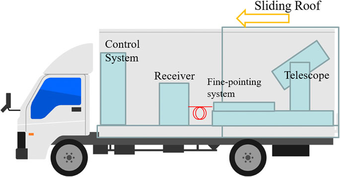
FIGURE 1. An image of the vehicle and mounted components.
The basic requirement is that the vehicle as well as the enclosure of the TOGS can travel on a public road and can be operated by a regular truck driver’s license in Japan. This is also a restriction in order to design the system. It is necessary to provide a vibration-absorbing function on the vehicle while moving so that the communication instruments are not affected. This function must work while moving on off-roads because the deployment location might be far from public roads. In order to deploy the ground station as soon as possible, we have to promptly complete the setup of the telescope for pointing to the aircraft or satellite. Therefore, the telescope must be integrated within the vehicle, and the vehicle must have a function to open its roof in order to receive the optical beam from the aircraft or satellite. The field of view of the telescope needs to have an arbitrary angle of elevation beyond the horizon with respect to all azimuthal directions. We require that the telescope installed in the vehicle has the largest possible aperture.
For the stability of optical communications, the vehicle must have a mechanism to mitigate vibrations. It is necessary to provide a mechanism to obtain the location information of the ground station deployment, and calculate the relationship between the direction of the telescope and the position on the celestial sphere for the setup of the TOGS. We require an optical system that efficiently transmits the photons collected by the telescope to the receiver, and an interface with an external power supply because an internal power supply would generate vibrations. It is also necessary to provide an interface to an external communication network.
We divided the elements of this development into three components: the vehicle, the telescope, and the fine-pointing optics. The vehicle and its additional parts provide the base of a system that transports a communication device without instruments failure and can be quickly deployed at any destination. The telescope must be able to efficiently collect the photons propagating in space and to provide a pointing accuracy sufficient to acquire a light source into the field of view of the telescope. Since the pointing accuracy of the telescope is not enough to stabilize the communication, we must install the fine-pointing optics that enables to stabilize the signal intensity which is inputted to the receiver. We performed the design of the vehicle and the telescope in 2018. The manufacture of the vehicle was completed in the early of 2019. The manufacture of telescope was completed in the end of 2019, and it was integrated on the vehicle in the early of 2020.
The specifications of the vehicle are shown in Table 1. An eight-ton truck is a realistic assumption for the maximum size allowable to travel on public roads with a regular license in Japan. Air suspension during the transportation is required, such as a vibration-absorbing mechanism. A hydraulic jack mechanism is also equipped to fix the vehicle to the ground at a deployed place as an additional equipment for the vehicle. The pedestal on which the telescope is installed was equipped with a vibration-isolation mechanism on the floor of the vehicle. The optical bench for the fine-pointing system was also mounted on this vibration-isolation system, because this optics must be fixed to the telescope. The vehicle has a retractable roof above the telescope. While only the directions of yaw, pitch and minus roll will be available for communications, we can arrange the vehicle toward any arbitrary orientation. Therefore, we will be able to adjust the direction of the vehicle in accordance to the orbit of the spacecraft. As external interfaces, the vehicle is also equipped with power supply connectors and network connectors. In order to avoid vibration and to save the load weight, the power supply was decided to be supplied externally. Therefore, the TOGS requires the support from a power supply vehicle or a power supply infrastructure at the deployment destination. The network is also equipped with an RJ45 connector for connecting an Ethernet cable. Information such as temperature control at the vehicle base of NICT can be acquired remotely through this cable. In addition, the space for installing the receiver and its control instruments is also secured, as well as the space for the maintenance.
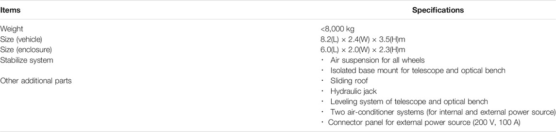
TABLE 1. Specifications of the vehicle.
The specifications of the telescope are as shown in Table 2. The diameter of the telescope is 35.5 cm, considering the vehicle size and load bearing capacity. We adopted an azimuth mount for the telescope in order to fix the vehicle in any arbitrarily orientation. Since the optical bench for the fine-pointing optics is fixed to the vehicle, the beam for communications is required to be transmitted from the coudé path to the optical bench. In order to secure the pointing accuracy of the telescope, we will first acquire the position information of the ground station, and then perform a pointing analysis by using stars to improve the accuracy of the orientation. We show the result of the performance test in the next section. The control system of the telescope is installed on the rack mounted PC. This PC is also mounted on the vehicle. If some operators are on the vehicle, it causes the vibrations that affect the tracking performance. Therefore, we can also control the telescope from the outside of the vehicle. We show the telescope integrated in the vehicle in Figure 2.
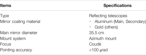
TABLE 2. Specifications of the telescope.
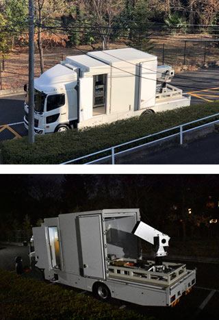
FIGURE 2. The telescope integrated in the vehicle.
The fine-pointing system should stabilize the intensity of light supplied from the telescope to the receiver. The design of this optical system is shown in Figure 3. The fine-pointing system consists of a sensor for measuring the positional deviation and a mirror for correcting the deviation. The goal of fine-pointing system should be achievement of the pointing accuracy of 4 μrad for coupling to single-mode fiber. The measurement of positional deviations is performed by a sensor dividing the wavefront into four parts. The mirror that controls the tip-tilt is operated to correct the positional shift. As mentioned above, the optical bench on which the fine-pointing optics is constructed is fixed to the vehicle. Therefore, these optics should be implemented to prevent any misalignment of the optics caused by vibrations while moving.
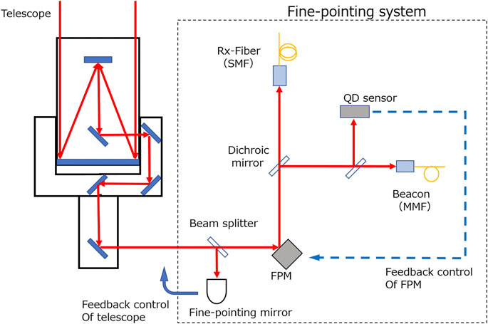
FIGURE 3. Fine-pointing optics of the TOGS.
We completed the design of the fine-pointing system in 2020 and will start manufacture this system in this year.
After the manufacture of the TOGS was completed in January 2020, the first performance evaluation of coarse pointing system of the telescope was started in February 2020. First, pointing performance evaluation was performed using TPOINT, which is a general-purpose software used for pointing a telescope. As a result of performing pointing using 20 bright stars, we obtained a pointing accuracy of 38.4 μrad rms. Since the field of view of the coarse tracking system using infrared camera put on the focal point of the Coudé path of the telescope was 1mrad, this pointing accuracy should be enough for pointing a flying object with coordinates on the celestial sphere. The required time for the pointing analysis is about 30 min.
We performed a test for pointing and tracking a satellite based on the orbit element prediction by Consolidated Prediction Format (CPF). The date of this test was February 21, 2020. We chose AJISAI satellite that is Experimental Geodetic Satellite for tracking test. We could capture AJISAI satellite at the same time as pointing of the satellite. We acquired images of AJISAI satellite as a point source by the camera attached on the Nasmyth focal point for 3 min and 15 s. The deviation of the center of the point source from the center position of the image is shown in Figure 4. We obtained the peak-to-peak tracking accuracy of 71.2 μrad under the condition of the wind speed at 5 m/s. We plan to install a closed-loop tracking system in this year. This closed-loop system will compensate the deviation of tracking in about 1 Hz. Therefore, we could compensate the long frequency deviation of tracking shown in Figure 4. More specifically, we obtained the accuracy of 30 μrad by applying this system. This closed-loop tracking system could allow the low pointing accuracy. Thus, the required number of stars for the pointing analysis should be smaller than 20, and the required time for this analysis should be shorter than 30 min. We also could secure the coarse accuracy of pointing by recalculating the pointing parameters based on the accurate parameters derived at any place, using the direction of telescope that is mounted on the horizontal base and acquisition of the location on the Earth. If this method is effective, the pointing analysis will not be required at all deployed places. In the future, we have to confirm the effectiveness of this method. Under strong wind conditions, the vibration of the vehicle should be severe. As a result, it is necessary to confirm how much the tracking accuracy is stabilized under this situation. We also performed an evaluation of the beam performance at the Coudé position. The collimated beam diameter is 20.13 mm. This value is given as one of the interface conditions for the fine-pointing system.
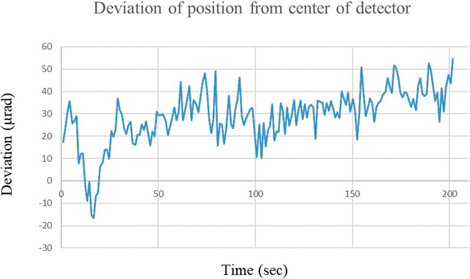
FIGURE 4. The deviation of tracking.
We have been designing and manufacturing the TOGS for 2 years. We have been developing it under the concept that is discussed in Concept of Transportable Optical Ground Station, in which the TOGS can be deployed at any place, and the telescope is mounted on the vehicle. In the development, we referred to the structure of the mobile astronomical telescope. Based on this structure, we designed the vehicle and determined the specifications of the telescopes that could be mounted on it. Since the load capacity of the vehicle is limited, it is necessary to adjust the weight of the equipment loading on the vehicle. In addition, the amount of electric power to be supplied was determined in consideration of the electric power required for the installed telescope and equipment. In order to ensure the vibration resistance required for our purpose, we applied the structures against the vibration during travel and the vibration when base stations are deployed. The former is a vibration-free floor for telescope and optical bench, and the latter is a mechanism to fix the vehicle by a hydraulic jack. Based on these requirements, we completed the design in 2018 and manufactured the TOGS in 2019. In order to verify the effect of the vibration-free floor, it is necessary to monitor the vibration by driving the vehicle on public road. We also plan to carry out vibration measurements during operations in this fiscal year. In the first performance test, since we performed only the coarse tracking test, we did not measure the vibrations faster than 1 Hz. It is also necessary to investigate the tracking accuracy in the high frequency and to measure and evaluate the fast vibration of the vehicle itself at the same time. The detailed design of the fine-pointing system is finished, and the manufacturing process will be started in this fiscal year. Since the fine-pointing system should be designed depending on the interface conditions with the receiver system, it is necessary to change the optical system depending on the receiver. We aimed to design for allowing the flexibility of implementation as much as possible.
The raw data presented in this article are not available in generally because it is confidential. Requests to access the datasets should be directed to author.
YS: Conceptualization, Investigation, Writing. HT: Investigation. KS: Investigation, Validation. YM: Validation. AC-C: Validation. PT: Validation, Writing. KS: Validation. TF: Conceptualization, Validation, Supervision. YT: Validation, Supervision. TK-o: Supervision. MT: Project administration.
This work is a part of “Research and Development of the Quantum Cryptography Technology for Satellite Communications (JPJ007462)” in “Research and Development of Information and Communications Technology (JPMI00316)” of Ministry of Internal Affairs and Communication (MIC), Japan and this work is supported by MIC.
The authors declare that the research was conducted in the absence of any commercial or financial relationships that could be construed as a potential conflict of interest.
1. Toyoshima M, Recent trends in space laser communications for small satellites and constellations. Proc. of International Conference on Space Optical Systems and Applications. Portland, OR: ICSOS (2019). doi:10.1109/ICSOS45490.2019.8978972
2. Shrestha A, Brechtelsbauer M. Transportable optical ground station for high-speed free-space laser communication. Proc SPIE (2012) 8517:851706. doi:10.1117/12.928966
3. Fischer E, Berkefeld T, Feriencik M, Feriencik M, Kaltenbach V, Soltau D, et al. “Development, integration and test of a transportable Adaptive optical ground station”. New Orleans, Louisiana, U.S .ICSOS 2012. (2015). doi:10.1109/ICSOS.2015.7425071
4. Toyoshima M, Munemasa Y, Takenaka H, Takayama Y, Koyama Y, Kunimori H, et al. Terrestrial free-space optical communications network testbed: innova. Proc. of International Conference on Space Optical Systems and Applications. Kobe, Japan: ICSOS (2014). doi:10.1109/JLT.2020.3009505
5. Saito Y, Munemasa Y, Takenaka H, Kunimori H, Kolev D, Alberto C-C, et al. Research and development of a transportable optical ground station in NICT. Proc. of International Conference on Space Optics; Chania, Greece. ICSO (2018). doi:10.1117/12.2536127
Keywords: free-space optical communication, ground station, stellites, transportable, fine-pointing system
Citation: Saito Y, Takenaka H, Shiratama K, Munemasa Y, Carrasco-Casado A, Trinh PV, Suzuki K, Fuse T, Takahashi Y, Kubo-oka T and Toyoshima M (2021) Research and Development of a Transportable Optical Ground Station in NICT: The Results of the First Performance Test. Front. Phys. 9:636696. doi: 10.3389/fphy.2021.636696
Received: 01 December 2020; Accepted: 02 February 2021;
Published: 15 March 2021.
Edited by:
Leontios Stampoulidis, Leo Space Photonics R&D, GreeceReviewed by:
Jianming Wen, Kennesaw State University, United StatesCopyright © 2021 Saito, Takenaka, Shiratama, Munemasa, Carrasco-Casado, Trinh, Suzuki, Fuse, Takahashi, Kubo-oka and Toyoshima. This is an open-access article distributed under the terms of the Creative Commons Attribution License (CC BY). The use, distribution or reproduction in other forums is permitted, provided the original author(s) and the copyright owner(s) are credited and that the original publication in this journal is cited, in accordance with accepted academic practice. No use, distribution or reproduction is permitted which does not comply with these terms.
*Correspondence: Yoshihiko Saito, c2FpdG95c0BuaWN0LmdvLmpw
Disclaimer: All claims expressed in this article are solely those of the authors and do not necessarily represent those of their affiliated organizations, or those of the publisher, the editors and the reviewers. Any product that may be evaluated in this article or claim that may be made by its manufacturer is not guaranteed or endorsed by the publisher.
Research integrity at Frontiers
Learn more about the work of our research integrity team to safeguard the quality of each article we publish.