- 1Medical Engineering and Technology Research Center, Shandong First Medical University, Shandong Academy of Medical Sciences, Taian, China
- 2Department of Radiation Oncology, University of Washington, Seattle, WA, United States
- 3Department of Biomedical Imaging & Radiological Sciences, National Yang-Ming University, Taipei, China
- 4Department of Radiation Oncology, Mayo Clinic Arizona, Phoenix, AZ, United States
Purpose: To develop a method for constructing customizable, multimodal quality control (QC) imaging phantoms based on 3D printing technology.
Materials and Methods: Four phantoms were designed and constructed through 3D printing technology using three unique printing materials. Physical parameters of the 3D printed materials were evaluated, including density, shore hardness, porosity, deformation temperature, computed tomography (CT) number, absorption coefficient, and printing accuracy. Imaging performance of the phantoms was studied using MRI, CT, PET/MR, and PET/CT, and compared with conventional/commercial phantoms. Imaging assessments included high contrast resolution, low contrast resolution, uniformity, deformation, SNR, slice accuracy/slice thickness, location accuracy/laser alignment, CT number, relaxation time, and registration.
Results: All three printing materials have a shore hardness of 90. The physical densities of these materials are 1.15 g/cm3, 0.76 g/cm3, and 1.27 g/cm3, respectively. The porosities are 9.09, 6.81, and 18.56%, respectively. The threshold temperature of deformation for the three materials is >105°C, which is higher than that of PMMA and silica gel. Imaging scans of the constructed phantoms for single modality scanners (MRI and CT) and dual-modality scanners (PET/MRI and PET/CT) were compared with those of the commercial phantoms. The standard deviation of the HU value uniformity test was <3 HU for CT scans.
Conclusion: 3D printed medical imaging phantoms allow for rapid, customized phantom fabrication for clinical situations across single and dual modality imaging platforms. Further imaging parameter analysis is underway to provide more quantitative evaluation of the proposed phantoms.
Introduction
Medical imaging quality assurance (QA) and quality control (QC) is facilitated by well-designed physical phantoms [1–4]. Most imaging phantoms are designed for a single imaging modality, such as those accredited by the American College of Radiology (ACR) and American Association of Physicists in Medicine (AAPM) specifically for computed tomography (CT), positron emission tomography (PET), or magnetic resonance imaging (MRI) [5, 6]. Standard phantoms are conventionally manufactured through molding or machine manufacturing [7]. While common commercial production methods, such as engraving holes in poly methyl methacrylate (PMMA) cylinders for CT phantom spatial resolution testing, are suitable for mass production, this approach offers limited flexibility for phantom customization for multimodal imaging QA/QC applications.
The decreasing cost of 3D printing technologies and material development has resulted in the ability to fabricate custom-designed, 3D printed multi-modality imaging phantom as a viable alternative. Commonly used 3D printing technologies include fused deposition modeling (FDM), stereo lithography appearance (SLA), and three-dimensional printing and gluing (3DP). A combination of materials can be used simultaneously for constructing a customized object using 3D modeling software. Such applications have been extensively explored for medical devices in the health industry thanks to the ease of rapid device prototyping and broad geometric printing flexibility [8–10]. For example, 3D printing technology has also been used for constructing phantoms for simulating human/animal anatomies [11–14], image quality evaluation and assurance [4, 15–19], radiation dose measurement, and other applications [20–26].
Standard imaging phantoms are compatible with a single imaging modality. The development of hybrid imaging such as MRI, CT, PET/CT, and PET/MR resulted in increasing demand for QA phantoms that are compatible with multiple imaging modalities to reduce cost and enhance ease of use [5, 6, 14, 19]. There are relatively few studies addressing multi-modality imaging QA phantoms using 3D printing [15, 16, 19]. Bieniosek et al. designed and printed a PET/MR phantom with improved spatial accuracy and reduced processing cost compared with commercial alternatives [15, 16]. However, this phantom had limited applicability due to its simple structure and limited testing parameters. Previous work from our group introduced 3D printed mouse models and a breast phantom compatible with CT, MRI, or ultrasound imaging QA [13, 27].
Based on our previous experience in fabricating and 3D printing multi-modality phantoms, the present study aims to (1) develop 3D-printed QA phantoms with custom-designed modules for single modality scanners (CT and MRI) and/or dual modality scanner (PET/MR and PET/CT) imaging evaluation capacities; and (2) evaluate imaging quality based on spatial resolution, contrast, geometric deformation, and uniformity. The overall goal is to explore cost-effective and customizable solutions for fabricating multi-modality imaging phantoms using 3D printing technology.
Materials and Methods
3D Printers and Phantom Materials
Three 3D printers were used in this study, including FDM (Objet Uprint Se, Stratasys, USA), SLA (Pangu, 4.0, Meditool, China), and Polyjet (Objet Connex 350, Stratasys, USA) printers. FDM 3D printing is accomplished through layer-by-layer deposition using a nozzle that moves in an x–y direction while extruding melted materials, i.e., Acrylonitrile butadiene styrene (ABS) or Polylactic Acid (PLA). SLA prints 3D objects layer-by-layer using a laser to activate a liquid photosensitive resin. Polyjet prints 3D objects layer-by-layer using a nozzle to extrude a photosensitive polymer material, which is then activated to polymerize using an ultraviolet lamp. Three printing materials were used for phantom construction. ABS P430 (Stratasys, USA) was used for phantom substrate and the external shell. SLA resins, Verowhite (Stratasys, USA), and MDT-white (Meditool, China) were used for phantom cylindrical inserts, i.e., CT number inserts, resolution inserts, etc.
Physical Characteristics of Phantom Materials
3D printed phantoms' physical stability, radiographic tissue equivalence, and geometry accuracy were evaluated for three materials (ABS, Verowhite, and MDT-white). An assessment of these materials' physical characteristics included density, shore hardness, porosity, photon absorption coefficient, CT number, and deformation temperature. The corresponding parameters of PMMA and silica gel were also measured and compared as reference, as they are conventional materials used for commercial phantoms.
Porosity was tested using a 0.5T desktop nuclear magnetic resonance (NMR) analyzer (PQ001-025V, Niumag analytical instrument corporation, China) and Carr-Purcell-Meiboom-Gill (CPMG) pulse sequencer. The test sample was 1.0 cm3 in size and was soaked in water for 24 h prior to testing. T2 values of the materials were compared between immersion and desiccation.
The porosity measurement method references the measurement of water penetrance in rocks [28, 29].
in which V is the pore volume, A is the surface area, T2B is the relaxation time of the surrounding water, and ρ2 is the surface relaxivity, which are dependent on the relaxation rate A. Water relaxation is negligible compared to the surface relaxation (), thus T2 reflects the average for a pore,
Consequently, T2 of the standard cutoff value is larger than the water in a drained pore. Thus, the compared ratio Porosity can be used to express the porosity of the materials, as described in Equation (3):
Shore hardness was measured with a hardness tester (Shore D Durometer, WHS-D, Wolpert, China). The thermal deformation temperature was determined when the material sample was heated with a Vicat Softening Temperature (VST) tester, which is a commonly used instrument for testing softening point temperature of plastic [30]. The test process is shown in Figure 1.

Figure 1. The test process of the material samples. (a) Placing material cubes (pointed by the red arrow) in the NMR for porosity test; (b,c) locking the samples (pointed by the red arrow) in the VST tester for deformation temperature assessment.
Material photon absorption coefficients were measured using a Digital Radiography (DR) (CXDI-55G, Canon, Japan) and ion chamber (PTW31033, PTW, Germany) at 70 and 120 kV. Material CT numbers were measured using a CT scanner (Brilliance-ICT, Philips, Netherlands) with 120 kV and 260 mA. The geometric accuracy of 3D printing was validated by measuring the slab thickness of a single layer printed with MDT-white, ABS P340, and Verowhite materials using the screw micrometer (Links, HMCT Group, China).
Phantom Structure Design
The phantom structure was designed using AutoCAD (AutoCAD 14, Autodesk, USA) and 3D Builder (3D Builder, Microsoft, USA), based on the QC guidelines from AAPM, ACR, and the National Electrical Manufactures Association (NEMA) for CT, MRI, and PET, respectively [31–34]. A novel modular insert design was used so that imaging QA components can be selected and customized based on the QC tests indicated for the different imaging modalities (CT, MRI, and PET), as shown in Figure 2a. The maximum number of phantom imaging layers is dictated by the dimensions of the internal cylinder shell. Phantoms can also be engineered such that the outer cylindrical shell is transparent, such as shown in Figure 2b, where the shell was made through conventional subtractive manufacturing with PMMA material. Inserts were optimized for stability and easy indexing/assembly by adding peripheral support posts. Figure 2c shows an example of a digital design of a phantom internal insert used for MRI modulation transfer function (MTF) test. Figure 3 shows the phantom schematic design, the module layers, and the size of the module/phantom can be customized as desired.
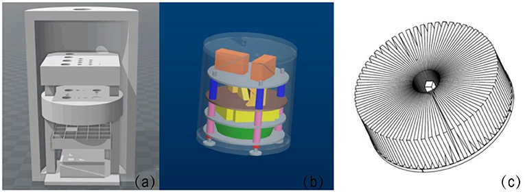
Figure 2. (a) Shows a schematic of the phantom model. (b) Shows a phantom design with internal layers and inserts in a transparent shell (PMMA). The peripheral support posts can be seen along the periphery of the phantom (blue, pink, and red components). (c) Shows a schematic of a star-shaped phantom internal layer designed for modulation transfer function (MTF) evaluation for MRI.
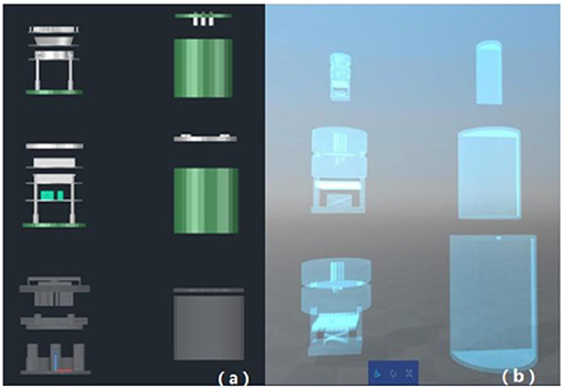
Figure 3. Phantom schematic design. (a) Shows the optional combination of 3D-printed test inserts and conventional PMMA shells; (b) shows the optional combination of entirely printed test inserts and shells.
Phantom Insert Design
Preliminary phantom assessment was performed by testing high contrast resolution, low contrast resolution, uniformity, deformation, signal-to-noise ratio (SNR), slice accuracy/slice thickness, location accuracy/laser alignment, CT number, relaxation time, and registration across various imaging platforms. Specific imaging modules were designed to test the above parameters, such as MTF star module (Figure 4A), layer thickness module (Figure 4B), line-pair high contrast resolution (Figure 4C) and low contrast resolution modules (Figure 4D), geometric distortion module (Figure 4E), and location accuracy/laser alignment module (Figure 4F).
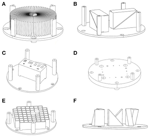
Figure 4. Three-dimensional design of a phantom module. (A) Star module, (B) layer thickness module, (C) line-pair high contrast resolution module, (D) low contrast resolution modules, (E) geometric distortion module, (F) location accuracy module.
The contrast resolution inserts were designed with a testing range of 1–11 line-pairs (LP)/cm for MRI and a high contrast resolution (hotspot) test with a range of 1–8 LP/cm for PET. The inserts used for CT had a testing range of 1–21 LP/cm, using high-density silica gel for line-pairs. The testing range is customizable depending on phantom size and clinical needs. For example, line-pair values can be 0.5, 1, 2, 4, 6, 8, 10, and 11 LP/cm for a 15 cm diameter shell, or 2, 6, 10, 11 LP/cm for a 10 cm diameter shell (typically used for animal imaging).
Phantom Assembly and Evaluation
Four imaging QA phantoms were printed and assembled to assess imaging QA/QC needs. The 3D printed modules were connected using cartridge posts (made with silica gel or MDK-white materials) and assembled in the phantom shell. Figure 5a shows a printed MRI phantom with a 15 cm diameter PMMA shell, Figure 5b is a completely printed phantom (20 cm diameter) with CT modules (Figure 5c); Figure 5d is a completely printed PET/MRI phantom (6 cm diameter) with internal modules (Figure 5e); Figure 5f is a completely printed PET/CT phantom (9.3 cm diameter) with internal modules (Figure 5g).
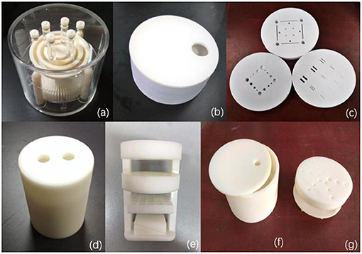
Figure 5. 3D-printed phantoms. (a) A 3D-printed MRI phantom with a 15 cm diameter PMMA shell, (b) a 3D-printed CT QC phantom with 20 cm diameter shell, (c) shows the customizable internal inserts of the CT QC phantom (d) a 3D-printed PET/MRI phantom with 6 cm diameter shell, (e) shows the customizable internal inserts of the PET/MRI phantom, (f) a 3D-printed PET/CT phantom with 9.3 cm diameter shell, (g) shows the customizable internal inserts of the PET/CT phantom.
After assembly, the phantom was filled with an appropriate test solution liquid or nuclear tracer, according to the requirement of the imaging mode. The phantoms were then scanned with a 3T MRI (Discovery MR750, GE, USA), CT (Brilliance-ICT, Philips, Netherlands), PET/MRI (NanoScan PET/MRI, Mediso, Hungary), and GE Discovery VCT (BGO PET+64 slices CT, GE, USA) for evaluation. The imaging parameters for MRI and CT scanners were time of repetition (TR) 2000 ms, time of echo (TE) 20 ms, 320 × 256 pixel size, slice thickness 5 mm for MR-SE sequence, and 120 kV, 25 mA, slice thickness 10 mm, and 320 × 256 pixel size for CT scans. Multi-modal PET/MRI imaging (Mediso, nanoScan PET/MRI) and PET/CT (GE Discovery VCT, USA) was performed with the 400–600 keV Energy Window, MRAC Attenuation Correction, and MRAC sequence, 13 mm slice, 600 ms TR, 9.7 TE 256 × 256 pixel size, and 80 kVp, Fixed-mA 20 mAs. Additionally, the ACR MRI phantom was scanned with a 3T MRI (Magnetom Verio, Siemens, Germany), the imaging parameters for MRI scanner were time of repetition (TR) 2000 ms, time of echo (TE) 20 ms, 320 × 256 pixel size, and slice thickness 5 mm for MR-SE sequence. The imaging parameters obtained from the assembled 3D phantoms were compared with traditional commercial phantoms (i.e., ACR MRI phantom, Catphan 500 phantom, and DSC PET Phantom).
Results
Physical Characteristics of Phantom Materials
Table 1 lists usage, shore hardness, density, porosity, and deformation temperature for the phantom materials used in this study (Verowhite, ABS P340, and MDT-White). Comparison values for typical commercially produced phantom materials, PMMA and silica gel, are also provided. All three printing materials have a shore hardness of 90. The physical densities of these materials are 1.15 g/cm3, 0.76 g/cm3, and 1.27 g/cm3, respectively. The porosities are 9.09, 6.81, and 18.56%, respectively. The threshold temperature of deformation for the three materials is >105°C, which is higher than that of PMMA and silica gel. Overall, compared with conventional phantom materials, 3D printing materials demonstrated superior waterproofing, physical stability, and temperature durability.
CT numbers and attenuation coefficients of the three printing materials are shown in Table 1, along with values for PMMA and silica gel. Based on the CT numbers of the printing materials, Verowhite (130 HU) was used for skeleton construction, ABS P340 (89 HU) was used for substrate and shell construction, and MDT-White (42 HU) was used for inserts and shell construction.
As shown in Table 2, physical dimensions of the inserts were measured using a screw micrometer and compared with the respective printing settings. MDT-White material measured less than the in silico CAD model, while ABS P340 and Verowhite measured slightly greater than the in silico CAD model. The 3D printed inserts had <5% variation in all three dimensions, and the variation is within the acceptable range.
Single Modality Imaging Scan
MRI scans of the assembled MRI phantom are shown in Figure 6. The sectional scans of the layer thickness test (a and b), MTF (c), high contrast resolution (d), geometric distortion test (e), and low contrast resolution (f) are also shown in Figure 6. Support pillars show no artifacts or interference signals. As a comparison, Figure 7 shows MRI sectional scans of the ACR MRI phantom, which includes the layer thickness test (a), MTF (b), high contrast resolution (c), geometric distortion test (d), and low contrast resolution (e). The functionality and image performance of our 3D printed MRI phantom are shown equivalent to the ACR MRI phantom.
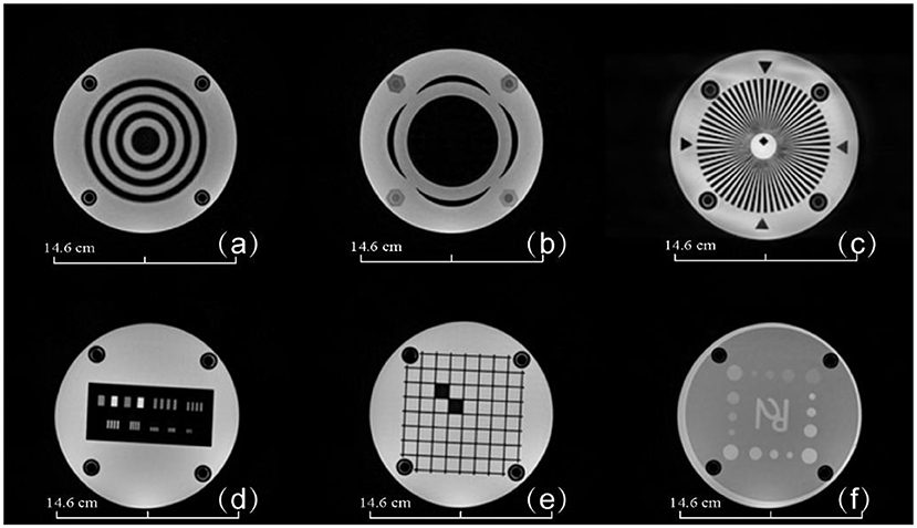
Figure 6. MRI images of the 3D-printed MRI phantom. (a) Layer thickness module, (b) layer thickness module, (c) star MTF test module, (d) high contrast resolution test module, (e) geometric distortion test module, (f) low contrast test module. Phantom dimensions are marked in the figure.
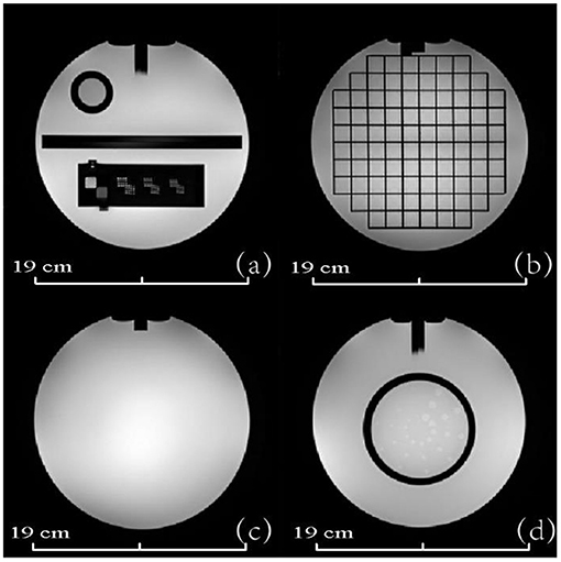
Figure 7. MRI images of the ACR MRI phantom. (a) Layer thickness and high contrast resolution module (b) geometric distortion test module (c) image uniformity module (d) low contrast test module. Phantom dimensions are marked in the figure.
Figure 8 shows transverse CT images from the CT phantom including high contrast resolution (a), uniformity (b), and layer thickness test (c). The standard deviation of the CT value uniformity test was <3 HU, which is comparable to that of a commercial phantom often used for CT scan routine QA. These CT results show that the 3D printed inserts have uniform density without imaging artifacts or interference.

Figure 8. CT images of the 3D-printed CT phantom. (a) High contrast resolution test layer, (b) uniformity test layer, and (c) thickness test layer. Phantom dimensions are marked in the figure.
Dual-Modality Imaging Scans
Figure 9 shows the transverse PET and MRI images from the assembled PET/MRI phantom for geometric distortion test (left column), high contrast resolution (middle column), and uniformity module (right column). PET images of two reconstruction algorithms are shown, including the Tera-Tomo reconstruction algorithm (a) and OSEM-Fore reconstruction algorithm (b). MRI images are shown in Figure 9C. Figure 10A shows high-uptake (hot) circles; Figure 10B shows dark circles. Both the hot and dark circles are clearly identified on these images. Dimension scales are shown at the image bottom for all figures.
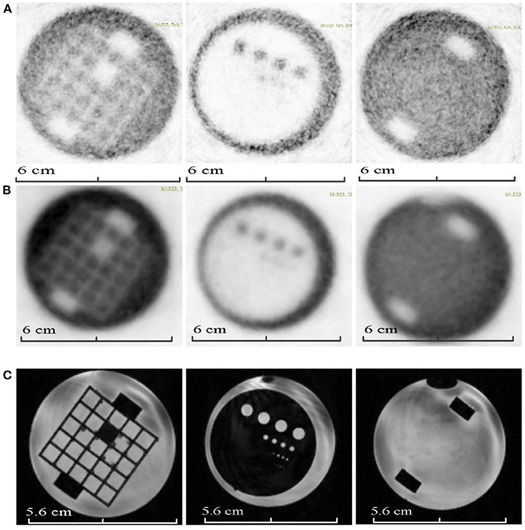
Figure 9. PET and MRI images of the 3D-printed PET/MR phantom modules (from left to right, geometric distortion test module, high contrast resolution module, and uniformity module). (A) Shows the PET images of the phantom based on Tera-Tomo reconstruction algorithm. (B) Shows the PET images of the phantom based on OSEM-Fore reconstruction algorithm. (C) Shows the MRI images of the phantom. Phantom dimensions are marked in the figure.
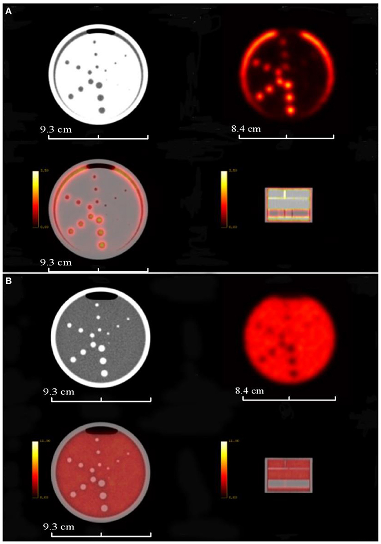
Figure 10. PET/CT images of the completely 3D-printed PET/CT phantom. (A) Shows the PET/CT image layer of the high-uptake circles; (B) shows the PET/CT image layer of the dark circles. First row shows CT and PET images, and the second row shows fused PET/CT images. Phantom dimensions are marked in the figure.
Imaging Tests Parameters
Table 3 summarizes the functionality of the constructed phantoms for MRI, CT, PET/MR, and PET/CT scanners for the required tests specified by the QC guidelines. The MRI phantom can be used for all required tests, while the CT phantom can be used for the primary relevant tests, including contrast resolutions, CT number uniformity, slice thickness, CT number accuracy, etc. For the PET/MR and PET/CT phantoms, the additional PET imaging required tests were added with the PET module. Table 4 summarizes the scanning results of these phantoms from their corresponding imaging modalities for QC tests, including high contrast resolution, low contrast resolution, uniformity, and deformation accuracy. All tests meet the criteria specified by the imaging QC guidelines.
Discussion
Our method used precisely designed and customized digital models to generate 3D printed imaging phantoms. This approach obviates the need for costly industrial molds to produce imaging phantoms for QA/QC testing. The proposed method also allows a wide range of modular phantom inserts to be assembled as needed for imaging QC across imaging platforms. Furthermore, the low cost of the 3D printed phantoms proposed in this study is estimated to be less than or equal to one tenth the cost of traditional commercial phantoms. The STL files for the proposed 3D printing phantom can be made available upon request to the corresponding authors.
Shore hardness, porosity, and deformation temperature are important characteristics of materials; compared with conventional PMMA derived phantoms, the 3D printing materials used have comparable material performance in terms of these characteristics. The porosity measured by NMR is usually applied to measuring mineral contents, and this technique can be utilized as an accurate and reliable tool to estimate the porosity of polymer materials, which include most 3D printing and PMMA materials [35–37]. The studied materials are for phantom use, instead of patient implants, and therefore we did not perform biocompatibility tests in the present study. In terms of long-term performance of the phantom, the aging characteristics show that the hot melt temperature of 3D printing materials is not lower than that of PMMA. Therefore, the 3D printing applied in this study has long-term stable physical properties. Repeated CT scans of the phantoms have demonstrated no significant change in the phantom structure, and the overall phantom deformation was shown to be <0.5 mm for all tested imaging modalities (Table 4). Further imaging studies of the phantom material for MR signal characterization and MR visibility is needed [38, 39].
Increased clinical utilization of multi-modal imaging necessitates the development of imaging phantoms suitable for multi-modality QA checks [39–42]. The proposed 3D printing approach overcomes technical limitations of conventional single modality QC phantoms by allowing for modality-directed phantom customization that can be rapidly altered based on the clinical QA/QC need. Additionally, the modular phantom design allows for incorporation of heterogeneous imaging inserts that provide high resolution, low deviation, and minimum assembly steps [38, 43, 44]. Tables 3, 4 showed imaging quality check parameters for the phantom tests in accordance with AAPM, ACR, and NEMA standards for CT, MRI, PET/MR, and PET/CT scanners.
It is worth noting that there are still technical issues for 3D printed phantoms. Currently the options of 3D printer materials are limited, and printer material selection can have a large impact on the quality of 3D printing medical imaging phantoms. Material selection for medical imaging phantoms should consider shore hardness, color, stability, and tissue equivalency. Further testing of more 3D printing materials is required to determine their quality for multi-modal QC imaging applications and susceptibility for image artifacts. Another limitation of the present study is lack of quantitative imaging analysis and evaluation for the phantom scans. The present paper focused mainly on the 3D printing material selection and their characteristics evaluation for the multi-model phantom construction. Image scans were acquired as a feasibility verification of the imaging quality. Further study is underway to include a more detailed quantitative imaging analysis for CT, MRI, and PET scans of the proposed phantom.
Conclusions
The 3D printed phantoms we designed, produced, and tested here demonstrated equivalent, if not better, QC imaging performance for CT, MRI, PET, and dual-modal imaging systems compared with commercial alternatives. In addition, 3D printed medical imaging phantoms provide a cost-efficient option and enable fast customization and implementation, which are especially valuable to clinics with hybrid imaging modality systems.
Data Availability Statement
The original contributions presented in the study are included in the article/supplementary material, further inquiries can be directed to the corresponding author.
Author Contributions
JQ and KH designed the phantoms and drafted a first manuscript version. J-CC helped with the imaging tests of the phantoms. BD and YR revised the manuscript critically and approved the final manuscript. LS, YS, LX, HZhao, and TC evaluated the resulting imaging of the phantoms. ZL, ML, FZ, and HZhan helped with the fabrication of the phantoms. All authors contributed to the article and approved the submitted version.
Funding
This work was supported by the China National Key Research and Development Program (2016YFC0103400), and JQ was supported by the Taishan Scholars Program of Shandong Province No. TS201712065.
Conflict of Interest
The authors declare that the research was conducted in the absence of any commercial or financial relationships that could be construed as a potential conflict of interest.
References
1. Dewerd LA, Kissick M. The phantoms of medical and health physics. Biol Med Phys Biomed Eng. (2014) 9:159–79. doi: 10.1007/978-1-4614-8304-5
2. Moores BM. Dosimetry and quality control in medical imaging applications. Ifmbe Proc. (2009) 25:359–62. doi: 10.1007/978-3-642-03902-7_101
3. Qiu J, Wang G, Min J, Wang X, Wang P. Testing the quality of images for permanent magnet desktop MRI systems using specially designed phantoms. Phys Med Biol. (2013) 58:8677. doi: 10.1088/0031-9155/58/24/8677
4. Ruben P, Harry S, Giorgos M, Adrian W, Koen M, Hilde B, et al. Development and applicability of a quality control phantom for dental cone-beam CT. J Appl Clin Med Phys. (2011) 12:3478. doi: 10.1120/jacmp.v12i4.3478
5. Huber JS, Peng Q, Moses WW. Multi-modality phantom development. IEEE Trans Nucl Sci. (2009) 56:2722–7. doi: 10.1109/TNS.2009.2028073
6. Reeve D. TU-SAM-304A-01: ACR MRI accreditation program update. Med Phys. (2009) 36:2715. doi: 10.1118/1.3182304
7. Yunker BE, Cordes D, Scherzinger AL, Dodd GD, Shandas R, Feng Y, et al. An investigation of industrial molding compounds for use in 3D ultrasound, MRI, and CT imaging phantoms. Med Phys. (2013) 40:52905. doi: 10.1118/1.4802083
8. Herrmann KH, Gärtner C, Güllmar D, Krämer M, Reichenbach JR. 3D printing of MRI compatible components: why every MRI research group should have a low-budget 3D printer. Med Eng Phys. (2014) 36:1373–80. doi: 10.1016/j.medengphy.2014.06.008
9. Morrison RJ, Kashlan KN, Flanangan CL, Wright JK, Green GE, Hollister SJ, et al. Regulatory considerations in the design and manufacturing of implantables 3d-printed medical devices. Clin Transl Sci. (2015) 8:594–600. doi: 10.1111/cts.12315
10. Niloufar Z, Jensen MD, Srikanth T, Foster PJ, Chambers AF, Dick FA, et al. Technical Note: Immunohistochemical evaluation of mouse brain irradiation targeting accuracy with 3D-printed immobilization device. Med Phys. (2015) 42:6507. doi: 10.1118/1.4933200
11. Adams F, Tian Q, Mark A, Fritz B, Kramer L, Schlager D, et al. Soft 3D-printed phantom of the human kidney with collecting system. Ann Biomed Eng. (2017) 45:963–72. doi: 10.1007/s10439-016-1757-5
12. Hazelaar C, Van EM, Dahele M, Wolff J, Forouzanfar T, Slotman B, et al. Using 3D printing techniques to create an anthropomorphic thorax phantom for medical imaging purposes. Med Phys. (2017) 45:92–100. doi: 10.1002/mp.12644
13. Zhang H, Hou K, Chen J, Dyer BA, Chen JC, Liu X, et al. Fabrication of an anthropomorphic heterogeneous mouse phantom for multimodality medical imaging. Phys Med Biol. (2018) 63:195011. doi: 10.1088/1361-6560/aadf2b
14. Daisne JF, Sibomana M, Bol A, Cosnard G, Lonneux M, Grégoire V. Evaluation of a multimodality image (CT, MRI and PET) coregistration procedure on phantom and head and neck cancer patients: accuracy, reproducibility and consistency. Radiother Oncol. (2003) 69:237–45. doi: 10.1016/j.radonc.2003.10.009
15. Bieniosek MF, Lee BJ, Levin CS (editors). 3D printing for cost-effective, customized, reusable multi-modality imaging phantoms. In: Nuclear Science Symposium & Medical Imaging Conference. Seoul (2013). p. 1–3. doi: 10.1109/NSSMIC.2013.6829187
16. Bieniosek MF, Lee BJ, Levin CS. Technical Note: Characterization of custom 3D printed multimodality imaging phantoms. Med Phys. (2015) 42:5913. doi: 10.1118/1.4930803
17. Kapetanakis I, Fountos G, Michail C, Valais I, Kalyvas N. 3D printing X-ray quality control phantoms. a low contrast paradigm. J Phys. (2017) 931:12026. doi: 10.1088/1742-6596/931/1/012026
18. Leng S, Mcgee K, Morris J, Alexander A, Kuhlmann J, Vrieze T, et al. Anatomic modeling using 3D printing: quality assurance and optimization. 3D Print Med. (2017) 3:6. doi: 10.1186/s41205-017-0014-3
19. Chen RK, Shih AJ. Multi-modality gellan gum-based tissue-mimicking phantom with targeted mechanical, electrical, and thermal properties. Phys Med Biol. (2013) 58:5511–25. doi: 10.1088/0031-9155/58/16/5511
20. Ehler ED, Barney BM, Higgins PD, Dusenbery KE. Patient specific 3D printed phantom for IMRT quality assurance. Phys Med Biol. (2014) 59:5763–73. doi: 10.1088/0031-9155/59/19/5763
21. Kamomae T, Shimizu H, Nakaya T, Okudaira K, Aoyama T, Oguchi H, et al. Three-dimensional printer-generated patient-specific phantom for artificial in vivo dosimetry in radiotherapy quality assurance. Phys Medica. (2017) 44:205–11. doi: 10.1016/j.ejmp.2017.10.005
22. Madamesila J, Mcgeachy P, Villarreal Barajas JE, Khan R. Characterizing 3D printing in the fabrication of variable density phantoms for quality assurance of radiotherapy. Phys Medica. (2016) 32:242–7. doi: 10.1016/j.ejmp.2015.09.013
23. Tran-Gia J, Schlogl S, Lassmann M. Design and fabrication of kidney phantoms for internal radiation dosimetry using 3D printing technology. J Nucl Med. (2016) 57:1998–2005. doi: 10.2967/jnumed.116.178046
24. Dickinson KJ, Cassivi SD, Reinersman JM, Matsumoto JS, Fletcher JG, Morris J, et al. Individualizing management of complex esophageal pathology using 3D printed anatomic models. Gastroenterology. (2015) 148:S-227–8. doi: 10.1016/S0016-5085(15)30750-2
25. Russ M, O'Hara R, Setlur Nagesh SV, Mokin M, Jimenez C, Siddiqui A, et al. Treatment planning for image-guided neuro-vascular interventions using patient-specific 3D printed phantoms. Proc Spie Int Soc Opt Eng. (2015) 9417:941726. doi: 10.1117/12.2081997
26. Torres K, Staskiewicz G, Sniezynski M, Drop A, Maciejewski R. Application of rapid prototyping techniques for modelling of anatomical structures in medical training and education. Folia Morphol. (2011) 70:1–4. doi: 10.1002/ar.21314
27. He Y, Liu Y, Dyer BA, Boone JM, Liu S, Chen T, et al. 3D-printed breast phantom for multi-purpose and multi-modality imaging. Quantit Imaging Med Surg. (2019) 9:63–74. doi: 10.21037/qims.2019.01.05
28. Coates GR, Marschall D, Mardon D, Galford J. A new characterization of bulk-volume irreducible using magnetic resonance. Log Analyst. (1997) 39:51–63.
29. Kleinberg RL, Boyd A. Tapered cutoffs for magnetic resonance bound water volume. Ann Tech Conference. (1997) 10:38737. doi: 10.2118/38737-MS
30. Li HB, Li Q, Yan ML. Influence of operation procedures on vicat softening temperature of thermoplastic materials. Adv Mater Res. (2011) 291–294:1820–4. doi: 10.4028/www.scientific.net/AMR.291-294.1820
32. Anashkin E, Matthews CG, Luo W editors. First test results of a commercially available clinical PET scanner using the NEMA NU 4 - 2008 small animal PET standards. In: Nuclear Science Symposium Conference Record. (2008). p. 4718–23.
33. Price RR, Axel L, Morgan T, Newman R, Perman W, Schneiders N, et al. Quality assurance methods and phantoms for magnetic resonance imaging: report of AAPM nuclear magnetic resonance Task Group No. 1. Med Phys. (1990) 17:287. doi: 10.1118/1.596566
34. Strauss KJ, Lin P-JP, Beck TJ, Borras C, Cohen G, Jucius RA, et al. Specification and Acceptance Testing of Computed Tomography Scanners. Report #39. New York, NY: American Association of Physicists in Medicine (1993).
35. Aqel MA. RESEARCH NOTE: permeability control on the relationship between nuclear magnetic resonance (NMR) measured porosity and routine core porosity. Arab J Geosci. (2016) 9:1–3. doi: 10.1007/s12517-016-2335-8
36. Hansen EW, Geir F, Ellen W. Pore morphology of porous polymer particles probed by NMR relaxometry and NMR cryoporometry. J Phys Chem B. (2005) 109:24295. doi: 10.1021/jp055175f
37. Komai T, Sakamoto Y, Nakashima Y, Takahara N, Minagawa H, Tenma N. NMR measurement and analysis of porosity and permeability for hydrate-bearing sediments. In: Proceedings of the Eighth ISOPE Ocean Mining Symposium Chennai. Tsukuba (2009). p. 1–6.
38. Mitsouras D, Lee TC, Liacouras P, Ionita CN, Pietilla T, Maier SE, et al. Three-dimensional printing of MRI-visible phantoms and MR image-guided therapy simulation. Magnet Reson Med. (2017) 77:613–22. doi: 10.1002/mrm.26136
39. Ng TSC, Bading JR, Park R, Sohi H, Procissi D, Colcher D, et al. Quantitative, simultaneous PET/MRI for intratumoral imaging with an MRI-compatible PET scanner. J Nucl Med. (2012) 53:1102–9. doi: 10.2967/jnumed.111.099861
40. Alssabbagh M, Tajuddin AA, Abdulmanap M, Zainon R. Evaluation of 3D printing materials for fabrication of a novel multi-functional 3D thyroid phantom for medical dosimetry and image quality. Radiat Phys Chem. (2017) 135:106–12. doi: 10.1016/j.radphyschem.2017.02.009
41. Keereman V, Mollet P, Fierens Y, Espana S, Vandenberghe S (editors). Design of a realistic PET-CT-MRI phantom. In: Nuclear Science Symposium and Medical Imaging Conference. Valencia (2012). p. 3173–7. doi: 10.1109/NSSMIC.2011.6153651
42. Pfluger T, Mueller WP. Combined PET/MRI in Childhood. New York, NY: Springer (2014). p. 597–620. doi: 10.1007/978-1-4614-9551-2_26
43. Homolka P, Figl M, Wartak A, Glanzer M, Dã¼Nkelmeyer M, Hojreh A, et al. Design of a head phantom produced on a 3D rapid prototyping printer and comparison with a RANDO and 3M lucite head phantom in eye dosimetry applications. Phys Med Biol. (2017) 62:3158–74. doi: 10.1088/1361-6560/aa602c
Keywords: multi-modality, phantom, 3D printing, quality control, medical imaging
Citation: Qiu J, Hou K, Dyer BA, Chen J-C, Shi L, Sun Y, Xu L, Zhao H, Li Z, Chen T, Li M, Zhang F, Zhang H and Rong Y (2021) Constructing Customized Multimodal Phantoms Through 3D Printing: A Preliminary Evaluation. Front. Phys. 9:605630. doi: 10.3389/fphy.2021.605630
Received: 14 September 2020; Accepted: 24 February 2021;
Published: 27 April 2021.
Edited by:
Ivo Rausch, Medical University of Vienna, AustriaReviewed by:
Francesco Moscato, Medical University of Vienna, AustriaRoberta Frass-Kriegl, Medical University of Vienna, Austria
Copyright © 2021 Qiu, Hou, Dyer, Chen, Shi, Sun, Xu, Zhao, Li, Chen, Li, Zhang, Zhang and Rong. This is an open-access article distributed under the terms of the Creative Commons Attribution License (CC BY). The use, distribution or reproduction in other forums is permitted, provided the original author(s) and the copyright owner(s) are credited and that the original publication in this journal is cited, in accordance with accepted academic practice. No use, distribution or reproduction is permitted which does not comply with these terms.
*Correspondence: Yi Rong, cm9uZy55aUBtYXlvLmVkdQ==
†These authors have contributed equally to this work
 Jianfeng Qiu
 Kun Hou
 Brandon A. Dyer2
 Liting Shi
 Zhengmei Li
 Haozhao Zhang
 Yi Rong


