 Xing Li
 Yuan Zhou
 Yanan Cai1,2
 Baoli Yao
94% of researchers rate our articles as excellent or good
Learn more about the work of our research integrity team to safeguard the quality of each article we publish.
Find out more
ORIGINAL RESEARCH article
Front. Phys. , 09 March 2021
Sec. Optics and Photonics
Volume 9 - 2021 | https://doi.org/10.3389/fphy.2021.591747
This article is part of the Research Topic Optical Trapping (Laser Tweezers) and Nanosurgery (Laser Scissors) View all 31 articles
Enabled by multiple optical traps, holographic optical tweezers can manipulate multiple particles in parallel flexibly. Spatial light modulators are widely used in holographic optical tweezers, in which Gaussian point (GP) trap arrays or special mode optical trap arrays including optical vortex (OV) arrays, perfect vortex (PV) arrays, and Airy beam arrays, etc., can be generated by addressing various phase holograms. However, the optical traps in these arrays are almost all of the same type. Here, we propose a new method for generating a hybrid optical trap array (HOTA), where optical traps such as GPs, OVs, PVs, and Airy beams in the focal plane are combined arbitrarily. Also, the axial position and peak intensity of each them can be adjusted independently. The energy efficiency of this method is theoretically studied, while different micro-manipulations on multiple particles have been realized with the support of HOTA experimentally. The proposed method expands holographic optical tweezers’ capabilities and provides a new possibility of multi-functional optical micro-manipulation.
Since the pioneering works of Ashkin [1, 2], optical tweezers have become a non-invasive technology for manipulating micro/nano particles. They have been widely used in physics, biology, medicine, and other fields [3–10]. Spatial light modulators (SLMs) have promoted the development of optical tweezers into a universal micro-manipulation tool [11], called holographic optical tweezers [12, 13], which surpass the original configuration of using a single laser spot to trap particles. SLMs use computer-generated-holograms (CGHs) to flexibly shape the wavefront of the laser beam, generating Gaussian point (GP) trap arrays or arrays of special optical modes, such as optical vortex (OV), perfect vortex (PV), and Airy beam. These are essential for a range of applications, including beam shaping, multi-beam laser processing, and optical micro-manipulation [14–17].
Due to the excellent flexibility of holographic beam shaping, complexly optical patterns can be tailored in favor of specific applications, such as high-resolution optical imaging, optical lithography, metamaterial manufacturing, and optical trapping and manipulation [14–21]. In holographic optical tweezers, the most commonly used light field distribution is the optical trap array. GP trap arrays can be realized by the Gerchberg-Saxton (GS) algorithm, weighted Gerchberg-Saxton (GSW) algorithm, and other improved iterative Fourier transform methods [22, 23]. Some unique methods were used to generate multifocal arrays, such as using fractional Talbot effect [24], two-dimensional (2D) pure-phase modulation gratings [25], and multizone phase plates [26], etc. OV arrays containing multiple vortices have been extensively studied [27–29]. Harshith et al. [30] used a dielectric microlens-array (MLA) and a plano-convex lens to generate OV arrays. OV arrays were also produced by interference methods [31–33]. In addition, the arrangement of multiple OVs can be a rectilinear, a square array [34], or along an arbitrary curve [35]. PV arrays were generated by various approaches, including the use of two-dimensional continuous phase gratings [36], and curved fork gratings [37]. Deng et al. [38] reported a three-dimensional (3D) PV array with high quality and uniform intensity by a special designed hybrid phase plate. Multiple Airy beams can also form arrays [39]. Jin et al. [40] defined a square array composed of four Airy beams, and each Airy beam can carry a different vortex. Qian et al. [41] developed a circular array consisting of multiple Airy beams. Moreover, hybrid arrays composed of GPs and OVs were reported [42, 43]. PV arrays composed of different topological charges were also generated by unique methods such as multi-zone plates and holographic gratings [44, 45]. However, it seems that little work has been reported on hybrid arrays composed of arbitrary combination of GPs, OVs, PVs, and Airy beams.
In this paper, we propose using the phase-only liquid crystal SLM to generate a hybrid optical trap array (HOTA), in which arbitrary combinations of optical traps such as GPs, OVs, PVs, and Airy beams appear in the focal plane simultaneously. We propose a new method to calculate the required CGH in the objective lens's back focal plane. By using the improved GSW algorithm to iterate all the holograms corresponding to the targeted traps, a single hologram that can produce the desired HOTA is obtained. The experimental measurement results are almost consistent with the intensity distributions obtained by the theoretical simulation. We studied the improvement of energy efficiency with the number of iterations, the movement of the axial position of the optical trap, and the change of peak intensity. We experimentally prove that our method can be applied to holographic optical tweezers, and may significantly expand their manipulation capabilities and provide a new possibility of multi-functional optical micro-manipulation.
The technique of using a computer-generated-hologram (CGH) or computer-designed diffractive optical element (DOE) to modulate the wavefront of the incident light field and then generating the target light field through Fourier transform is called holographic beam shaping [42, 46]. The principle is shown in Figure 1. The phase-only liquid crystal SLM acts as a DOE and displays a hologram to modulate the incident light field. The SLM is located on the back focal plane (Hologram plane) of the Fourier lens with a focal length of f. A combination of different optical traps, such as GPs, OVs, PVs, and Airy beams, etc., is generated near the front focal plane (Fourier plane). The OV carrying the orbital angular momentum (OAM) has a hollow intensity distribution, and the radius of its bright ring depends on the topological charge l. In contrast, the ring radius of the PV is independent of the topological charge. For the convenience of description, we use OVl and PVl to denote the OV and PV with a topological charge of l, respectively. The Airy beam has the characteristic of freely accelerating along a curved trajectory. The holograms addressed on the SLM and corresponding intensity patterns on the Fourier plane of the GP, OV+15, PV0, and Airy beam are shown in Figure 2.
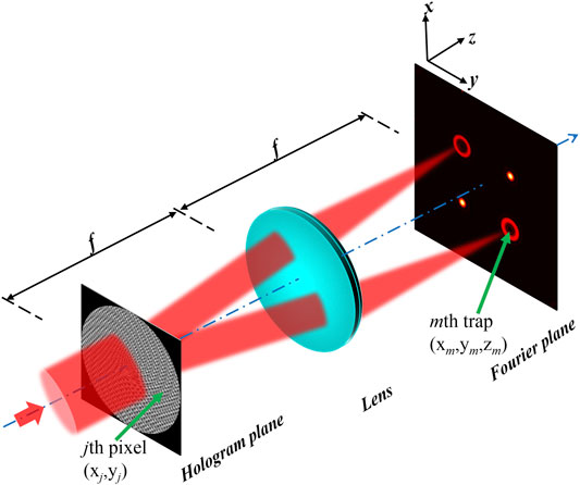
FIGURE 1. Schematic diagram of holographic beam shaping.
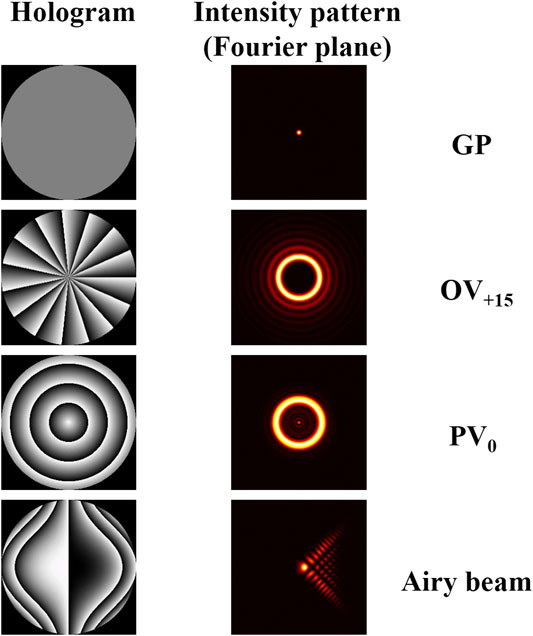
FIGURE 2. Holograms and intensity patterns of the Gaussian point (GP), optical vortex (OV+15), perfect vortex (PV0), and Airy beam.
Assume the incident optical field is a uniform plane wave with a unit amplitude of 1. After modulated by the SLM, the field’s complex amplitude at the jth pixel on the Hologram plane is
with
Here, λ is the wavelength of the incident light, d is the size of a single pixel of SLM, and N is the total number of pixels; f represents the focal length of the Fourier lens, (xj, yj), are the coordinates of the jth pixel on the Hologram plane, and (xm, ym, zm) are the coordinates of the mth optical trap. Since we deal with generic traps, not only point traps, an additional phase
Our primary objective is to seek the phase
where
Here wm is the weighting factor, and M is the total number of optical traps. Unlike the standard GSW, we have introduced a new parameter
The improved GSW algorithm, depicted in Figure 3, starts with the given
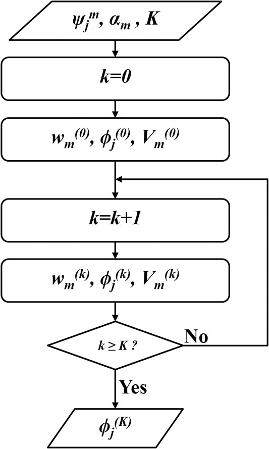
FIGURE 3. The flow chart of the improved GSW algorithm for HOTA.
Then the program enters iterative loops. In the kth iteration,
where
Figure 4 is an illustration of the holographic optical tweezers system used in our experiment. A linearly polarized laser beam (λ = 1064 nm) is expanded and collimated by a telescope composed of lenses L1 and L2. After passing through a half-wave plate (HWP) and a polarizing beam splitter (PBS), the input beam is polarized horizontally. The HWP adjusts the power of the laser. To miniaturize the experimental setup, a specially designed 96° prism is used to reflect the beam to the phase-only liquid crystal SLM (Pluto-HED6010-NIR-049-C, Holoeye Photonics AG Inc., Germany, 1,920 × 1,080 pixels, pixel pitch: 8.0 μm) while only the central area of 1,080 × 1,080 pixels (i.e., N = 1,080 × 1,080) is used. Lenses L3 and L4 form a 4f system, which relays the SLM plane to the back focal plane of the objective lens (Nikon Plan Apo IR, Japan, ×60, NA = 1.27, water immersion). The QWP is used to convert the linearly polarized beam into the circularly polarized one. After the objective lens focuses the beam, the required HOTA is observed in a region near the front focal plane. To map the intensity distribution of the generated field, a mirror M5, placed near the front focal plane, is employed to reflect the light to pass through in sequence objective lens, filter F and tube lens L5 and finally onto CMOS camera (Point Gray GS3-U3-41C6M-C, FLIR System Inc., United States, 2048 × 2,048 pixels, pixel pitch: 5.5 μm). When micro-manipulation experiments operate, the mirror M5 is replaced by a sample. The sample chamber consisting of double-sided tape, a cover-slip, and a slide, contains an aqueous solution of 2 μm in diameter polystyrene (PS) microspheres. Currently, there are already some softwares that can be used for optical trapping [49–51]. They can generate a variety of holograms and call the SLM to address holograms. In our experiment, we use MATLAB program to implement our proposed algorithm. After obtaining the hologram, the software provided by the SLM manufacturer is used to address the hologram. Simultaneously, the software also provides a method to correct the aberration, which is an essential factor that affects the quality of HOTA. The aberration of our system is mainly astigmatism caused by the uneven reflective surface of the SLM. In the commercial SLM software, we corrected that to improve the quality and manipulation performance of the HOTA by using the preset Zernike polynomials.
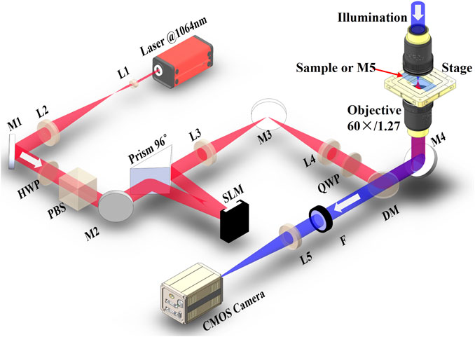
FIGURE 4. Schematic diagram of the holographic optical tweezers system used to generate HOTAs. L, lens; M, mirror; HWP, half-wave plate; PBS, polarizing beam splitter; QWP, quarter-wave plate; DM, dichroic mirror; F, filter; SLM, spatial light modular; CMOS, complementary metal oxide semiconductor.
We first generate an array composed of four types of optical traps: GPs, OVs, PVs, and Airy beams, as shown in Figure 5. Figure 5A shows
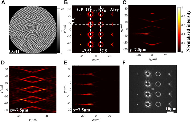
FIGURE 5. An array composed of four types of optical traps: GPs, OVs, PVs, and Airy beams. (A) Hologram addressed on SLM. (B) The intensity distribution of the xy-plane obtained by the simulation. (C) The intensity distribution of the xz-plane obtained by the simulation corresponding to the dashed line y = 7.5 μm in (B). (D,E) The intensity distributions in yz-plane obtained by simulation corresponding to the dashed line x = −7.5 μm and x = 7.5 μm in (B), respectively. (F) The intensity distribution of the xy-plane obtained from the experiment. The center highlight is the zero-order spot of SLM.
We next investigate the energy efficiency of the proposed HOTA and define that as [48].
It measures the ratio of the energy diffracted to all M optical traps to the incident energy. Higher energy efficiency means more energy is used and less energy is diffracted into ghost traps. The traditional GSW algorithm can improve the energy efficiency of multiple optical traps through iterations. Here, the improved GSW also helps to increase the light energy utilization. Figure 6 shows that as the number of iterations increases, the light energy is gradually concentrated into the designed optical traps. The energy efficiency is gradually increased from ∼0.55 at the beginning of the iteration to ∼0.907 after 30 iterations. In this example, the average time for each iteration is ∼0.67 s on our computer (Intel Core i5 CPU 760@2.80GHz). After 16 iterations, energy efficiency no longer increases, indicating that the algorithm has converged.
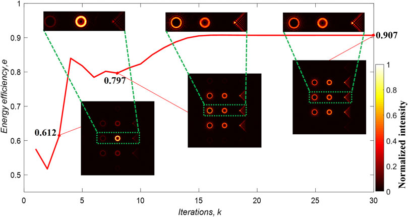
FIGURE 6. The behavior of energy efficiency is shown as a function of the number of iterations. After 3, 8, and 30 iterations, the energy efficiency becomes 0.612, 0.797, and 0.907, respectively. In the bottom insets, the first to third columns of each one are OVs with l = +15, PVs with l = +5, and Airy beams, respectively.
In Eq. 2, the coordinates of the optical trap m are xm, ym, and zm, which can be changed to adjust three-dimensional (3D) positions of optical traps. xm and ym can adjust positions of optical traps in the xy-plane. They change the lateral distance between optical traps. In order to show that the proposed method can control the three-dimensional position of optical traps, we change zm to adjust the axial position of optical traps. In Figure 7, the optical traps in the red, green and blue dashed areas are located at z = −15 μm, z = 0, and z = 15 μm, respectively. The simulation results demonstrate that different holograms can be used to make optical traps move along the optical axis. Combined with the movement in the lateral plane, the generated HOTA can realize the control of the 3D position.
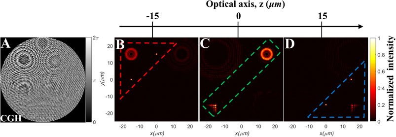
FIGURE 7. The generated hybrid optical traps at different axial positions. (A) Hologram. (B) A PV+5 and two GPs inside the red dashed line, located in the plane of z = −15 μm. (C) A PV-5 and an Airy beam inside the green dashed line, located in the plane of z = 0. (D) An Airy beam and two GPs inside the blue dashed line, located in the plane of z = +15 μm.
The ability to regulate the energy ratio between multiple optical traps allows researchers to customize force magnitude flexibly. Xu et al. [52] used a complementary random phase encoding technique to separately regulate each trap energy of multiple traps. However, all optical traps are Gaussian point traps, which are different from the HOTA we need as it contains various types of optical traps. If the GSW algorithm in [48] is used directly (that is, all types of beams are weighted equally), the energy allocated to GPs, OVs, PVs, and Airy beams will be equal. However, in the optical trapping and manipulation experiments, GPs and Airy traps demand much lower working energy than the OVs and PVs. Therefore, it is necessary to make the energy of different types of beams unequal. In order to achieve this goal, we introduce a new parameter
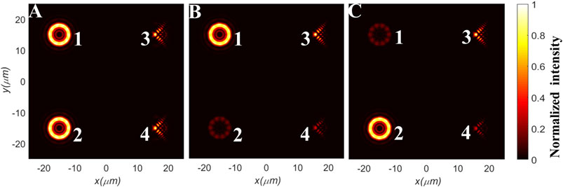
FIGURE 8. Adjusting the peak intensity of different optical traps. (A) The peak intensities of the four optical traps are approximately equal. α1, α2, α3, and α4 are 2.6, 2.6, 1, and 1, respectively. (B) Keep the peak intensities of optical traps 1 and 3, while the peak intensities of optical traps 2 and 4 are relatively weakened. α1, α2, α3, and α4 are 2.6, 1.3, 1, and 0.5, respectively. (C) Keep the peak intensities of optical traps 2 and 3, while the peak intensities of optical traps 1 and 4 are relatively weakened. α1, α2, α3, and α4 are 1.3, 2.6, 1, and 0.5, respectively.
Figures 9B,C show the simulation and experimental results for a trap array: four vortices (OV+15, PV+10, OV−15, and PV−10) and four GPs. From Figures 9D–I, the difference between the direction of rotation among different vortices can be seen: OV+15 and PV+10 trap PS microspheres and rotate them counterclockwise, while OV−15 and PV−10 give rise to an opposite rotational sense. Each of the four GPs traps a PS microsphere, and the zero-order diffracted focal spot (center) also traps a PS microsphere. But each GP can also trap more than one PS microsphere (see the Supplementary Material Video S1). In Figures 9D–I, the optical trap in the upper left corner (OV+15) drives the PS microsphere to rotate counterclockwise, and it takes about 0.42 s to complete one full cycle. The optical trap in the lower right corner (PV+10) drives the PS microsphere to rotate counterclockwise and takes about 0.46 s per cycle. Our experimental results on trapping and manipulating micro-particles demonstrate that HOTA can provide multiple types of manipulation simultaneously.
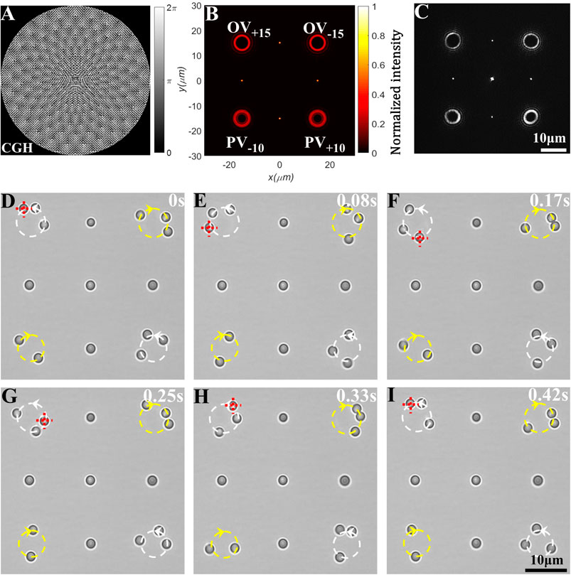
FIGURE 9. Various types of manipulation of PS microspheres with HOTA by holographic optical tweezers. (A) Hologram addressed on SLM. (B) The intensity pattern in the focal plane obtained by simulation, which is composed of OV±15, PV±10, and 4 GPs. (C) The intensity pattern in the focal plane measured experimentally. The bright spot in the center is the zero-order beam of the SLM. (D–I) Snapped video frames of manipulating PS microspheres at a sequential time point. At the optical trap of OV+15 in the upper left corner, the PS microspheres undergo a counterclockwise rotation of about 0.42 s per cycle.
We have proposed a method for generating a hybrid optical trap array. Addressing a hologram on the phase-only SLM can generate various types of optical traps near the focal plane of the objective lens. Our simulation results reveal that the energy efficiency can be improved by increasing the number of iterations and stabilized after a dozen iterations. The optical traps' axial positions can be independently controlled, and multiple optical traps are located on different planes. The peak intensity of the optical traps can be adjusted by the parameter
The original contributions presented in the study are included in the article/Supplementary Material, further inquiries can be directed to the corresponding author.
XL conceived the idea. XL, YuZ, and YC constructed the experimental setup and experimented. YaZ, SY, ML, and RL contributed to discussing the results and the theoretical simulation. XL wrote and edited the manuscript. BY supervised the study. All the authors reviewed and revised the manuscript.
National Natural Science Foundation of China (NSFC) (11974417 and 11904395).
The authors declare that the research was conducted in the absence of any commercial or financial relationships that could be construed as a potential conflict of interest.
The Supplementary Material for this article can be found online at: https://www.frontiersin.org/articles/10.3389/fphy.2021.591747/full#supplementary-material.
1. Ashkin A. Acceleration and trapping of particles by radiation pressure. Phys Rev Lett (1970) 24:156–9. doi:10.1103/physrevlett.24.156
2. Ashkin A, Dziedzic JM, Bjorkholm JE, Chu S. Observation of a single-beam gradient force optical trap for dielectric particles. Opt Lett (1986) 11:288–90. doi:10.1364/OL.11.000288
3. Chu S. Nobel Lecture: the manipulation of neutral particles. Rev Mod Phys (1998) 70:685–706. doi:10.1103/REVMODPHYS.70.685
4. Phillips WD. Nobel Lecture: laser cooling and trapping of neutral atoms. Rev Mod Phys (1998) 70:721–41. doi:10.1103/REVMODPHYS.70.721
5. Diekmann R, Wolfson DL, Spahn C, Heilemann M, Schüttpelz M, Huser T. Nanoscopy of bacterial cells immobilized by holographic optical tweezers. Nat Commun (2016) 7:13711. doi:10.1038/NCOMMS13711
6. Landenberger B, Höfemann H, Wadle S, Rohrbach A. Microfluidic sorting of arbitrary cells with dynamic optical tweezers. Lab Chip (2012) 12:3177–83. doi:10.1039/C2LC21099A
7. McAlinden N, Glass DG, Millington OR, Wright AJ. Accurate position tracking of optically trapped live cells. Biomed Opt Express (2014) 5:1026–37. doi:10.1364/BOE.5.001026
8. Perkins T, Quake SR, Smith DE, Chu S. Relaxation of a single DNA molecule observed by optical microscopy. Science (1994) 264:822–6. doi:10.1126/SCIENCE.8171336
9. Neuman KC, Nagy A. Single-molecule force spectroscopy: optical tweezers, magnetic tweezers and atomic force microscopy. Nat Methods (2008) 5:491–505. doi:10.1038/NMETH.1218
10. Polimeno P, Magazzù A, Iatì MA, Patti F, Saija R, Boschi CDE, et al. Optical tweezers and their applications. J Quant Spectrosc Radiat Transfer (2018) 218:131–50. doi:10.1016/J.JQSRT.2018.07.013
11. Forbes A, Dudley A, McLaren M. Creation and detection of optical modes with spatial light modulators. Adv Opt Photon (2016) 8:200–27. doi:10.1364/AOP.8.000200
12. Grier DG. A revolution in optical manipulation. Nature (2003) 424:810–6. doi:10.1038/NATURE01935
13. Dholakia K, MacDonald M, Spalding G. Optical tweezers: the next generation. Phys World (2002) 15:31–5. doi:10.1088/2058-7058/15/10/37
14. Obata K, Koch J, Hinze U, Chichkov BN. Multi-focus two-photon polymerization technique based on individually controlled phase modulation. Opt Express (2010) 18:17193–200. doi:10.1364/OE.18.017193
15. Gan Z, Cao Y, Evans RA, Gu M. Three-dimensional deep sub-diffraction optical beam lithography with 9 nm feature size. Nat Commun (2013) 4:2061. doi:10.1038/NCOMMS3061
16. Paterson L, MacDonald MP, Arlt J, Sibbett W, Bryant PE, Dholakia K. Controlled rotation of optically trapped microscopic particles. Science (2001) 292:912–4. doi:10.1126/SCIENCE.1058591
17. Woerdemann M, Alpmann C, Esseling M, Denz C. Advanced optical trapping by complex beam shaping. Laser Photon Rev (2013) 7:839–54. doi:10.1002/LPOR.201200058
18. Shao Y, Qu J, Li H, Wang Y, Qi J, Xu G, et al. High-speed spectrally resolved multifocal multiphoton microscopy. Appl Phys B: Lasers Opt (2010) 99:633–7. doi:10.1007/S00340-010-4066-Y
19. Arai Y, Yasuda R, Akashi K, Harada Y, Miyata H, Kinosita K, et al. Tying a molecular knot with optical tweezers. Nature (1999) 399:446–8. doi:10.1038/20894
20. Jia B, Kang H, Li J, Gu M. Use of radially polarized beams in three-dimensional photonic crystal fabrication with the two-photon polymerization method. Opt Lett (2009) 34:1918–20. doi:10.1364/OL.34.001918
21. Zhuang X. Molecular biology. Unraveling DNA condensation with optical tweezers. Science (2004) 305:188–90. doi:10.1126/SCIENCE.1100603
22. Duadi H, Zalevsky Z. Optimized design for realizing a large and uniform 2-D spot array. J Opt Soc Am A Opt Image Sci Vis (2010) 27:2027–32. doi:10.1364/JOSAA.27.002027
23. Kim D, Keesling A, Omran A, Levine H, Bernien H, Greiner M, et al. Large-scale uniform optical focus array generation with a phase spatial light modulator. Opt Lett (2019) 44:3178–81. doi:10.1364/OL.44.003178
24. Zhu L, Yu J, Zhang D, Sun M, Chen J. Multifocal spot array generated by fractional Talbot effect phase-only modulation. Opt Express (2014) 22:9798–808. doi:10.1364/OE.22.009798
25. Zhu L, Sun M, Zhu M, Chen J, Gao X, Ma W, et al. Three-dimensional shape-controllable focal spot array created by focusing vortex beams modulated by multi-value pure-phase grating. Opt Express (2014) 22:21354–67. doi:10.1364/OE.22.021354
26. Mu T, Chen Z, Pacheco S, Wu R, Zhang C, Liang R. Generation of a controllable multifocal array from a modulated azimuthally polarized beam. Opt Lett (2016) 41:261–4. doi:10.1364/OL.41.000261
27. Liu J, Min C, Lei T, Du L, Yuan Y, Wei S, et al. Generation and detection of broadband multi-channel orbital angular momentum by micrometer-scale meta-reflectarray. Opt Express (2016) 24:212–8. doi:10.1364/OE.24.000212
28. Yu J, Zhou C, Jia W, Hu A, Cao W, Wu J, et al. Generation of dipole vortex array using spiral Dammann zone plates. Appl Opt (2012) 51:6799–804. doi:10.1364/AO.51.006799
29. Lin YC, Lu TH, Huang KF, Chen YF. Generation of optical vortex array with transformation of standing-wave Laguerre-Gaussian mode. Opt Express (2011) 19:10293–303. doi:10.1364/OE.19.010293
30. Harshith BS, Samanta GK. Controlled generation of array beams of higher order orbital angular momentum and study of their frequency-doubling characteristics. Sci Rep (2019) 9:10916. doi:10.1038/S41598-019-47403-1
31. Vaity P, Aadhi A, Singh RP. Formation of optical vortices through superposition of two Gaussian beams. Appl Opt (2013) 52:6652–6. doi:10.1364/AO.52.006652
32. Huang S, Miao Z, He C, Pang F, Li Y, Wang T. Composite vortex beams by coaxial superposition of Laguerre–Gaussian beams. Opt Lasers Eng (2016) 78:132–9. doi:10.1016/J.OPTLASENG.2015.10.008
33. Vyas S, Senthilkumaran P. Interferometric optical vortex array generator. Appl Opt (2007) 46:2893–8. doi:10.1364/AO.46.002893
34. Fu S, Wang T, Zhang Z, Zhai Y, Gao C. Selective acquisition of multiple states on hybrid poincare sphere. Appl Phys Lett (2017) 110:191102. doi:10.1063/1.4983284
35. Li L, Chang C, Yuan X, Yuan C, Feng S, Nie S, et al. Generation of optical vortex array along arbitrary curvilinear arrangement. Opt Express (2018) 26:9798–812. doi:10.1364/OE.26.009798
36. Yu J, Zhou C, Lu Y, Wu J, Zhu L, Jia W. Square lattices of quasi-perfect optical vortices generated by two-dimensional encoding continuous-phase gratings. Opt Lett (2015) 40:2513–6. doi:10.1364/OL.40.002513
37. Karahroudi MK, Parmoon B, Qasemi M, Mobashery A, Saghafifar H. Generation of perfect optical vortices using a Bessel-Gaussian beam diffracted by curved fork grating. Appl Opt (2017) 56:5817–23. doi:10.1364/AO.56.005817
38. Deng D, Li Y, Han Y, Su X, Ye J, Gao J, et al. Perfect vortex in three-dimensional multifocal array. Opt Express (2016) 24:28270–8. doi:10.1364/OE.24.028270
39. Yu X, Li R, Yan S, Yao B, Gao P, Han G, et al. Experimental demonstration of 3D accelerating beam arrays. Appl Opt (2016) 55:3090–5. doi:10.1364/AO.55.003090
40. Jin L, Li H, Zhao C, Gao W. Generation of airy vortex beam arrays using computer-generated holography. J Opt Soc Am A-Opt Image Sci Vis (2019) 36:1215–20. doi:10.1364/JOSAA.36.001215
41. Qian Y, Shi Y, Jin W, Hu F, Ren Z. Annular arrayed-Airy beams carrying vortex arrays. Opt Express (2019) 27:18085–93. doi:10.1364/OE.27.018085
42. Curtis JE, Koss BA, Grier DG. Dynamic holographic optical tweezers. Opt Commun (2002) 207:169–75. doi:10.1016/S0030-4018(02)01524-9
43. Moreno I, Davis JA, Cottrell DM, Zhang N, Yuan XC. Encoding generalized phase functions on Dammann gratings. Opt Lett (2010) 35(10):1536–8. doi:10.1364/OL.35.001536
44. Deng D, Li Y, Han Y, Ye J, Guo Z, Qu S. Multifocal array with controllable orbital angular momentum modes by tight focusing. Opt Commun (2017) 382:559–64. doi:10.1016/j.optcom.2016.08.049
45. Fu S, Wang T, Gao C. Perfect optical vortex array with controllable diffraction order and topological charge: erratum. J Opt Soc Am A Opt Image Sci Vis (2016) 33:2076–1842. doi:10.1364/JOSAA.33.001836
46. Liesener J, Reicherter M, Haist T, Tiziani HJ. Multi-functional optical tweezers using computer-generated holograms. Opt Commun (2000) 185:77–82. doi:10.1016/S0030-4018(00)00990-1
48. Leonardo RD, Ianni F, Ruocco G. Computer generation of optimal holograms for optical trap arrays. Opt Express (2007) 15:1913–22. doi:10.1364/OE.15.001913
49. Preece D, Bowman R, Gibson G, Padgett M. A comprehensive software suite for optical trapping and manipulation. Proc SPIE (2009) 7400. doi:10.1117/12.826924
50. Lenton ICD, Stilgoe AB, Nieminen TA, Rubinsztein-Dunlop H. OTSLM toolbox for structured light methods. Comput Phys Commun (2020) 253:107199. doi:10.1016/J.CPC.2020.107199
51. Sinclair G, Leach J, Jordan P, Gibson G, Yao E, Laczik Z, et al. Interactive application in holographic optical tweezers of a multi-plane Gerchberg-Saxton algorithm for three-dimensional light shaping. Opt Express (2004) 12(8):1665–70. doi:10.1364/OPEX.12.001665
Keywords: holographic optical tweezers, hologram, spatial light modulator, hybrid optical trap array, optical trapping
Citation: Li X, Zhou Y, Cai Y, Zhang Y, Yan S, Li M, Li R and Yao B (2021) Generation of Hybrid Optical Trap Array by Holographic Optical Tweezers. Front. Phys. 9:591747. doi: 10.3389/fphy.2021.591747
Received: 05 August 2020; Accepted: 19 January 2021;
Published: 09 March 2021.
Edited by:
Michael W. Berns, University of California, Irvine, United StatesReviewed by:
Nirmal Mazumder, Manipal Academy of Higher Education, IndiaCopyright © 2021 Li, Zhou, Cai, Zhang, Yan, Li, Li and Yao. This is an open-access article distributed under the terms of the Creative Commons Attribution License (CC BY). The use, distribution or reproduction in other forums is permitted, provided the original author(s) and the copyright owner(s) are credited and that the original publication in this journal is cited, in accordance with accepted academic practice. No use, distribution or reproduction is permitted which does not comply with these terms.
*Correspondence: Baoli Yao, eWFvYmxAb3B0LmFjLmNu
Disclaimer: All claims expressed in this article are solely those of the authors and do not necessarily represent those of their affiliated organizations, or those of the publisher, the editors and the reviewers. Any product that may be evaluated in this article or claim that may be made by its manufacturer is not guaranteed or endorsed by the publisher.
Research integrity at Frontiers
Learn more about the work of our research integrity team to safeguard the quality of each article we publish.