 Koki Hasegawa1,2
 Shinji Takayanagi
 Iwaki Akiyama
- 1Medical Ultrasound Research Center, Doshisha University, Kyotanabe, Japan
- 2Department of Biomedical Sciences and Informatics, Faculty of Life and Medical Sciences, Doshisha University, Kyotanabe, Japan
A flexible-shaped ultrasonic array probe that can be used in a high magnetic field environment in an MRI gantry has been developed. Given that this probe can be fixed according to the shape of the skull’s surface, it is particularly applicable for imaging in the brain. To perform ultrasonic beamforming using a bent probe, it is necessary to measure the bent shape. Therefore, in this research, the curvature of the probe was estimated using MRI. A phantom with ellipse surface close to the shape of a skull was created using a 3D printer. The probe was arranged along the phantom surface to perform MRI and ultrasonic beamforming. The ultrasonic array transducer had 192 elements made from 1-3 composite piezoelectric materials with an element spacing of 0.3 mm. Eight MR position markers were attached to the probe in parallel in two rows of four each, with the array transducer in between. The delay time of each element in dynamic focusing for reception was calculated from its position estimated by the curvature of the probe. To evaluate the feasibility of this method, a B-mode image of 0.98 mm-diameter-thread targets placed in water was generated. The beam width at half maximum of the echo peak in the lateral direction from the thread target set up near the transmission focal point was calculated based on the B-mode image. It was found that the beam width of 1.32 mm in the proposed method, which was close to the thread diameter, whereas that was 4.38 mm in the conventional method that did not consider the bending of the probe. Consequently, the proposed beamforming technique is feasible for ultrasonic imaging through an arbitrary curved surface. Practical applications with a head phantom mimicking skull and cerebral tissue are expected.
Introduction
As typical clinical diagnosis, computed tomography (CT), magnetic resonance imaging (MRI), positron emission tomographic (PET), and ultrasonic imaging are widely used [1]. Ultrasonic diagnostic equipment is especially an indispensable medical imaging device for the diagnosis of pathological conditions because of its non-invasion, portability, and short examination time. Recently, the target of the ultrasonic equipment expands to brain tissues. S.T. Brinker et al. reported the virtual brain projection for the trans-skull beam behavior of transcranial ultrasonic equipment, which is significant to access the brain tissues [2]. V. Ozenna et al demonstrated that simultaneous measurement of thermal rise and displacement in the brain by a focus ultrasonic transcranial approach with a single-element transducer [3]. They achieved an acoustic coupling of the transducer with the head by a water-filled inflatable balloon. On the other hand, ultrasonic B-mode images of the brain with blood flow representation were performed around 1990 [4]. They propagated ultrasonic waves through an area bounded by the zygomatic process and the inferior temporal line by using a phased-array transducer with 48 elements. One way to further improve the lateral resolution of ultrasound images is to increase the number of transducer elements. However, the larger probe size makes it difficult to contact the flat surface of the parietal or temporal area. To efficiently propagate the ultrasonic waves to the brain in practice, it is necessary to bend the ultrasonic probe along the skull and bring it into close contact. In our previous study, a flexible-type ultrasonic array probe with 192 elements was developed [5]. It can be bent along curved surfaces such as the human body and skull. An ultrasonic B-mode image with a conventional flat-type array probe is obtained by the calculation of the delay time of the ultrasonic wave reaching each element arranged on a straight line. In the case of the flexible-type probe, the ultrasonic B-mode image is degraded unless the delay time according to the bending is considered. The correction of the B-mode image to such bending, however, has not been examined. Therefore, measurement of the bending shape and ultrasonic beamforming are required.
MRI has the advantages of a multi-planar imaging capability, a high signal-to-noize ratio (SNR), and sensitivity to subtle changes in soft tissue morphology and function [6]. Taking advantage of these properties, ultrasound medical technology has been combined with MRI technology. MR-guided focused ultrasound has been researched such as a non-invasive and effective approach to generation of focal intracranial lesions [7]. MRI is used for a measurement of the transducer position to the skull and the identification of the focus point in the brain [3]. Multimodality imaging, which combines MR and ultrasound images, on the other hand, is performed to improve the spatial and temporal resolution of each other's data [6]. It has been applied to neuronavigation [8] and prostate biopsy [9].
In this study, the bent shape of the flexible-type probe was estimated by MRI. Although it is possible to estimate the shape from optical images instead of MR images, it can be easily introduced into medical institutions by using the widely used MRI technology. Furthermore, it is expected to be applied to the multimodality imaging. Our flexible-type ultrasonic array probe can be used in a high magnetic field environment in an MRI gantry [5], and MR-visible position markers [10] are attached to the probe to facilitate the estimation of the shape. MRI was performed with the flexible probe fixed along bent surface of a phantom simulated the curvature of the skull in this experiment. The curvature of the phantom was estimated with a quadratic function by the MR images. Then, ultrasonic echo signals from nylon threads set in water were observed by the probe fixed along the phantom surface. The B-mode image of the thread targets was obtained by the calculation of the delay time assigned to each element in view of the curvature of the phantom. The effect of the correction on the B-mode image was described by comparison with the image without reference to the bending shape.
Methods and Materials
Flexible-Type Ultrasonic Array Probe and Curved Surface Phantom
A flexible-type ultrasonic array probe (Japan Probe, Kyokutan, Yokohama, Japan) used in this study was shown in Figure 1A. It was made of non-magnetic materials so that it can be used in MRI high magnetic fields. In addition, it was equipped with MR-visible fiducial markers to estimate its bent surface curvature. Eight markers were arranged in two rows of four each. They were an acrylic cylinder filled with olive oil with a diameter of 9.00 mm and a height of 8.50 mm, containing a 6.35 mm polyoxymethylene (POM) sphere [5]. When they were imaged using MRI, a high-luminance cylindrical area and a low-luminance spherical area were displayed. The geometric center positions of the spherical area were then calculated as the coordinates of the marker in the MR 3D image. The array transducer was fixed along the centerline between the two rows of the markers. It had 192 elements cut from 1-3 composite piezoelectric materials [11, 12] with an element spacing of 0.3 mm.
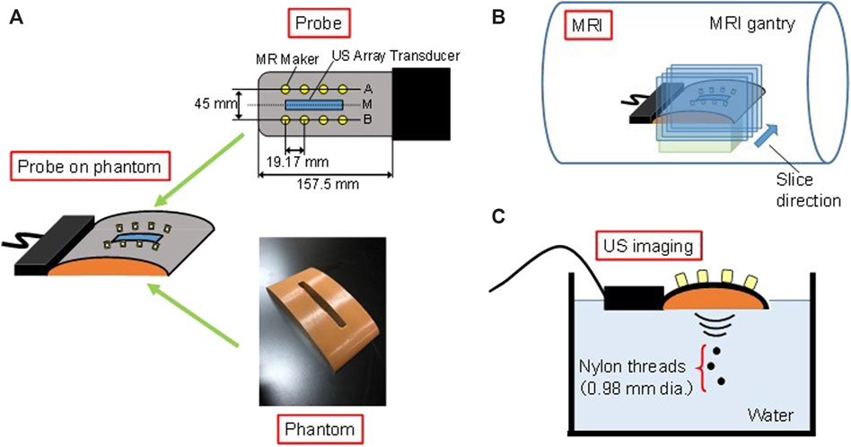
FIGURE 1. (A) Flexible-type ultrasonic array probe and curved surface phantom, and experimental set up with the bent probe on the phantom in (B) MRI and (C) ultrasonic imaging.
A curved surface phantom for bending of the probe was prepared by a 3D printer, as shown in Figure 1A. The curvature of the phantom surface was designed by the following equation,
where x and y are coordinates in millimeters. The origin of Eq. 1 is at the vertex of the curve. It is a curve close to the parietal bone surface of an adult male within the size of the array transducer. The parietal bone surface was simply approximated to an ellipse for the phantom preparation in this experiment. Because the bending of the probe is approximated by a polynomial based on MR images, our proposed method is not limited to the application to elliptical surfaces. To easily consider the effects of bending on the ultrasonic imaging, the rectangular hole was made as a window for the ultrasonic transmission from the array transducers to the targets. The probe was attached on the curved surface of the phantom. In the following experiments, the probe in this bent state was used.
Estimation of Prove Curvature Using Magnetic Resonance Imaging
The curvature of the array transducer by bending the ultrasonic probe along the phantom was estimated using MR images. MRI was performed with the probe fixed on the phantom in the MRI room. The probe was attached to the phantom with adhesive tape. It does not affect the system response as it was adhered at the non-transducer part. MR marker positions were detected from the series of cross-sectional images obtained via MRI machine (Echelon Vega, 1.5T, Hitachi Co., Tokyo, Japan) as shown in Figure 1B. Table 1 shows MRI scan parameters. The cross section of MR images included planes through the marker row, which was shown as line A or B in Figure 1A, and perpendicular to the probe surface. They were parallel to the cross section of ultrasonic B-mode image.
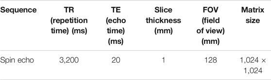
TABLE 1. MRI scan parameters.
The algorithm for the coordinate estimation of the marker centers is as follows; 1) binarization of a MR image for discriminant analysis; 2) filling the cavity of the binarized image; 3) deletion of the marker region in the opening process; 4) obtaining an image with only the markers by taking the difference between the image in 2) and the image in 3); and 5) labeling and specification of the marker position to the geometric center. The process for the detection of the marker locations was conducted on all cross-sectional MR images to identify the number and position of the markers in each cross-section. The detection data which was away from the marker size was excluded. To prevent false detection, a smoothing filter was applied during the labeling process depending on the size and position of the marker. Four midpoint coordinates on the center line M in Figure 1A were calculated from the eight marker coordinates in the two rows. The curvature of the array transducer was then approximated by a quadratic function in a two-dimensional plane from the midpoint coordinates.
Acquisition of Ultrasonic Echo Signals
Ultrasonic echo signals were observed using the bent probe for the B-mode image generation. The probe was fixed on the phantom in the same manner in the acquisition of the MR images. Three nylon threads with 0.98 mm diameter were set in water as targets, as shown in Figure 1C. A plane including the radial directions of the threads corresponded to the cross section of the B-mode image. Table 2 shows specifications of the ultrasonic imaging equipment. The transmitted ultrasonic waves were burst signals of 1.5 sinusoidal waves with a center frequency of 5.0 MHz. Beamforming was employed simultaneously using 128 channels of 192 transducer elements. The transmission focus was set at 30 mm in the depth direction. The echo data were acquired three times.
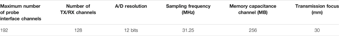
TABLE 2. Specifications of ultrasonic imaging equipment.
Dynamic Focusing for Bent Array Transducer
The image formation technique used in a general ultrasonic diagnostic equipment is a pulse-echo method. In this approach, a cross-sectional image is formed using time of flight data. One of the important criteria for determining image quality is spatial resolution. Decrease of the ultrasonic beam width improves the resolution of an ultrasonic B-mode image in the lateral direction by converging the wave-front at the focal region. The ultrasonic diagnostic equipment employs beamforming using an array transducer in a process called dynamic focusing. In this process, a delay time is assigned to the drive of each transducer during transmission to form a cylindrical wave-front according to the Huygens-Fresnel principle, and the wave converges at the focal point.
Dynamic focusing can also be employed in reception. Only the scattered waves from the focal point are summed in phase when a delay time is added to the signals received by each transducer, resulting in the increase of the amplitude. On the other hand, the scattered waves from other sources are added out of phase, resulting in the decrease of the amplitude. In addition, the resolution in the lateral direction of the image is improved by continuously setting the focus during reception, unlike during the transmission. Figure 2A shows a conventional array transducer in the dynamic focusing for the reception. The delay time τi of the ith element of the active channels is determined by the following equation [5],
where n is the number of active channels for dynamic focusing, Δx is the element spacing, Lf is the focal length, and c is the sound velocity.
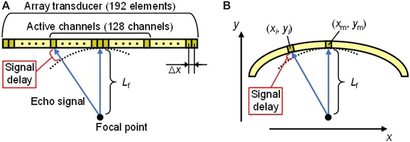
FIGURE 2. Dynamic focusing for reception with (A) conventional array transducer and (B) bent array transducer.
In the case of the bent array transducer as shown in Figure 2B, the delay time is different from Eq. 2 because the positions of the transducer elements change along the curved surface. Coordinates of the ith element and the center element of 128 active channels are defined as (xi, yi) and (xm, ym), respectively, in a two-dimensional plane. The delay time τi′ of the ith element for the proposed dynamic focusing is expressed as
Therefore, it is necessary to calculate the delay time from the curvature of the transducer approximated by a quadratic function using MRI. Coordinates of the ith element and the center element of 128 active channels are calculated from the quadratic function.
The signal processing for the generation of the ultrasonic B-mode image in the proposed method was as follows; 1) (xi, yi) and (xm, ym) were calculated from the curvature of the transducer approximated by a quadratic function using MRI; 2) the delay time τi′ of each element was calculated from Eq. 3; 3) the acquisition data of the ultrasonic echo signals were delayed by τi′, and then were summed; 4) a B-mode image was calculated with the logarithmic magnitude in a dynamic range of 60 dB. A B-mode image calculated with the conventional delay time τi was also prepared for comparison.
Results and Discussion
Magnetic Resonance Imaging of Bent Probe and Curvature Estimation
An MR image including the MR marker row of the ultrasonic probe is shown in Figure 3. Bending of the probe was observed from the arrangement of marker row. From the obtained MR images, two rows of marker positions in the MR one-dimensional space were detected, and the transducer coordinates were then calculated. Based on the coordinates, the curvature of the array transducer was approximated by a quadratic function in a two-dimensional plane. The estimated curvature of the array transducer was given by the following equation,
where x and y are coordinates in millimeters of B-mode image along lateral and range direction, respectively. The origin of Eq. 4 is at the vertex of the array transducer. The uncertainty of the quadratic function approximation for the coefficient in Eq. 4 was smaller than 0.1%. The difference between y in Eqs. 1,4 is less than 0.1 mm in |x| ≤ 44 mm. The array transducer was within this range. Equation 1 is a simple approximation of the parietal bone curvature for the phantom fabrication. However, the probe does not necessarily bend with the same curvature as the phantom. In addition, the actual curved surface of the parietal bone does not necessarily correspond to an elliptical surface. Therefore, we approximated the curvature of the array transducer with a quadratic function so that it can be applied to ordinary curved surfaces. Because of its small uncertainties, it is reasonable to approximate with a quadratic function at the place where the array transducer was arranged. Since the array transducer was bent in accordance with Eq. 4, (xi, yi) and (xm, ym) in Eq. 3 were calculated from Eq. 4.
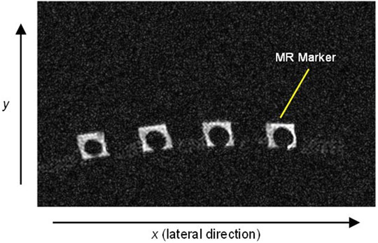
FIGURE 3. MR image of the cross section including the MR marker row of the ultrasonic probe that was obtained using 1.5 T MRI.
Verification of B-Mode Image Correction Using Dynamic Focusing in Reception for Bent Probe
The delay time τi′ was calculated based on Eqs. 3,4. Figures 4A,B shows B-mode images obtained using the proposed method with τi′ in Eq. 3 and the conventional method with τi in Eq. 2, respectively. In Figure 4B, it is evident that, due to the mismatch of the delay time, the reflector region was widened to the lateral direction compared to Figure 4A. To evaluate the resolution, the beam widths at −30 dB from the peak magnitude of each beam in the one-dimensional data, which is full width at half maximum, in the lateral direction were calculated. Table 3 shows the beam widths for three measurements of the ultrasonic echo signals. Each thread was defined as upper, middle, and lower thread in order of distance from the transducer. Comparing the results of each thread, the beam width of the proposed method was narrower than that of the conventional method in all cases. Especially for the upper thread set up near the ultrasonic transmission focus of 30 mm in the depth direction, the average beam width with the proposed method was 1.32 mm, which was close to the thread diameter of 0.98 mm. Ratios of the average beam width in the conventional method to that in the proposed method in each thread were also shown in Table 3. Although the beam widths increased with increasing the distance from the transmission focus in both methods, the ratio for the lower thread, which was about 20 mm away from the focus in the depth direction, was large. Therefore, there was a high improvement in the lateral direction by using the proposed method even in a region other than the transmission focal point. As a result, the B-mode image was corrected by calculating the delay time τi′ using the bending information. The phantom surface in this study was simulated the curvature of the human skull. The proposed beamforming is a good candidate for ultrasonic imaging through the curved surface. With the conventional non-flexible probe, it is difficult to attach it to an arbitrary curved surface. Therefore, a flexible acoustic coupler from the transducer to the head is needed [3]. On the other hand, with the flexible probe and the proposed beamforming technique, ultrasonic waves can be transmitted and received efficiently without the coupler. Further investigation with a head phantom mimicking bone and cerebral tissue is required for practical applications of the brain imaging through the skull.
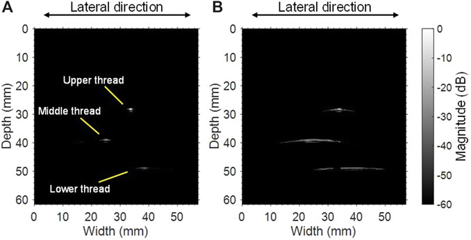
FIGURE 4. B-mode images of three nylon threads obtained using (A) the proposed method and (B) the conventional approach without curved surface information.
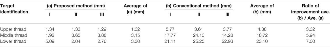
TABLE 3. Comparison of the beam widths at half maximum of each peak magnitude in the lateral direction in (a) the proposed method and (b) the conventional method of the dynamic focusing for reception, and improvement ratio of the spatial resolution of the images obtained by considering the estimated curved surface.
Conclusion
A B-mode image was corrected based on calculations of delay time in dynamic focusing for reception considering the bending of a flexible array probe equipped with MR-visible fiducial markers on a curved-surface phantom. The curvature of the bent probe was estimated using MRI. The delay time assigned to each transducer element in dynamic focusing for reception was calculated using the element coordinate obtained by the curvature. Ultrasonic echo signals from thread targets were observed with the bent probe, and then the B-mode image was modified using the delay time. As a result, it was confirmed that there was an improvement in the lateral direction in the B-mode image of the threads. Because the flexible probe can be fixed according to the shape of the skull, it is particularly effective for imaging of the brain. The proposed beamforming technique is expected to contribute to the improvement of the spatial resolution in the ultrasonic imaging with the flexible probe. Further experiments with a head phantom which also simulates skull-bone are needed to evaluate the clinical feasibility of our proposed method.
Data Availability Statement
The datasets generated for this study are available on request to the corresponding author.
Author Contributions
The authors of this manuscript meet all the criteria for authorship listed in the Frontiers author guidelines. KH contributed the synthesis of primary research articles. KN contributed to the technological elements of the text as well as made edits to the figures and tables. ST contributed sources within the field of dermatology for comparison within the text. IA is the principal investigator of this project and was involved in several steps of this project from idea generation to manuscript writing.
Funding
This study was supported in part by MEXT-Supported Program for the Strategic Research Foundation at Private Universities, 2013–2017.
Conflict of Interest
The authors declare that the research was conducted in the absence of any commercial or financial relationships that could be construed as a potential conflict of interest.
Acknowledgments
The authors thank to Ken Inagaki and Shimpei Arai for their experimental and programming supports to this study.
References
1. Adams S, Baum RP, Stuckensen T, Bitter K, Hӧr G. Prospective comparison of 18F-FDG PET with conventional imaging modalities (CT, MRI, US) in lymph node staging of head and neck cancer. Eur J Nucl Med (1998) 25:1255–60. doi:10.1007/s002590050293
2. Brinker ST, Preiswerk F, Mcdannold NJ, Parker KL, Mariano TY. Virtual brain projection for evaluating trans-skull behavior or transcranial ultrasound devices. Ultrasound Med Biol (2019) 45:1850–6. doi:10.1016/j.ultrasmedbio.2019.03.009
3. Ozennea V, Constansd C, Boura P, Santine DM, Valabreguee R, Ahninee H, et al. MRI monitoring of temperature and displacement for transcranial focus ultrasound applications. NeuroImage (2020) 204:116236. doi:10.1016/j.neuroimage.2019.116236
4. Bogdahn U, Becker G, Winkler J, Greiner K, Perez J, Meurers B, et al. Transcranial color-coded real-time sonography in adults. Stroke (1990) 21:1680–8. doi:10.1161/01.STR.21.12.1680
5. Inagaki K, Arai S, Namekawa K, Akiyama I. Sound velocity estimation and beamform correction by simultaneous multimodality imaging with ultrasound and magnetic resonance. Appl Sci (2018) 8:2133–43. doi:10.3390/app8112133
6. Chopra R, Curlel L, Hynynen K. Progress in multimodality imaging: truly simultaneous ultrasound and magnetic resonance imaging. IEEE Trans Med Imaging (2007) 26:1740–6. doi:10.1109/TMI.2007.903572
7. Lipsman N, Schwartz ML, Huang Y, Lee L, Sankar T, Chapman M, et al. MR-guided focused ultrasound thalamotomy for essential tremor: a proof-of-concept study. Lancet Neurol (2013) 12:462–8. doi:10.1016/S1474-4422(13)70048-6
8. Schlaier JR, Warnat J, Dorenbeck U, Proescholdt M, Schebesch K-M, Brawanski A. Image fusion of MR images and real-time ultrasonography: evaluation of fusion accuracy combining two commercial instruments, a neuronavigation system and a ultrasound system. Acta Neurochir (2004) 146:271–7. doi:10.1007/s00701-003-0155-6
9. Reynier C, Troccaz J, Fourneret P, Dusserre A, Gay-Jeune C, Descotes J-L, et al. MRI/TRUS data fusion for prostate brachytherapy. Preliminary results. Am Assoc Phys Med (2004) 31:1568–75. doi:10.1118/1.1739003
10. Tang AM, Kacher DF, Lam EY, Wong KK, Jolesz FA, Yang ES. Simultaneous ultrasound and MRI system for breast biopsy: compatibility assessment and demonstration in a dual modality phantom. IEEE Trans Med Imaging (2008) 27:247–54. doi:10.1109/TMI.2007.911000
11. Gururaja TR, Schulze WA, Cross LE, Newnham RE, Auld BA, Wang J. Resonant modes in piezoelectric PZT rod-polymer composite materials. Proc IEEE Ultrason Symp (1984) 523–7. doi:10.1109/ULTSYM.1984.198352
Keywords: skull surface compensation, ultrasonic dynamic focusing, flexible ultrasonic array, 1–3 composite piezoelectric materials, MRI marker
Citation: Hasegawa K, Namekawa K, Takayanagi S and Akiyama I (2021) Preliminary Investigation of Magnetic Resonance Imaging Guided Beamforming in Flexible Type Ultrasonic Array Transducers. Front. Phys. 9:522248. doi: 10.3389/fphy.2021.522248
Received: 21 December 2019; Accepted: 17 February 2021;
Published: 18 March 2021.
Edited by:
Nicola Toschi, University of Rome Tor Vergata, ItalyReviewed by:
Silvia Minosse, University of Rome Tor Vergata, ItalyMaurizio Marrale, University of Palermo, Italy
Copyright © 2021 Hasegawa, Namekawa, Takayanagi and Akiyama. This is an open-access article distributed under the terms of the Creative Commons Attribution License (CC BY). The use, distribution or reproduction in other forums is permitted, provided the original author(s) and the copyright owner(s) are credited and that the original publication in this journal is cited, in accordance with accepted academic practice. No use, distribution or reproduction is permitted which does not comply with these terms.
*Correspondence: Shinji Takayanagi, c3Rha2F5YW5AbWFpbC5kb3NoaXNoYS5hYy5qcA==