- Institute of Advanced Study in Science and Technology, Ministry of Science and technology, Guwahati, India
The effect of enhanced Landau damping on the evolution of ion acoustic Peregrine soliton in multicomponent plasma with negative ions has been investigated. The experiment is performed in a multidipole double plasma device. To enhance the ion Landau damping, the temperature of the ions is increased by applying a continuous sinusoidal signal of frequency close to the ion plasma frequency ∼1 MHz to the separation grid. The spatial damping rate of the ion acoustic wave is measured by interferometry. The damping rate of ion acoustic wave increases with the increase in voltage of the applied signal. At a higher damping rate, the Peregrine soliton ceases to show its characteristics leaving behind a continuous envelope.
Introduction
The Peregrine soliton is an isolated large-amplitude wave commonly known as rogue waves. These are extreme and rare wave events that usually appear on the ocean surfaces. It has two unique properties that distinguish the Peregrine soliton from ordinary solitons. Firstly, this large-amplitude wave is localized in both time and space axis; secondly, it has amplitude amplification of more than ∼3 times that of the background wave height. One generic mechanism considered responsible for the evolution of rogue waves is modulational instability. In this process, phase and amplitude modulation grow due to a delicate balance between nonlinearity and group velocity dispersion. Different solutions of nonlinear Schrodinger equation (NLSE) deal with such type of instability. In 1983, Peregrine derived a rational solution of NLSE in the context of water waves as a limit of a wide class of solutions to the NLSE [1]. This solution was later known as Peregrine soliton, which has been considered as a prototype of a rogue wave. Almost 3 decades later, the Peregrine soliton has been experimentally observed in various nonlinear mediums such as fiber optics, water, and plasma [2–4]. The NLSE, in its many forms, provides the solutions of extreme wave events (rogue waves, breathers, and envelope solitons) [5–7, 9]. Using the NLSE framework, the vigours properties of rogue waves have been theoretically studied in different plasma systems, such as electron-positron plasma [8], magnetized plasma [9], plasma with nonextensive electron velocity distribution [10], nonthermal plasma [11], and dusty plasma [12–16]. Recently, Tsai et al. [17] confirmed the presence of dust acoustic rogue waves in a self-excited laboratory dusty plasma medium. The existence of rogue waves has also been studied in a degenerate Thomas-Fermi plasma system [18]. The NLSE was derived for this purpose by considering cold inertial ions and Thomas-Fermi distributed electrons and positrons. Similar studies in electron-positron-ion plasma using a semirelativistic fluid model predicted the evolution of both bright and dark type envelope solitons [19, 20].
In multicomponent plasma with a critical concentration of negative ions, an initial amplitude-modulated ion wave packet undergoes self-modulation due to modulational instability and gives rise to the formation of bright and dark (hole) ion acoustic Peregrine soliton [4, 21]. The criteria for the generation of bright and hole Peregrine soliton out of an initial amplitude-modulated perturbation depend on the relative phase between the carrier and the envelope. The evolution of envelope-like solitons in such plasma is too described by the NLSE [22, 23]. The NLSE also supports the existence of higher-order and multiple Peregrine solitons [7, 24–26]. In our previous works, we have experimentally observed both second-order Peregrine soliton and multi-Peregrine soliton in multicomponent plasma containing negative ions [27, 28]. It was found that the characteristics of initial perturbations such as the amplitude (steepness) and modulation length (and depth) play a crucial role in the generation of both kinds of solitons.
Landau damping is a collisionless process because of which a longitudinal space charge wave (e.g., ion acoustic wave) in plasma decays exponentially with time. It occurs due to energy exchange between the waves and particles in plasma when their velocities are comparable. Eventually, Landau damping prevents the growth of instability and creates a region of stability in the parameter space. In laboratory discharge plasma with Maxwellian electrons, ion waves suffer Landau damping which become dominant when ion temperature is comparable to electron temperature (
The purpose of this paper is to report the experimental investigation of the Landau damping effect on Peregrine soliton in multicomponent plasma with a critical concentration of negative ions. The experimental setup and procedure to enhance the strength of Landau damping are discussed in Experimental Setup. The experimental measurement of Landau damping rate using interferometry and the observation of Peregrine soliton under enhanced damping are conferred in Results and Discussion. Finally, we present the concluding remarks in Conclusion.
Experimental Setup
Production of Multicomponent Plasma
The experiment is carried out in a DP device of a length of 120 cm and a diameter of 30 cm with a surface plasma confinement facility [21, 27]. The device consists of two magnetic cages separated by a floating mesh grid in between. Argon plasma is produced in both chambers at an operating pressure of
Method to Enhance the Strength of Landau Damping
In a DP device, the electron to ion temperature ratio is usually high (
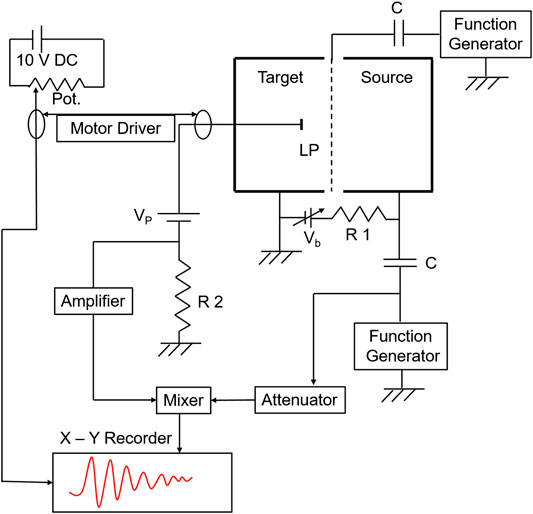
FIGURE 1. Block diagram of the experimental arrangement to enhance the Landau damping as well as measure the dispersion relation of ion acoustic waves.
Results and Discussion
Measurement of Landau Damping Rate of Ion Acoustic Wave
Experimentally, we first examine the linear dispersion relation of ion acoustic wave in the present argon plasma condition using interferometry. For this, continuous sinusoidal waves of frequency 100–800 kHz (100 kHz in step) with amplitude ≤200 mV are applied to the source anode from a function generator through a 1 μF capacitor. A reference signal from the function generator is applied to the balanced mixer’s right input through an attenuator. The plane Langmuir probe collects the signal continuously against the axial position with a motorized probe driving system. The probe is biased above the plasma potential in order to detect perturbations in electron saturation current. The signal is detected by the probe that is coupled to the left input of the mixer. The output of the mixer is fed to the Y axis of the X–Y recorder. The probe distance from the grid is calibrated using a separate voltage source with a potentiometer attached to the motor driving system and is connected to the X axis of the X–Y recorder. Figure 2 shows a typical linear dispersion relation for ion acoustic waves in a normal argon plasma. The solid line represents the theoretical dispersion relation, which is obtained by putting the experimental plasma parameters in Eq. 1. The theoretical relation (Eq. 1) is derived by considering the Maxwellian distribution having Te >> Ti [51].
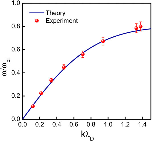
FIGURE 2. Dispersion relation of ion acoustic wave. The solid line is the theoretical curve calculated from Eq. 1.
Here
Usually, the Landau damping rate is calculated from the real (
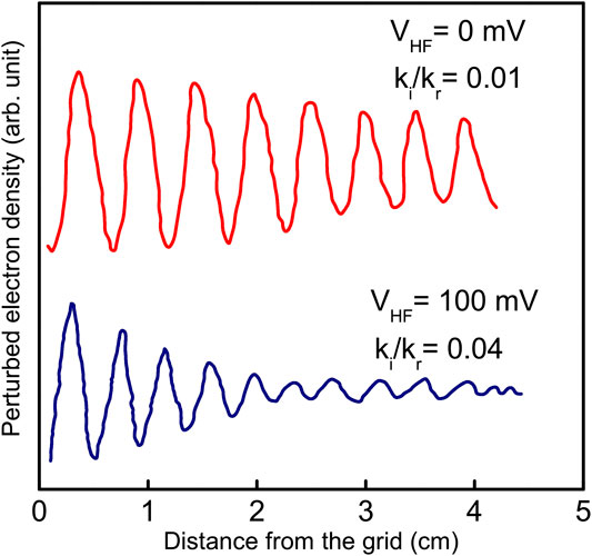
FIGURE 3. Typical interferometer pattern for a 500 kHz signal at VHF = 0 and 100 mV. The measured damping rates are also shown.
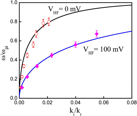
FIGURE 4. Normalized wavenumber
The damping rate of the ion acoustic wave increases as the amplitude of the rf signal is increased. In Figure 4, the solid lines are calculated for VHF = 0 and VHF = 100 mV from Eq. 2, whereas the open and closed symbols are calculated values of
Peregrine Soliton Under Enhanced Landau Damping
Initially, to excite the Peregrine soliton, an amplitude-modulated continuous sinusoidal wave of carrier frequency 380 kHz and modulation frequency 30 Hz is synthesized using a pair of function generators. The carrier frequency is typically selected at nearly half of the ion plasma frequency (fpi ∼ 892 kHz). The excitation amplitude of the carrier wave is varied from 2 to 9 V. Example of the evolution of Peregrine soliton at different initial amplitude is shown in Figure 5 at a fixed distance from the grid x = 9 cm. The initially applied signal is shown at the top. For carrier amplitude Vc = 5 V, the perturbation resembles the applied perturbation, which indicates linear wave propagation. The carrier amplitude is small, and the effective nonlinearity is just below the threshold, due to which the perturbation is linear. Gradually, with the increase in excitation amplitude, the wave packet suffers steepening due to nonlinearity. When the self-modulation of the wave packet reaches 100% at Vc = 8 V, the nonlinearity is entirely balanced by the group velocity dispersion, leading to the formation of Peregrine soliton. The amplitude amplification factor of the Peregrine soliton is found to be ∼3 (ratio of the peak amplitude of the wave packet to the background carrier wave amplitude). The group velocity of the perturbation is
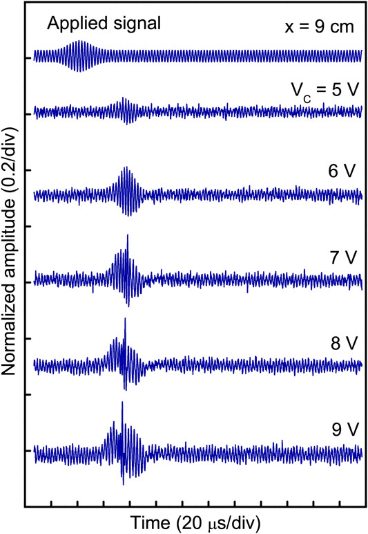
FIGURE 5. Typical examples experimentally observed Peregrine soliton at x = 9 cm from the grid. The top trace is the applied signal with carrier and modulation frequencies 380 and 30 kHz, respectively.
Next, a high-frequency rf signal is applied to the grid to enforce Landau damping on the evolution of Peregrine soliton while keeping the probe distance fixed at 9 cm (with Vc = 8 V). The frequency of the applied continuous signal is kept fixed at 900 kHz, which is in the range of ion plasma frequency. Modification of the Peregrine soliton due to the dissipative effect is shown in Figures 6A,B. At VHF = 0 mV, i.e., without the rf voltage, the Peregrine soliton is undisturbed. As VHF increases, the Peregrine soliton amplitude decreases, which signifies the enhancement of the strength of Landau damping. At VHF = 60 mV, the peak of the Peregrine soliton completely disappears. As indicated by the damping rate calculation, an increase in VHF provides strong Landau damping. As shown in Figures 6A,B, the amplitude of the Peregrine soliton decreases with an increase in VHF. Although the amplitude of the background carrier wave is increased at high VHF, which indicates the increase in ion temperature.
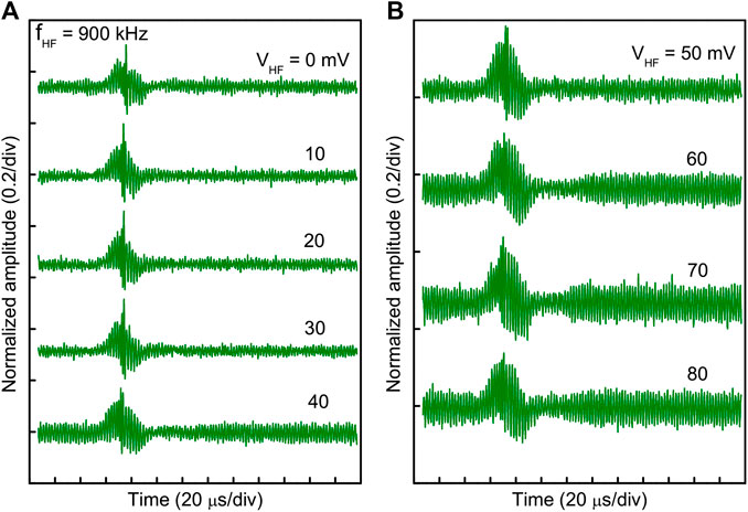
FIGURE 6. Observed oscilloscope trace at a fixed probe position 9 cm from the separation grid showing the transition of ion acoustic Peregrine soliton to an envelope with an increase in VHF. (A) For VHF = 0–40 mV. (B) For VHF = 50–80 mV.
A close observation of the evolution indicates that the solitary peak amplitude gradually decreases with the reduction of compression in the middle of the wave packet (due to which wave energy focuses on forming a soliton). An increase in ion temperature raises the number of resonant ions near the phase velocity of the wave, due to which Landau damping is enhanced, and the wave becomes less dispersive. As nonlinearity remains the same, now both dissipation (due to enhanced Landau damping) and dispersion compete to balance the nonlinearity.
Continuous Wavelet Transformation Analysis
The continuous wavelet transformation (CWT) analysis is performed for time-series data (presented in Figures 6A,B) and shown in Figures 7, 8. The time-series data are presented along with the CWT scalogram (3-dimensional surface plot of the absolute coefficient matrix) to clarify the temporal locations of the envelope. In Figure 7A, the CWT analysis of the Peregrine soliton for a temporal data length of 250 μs is shown (which corresponds to the top trace of Figure 6A). The CWT scalogram shows the broadening of the frequency spectrum at 75 µs, i.e., at the isolated peak location. For better resolution, CWT analysis is performed for a temporal length of 50–100 μs and shown in Figure 7B. A deep hole (dark blue) in front of the soliton peak is observed here. This hole represents the complete self-modulation of the initially applied wave packet due to modulational instability.
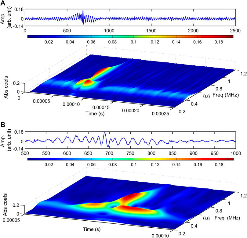
FIGURE 7. Typical CWT scalogram of fundamental Peregrine soliton without application of VHF. The probe position is at 9 cm. (A) Time series (top) and CWT scalogram (bottom) for Peregrine soliton for data length 0–250 µs. (B) Enlarged view of (A) for data length 50–100 µs.
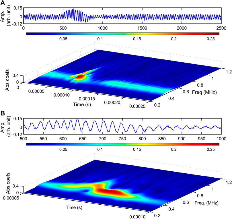
FIGURE 8. Typical CWT scalogram of fundamental Peregrine soliton with the application of VHF = 80 mV. The probe position is at 9 cm. (A) Time series (top) and CWT scalogram for data length 0–250 µs (bottom). (B) Enlarged view of (A) for data length 50–100 µs.
The CWT scalogram, along with the time-series data of envelope with enhanced Landau damping (with VHF = 80 mV), is shown in Figures 8A,B. Here, the reduction in the broadening of the frequency spectrum is clearly observed. Also, in Figure 8B, it is noticed that the deep hole in front of the largest wave crest almost disappears. Figure 7B shows the focusing of energy on the narrow wave group in the middle of the wave packet, whereas in Figure 8B, a continuous wave envelope is noticed. This signifies that wave energy focusing due to modulational instability vanishes because of the strong Landau damping (at VHF = 80 mV).
Conclusion
The evolution of ion acoustic Peregrine soliton under dissipation is observed in multicomponent plasma with negative ions. The strength of the Landau damping is increased by heating of ions via rf signal (close to the ion plasma frequency) application to the separation grid. The spatial damping rate of the ion acoustic wave is measured from the interferometer phase plot. The experimentally measured damping rate shows good agreement with the theory. The results show the modification of the evolution characteristics of Peregrine soliton. With high rf amplitude (VHF ≥ 60 mV), the soliton peak disappears, leaving behind an envelope only. At high VHF, the damping rate increases due to the rise in the thermal velocity of ions and thereby increasing resonant ions numbers close to the phase velocity of the wave. Once the dissipative effect becomes more substantial, the delicate balance between nonlinearity and group velocity dispersion gets affected, and the soliton disappears. However, a theoretical model considering the enhanced Landau damping effect is yet to be established and will be considered as a future study.
Data Availability Statement
The raw data supporting the conclusions of this article will be made available by the authors, without undue reservation.
Author Contributions
PP has done the experiment and data analysis as well as writing the manuscript.
Conflict of Interest
The author declares that the research was conducted in the absence of any commercial or financial relationships that could be construed as a potential conflict of interest.
Acknowledgments
The author would like to thank H. Bailung for his guidance throughout the experiment.
References
1. Peregrine D. Water waves, nonlinear Schrödinger equations and their solutions. J Aust Math Soc Ser B Appl Math (1983) 25:16–43. doi:10.1017/S0334270000003891
2. Kibler B, Fatome J, Finot C, Millot G, Dias F, Genty G, et al. The Peregrine soliton in nonlinear fibre optics. Nat Phys (2010) 6:790. doi:10.1038/nphys1740
3. Chabchoub A, Hoffmann NP, Akhmediev N. Rogue wave observation in a water wave tank. Phys Rev Lett (2011) 106:204502. doi:10.1103/PhysRevLett.106.204502 |
4. Bailung H, Sharma SK, Nakamura Y. Observation of Peregrine solitons in a multicomponent plasma with negative ions. Phys Rev Lett (2011) 107:255005. doi:10.1103/PhysRevLett.107.255005 |
5. Moslem WM, Shukla PK, Eliasson B. Surface plasma rogue waves. EPL (Europhysics Lett) (2011) 96:25002. doi:10.1209/0295-5075/96/25002
6. El-Tantawy SA, Wazwaz AM, Ali Shan S. On the nonlinear dynamics of breathers waves in electronegative plasmas with Maxwellian negative ions. Phys Plasmas (2017) 24:022105. doi:10.1063/1.4975090
7. Akbari-Moghanjoughi M. Electrostatic rogue-waves in relativistically degenerate plasmas. Phys Plasmas (2014) 21:102111. doi:10.1063/1.4897928
8. Moslem WM. Langmuir rogue waves in electron-positron plasmas. Phys Plasmas (2011) 18:10–4. doi:10.1063/1.3559486
9. Veldes GP, Borhanian J, McKerr M, Saxena V, Frantzeskakis DJ, Kourakis I. Electromagnetic rogue waves in beam–plasma interactions. J Optic (2013) 15:064003. doi:10.1088/2040-8978/15/6/064003
10. Moslem WM, Sabry R, El-Labany SK, Shukla PK. Dust-acoustic rogue waves in a nonextensive plasma. Phys Rev E - Stat Nonlinear Soft Matter Phys (2011) 84:066402. doi:10.1103/PhysRevE.84.066402
11. Wang Y, Li J, Dai C, Chen X, Zhang J. Solitary waves and rogue waves in a plasma with nonthermal electrons featuring Tsallis distribution. Phys Lett (2013) 377:2097–104. doi:10.1016/j.physleta.2013.06.008
12. Abdelsalam UM, Moslem WM, Khater AH, Shukla PK. Solitary and freak waves in a dusty plasma with negative ions. Phys Plasmas (2011) 18:092305. doi:10.1063/1.3633910
13. Chahal BS, Singh M, Shalini, Saini NS. Dust ion acoustic freak waves in a plasa with two temperature electrons featuring Tsallis distributio. Physica A (2018) 491:935–45. doi:10.1016/j.physa.2017.10.004
14. Shalini, Saini NS. Dust ion acoustic rogue waves in superthermal warm ion plasma. J Plasma Phys (2015) 81:905810316. doi:10.1017/S0022377815000082
15. Singh K, Kaur N, Saini NS. Head-on collision between two dust acoustic solitary waves and study of rogue waves in multicomponent dusty plasma. Phys Plasmas (2017) 24:063703. doi:10.1063/1.4984996
16., Saini NS, Kaur B, Singh M, Bains AS. Dust kinetic Alfvén solitary and rogue waves in a dusty plasma with two temperature n solitary and rogue waves in a dusty plasma with two Dust kinetic Alfv e temperature nonextensive ions. Phys Plasmas (2017) 24:073701. doi:10.1063/1.4989712
17. Tsai Y, Tsai J, Lin I. Generation of acoustic rogue waves in dusty plasmas through three-dimensional particle focusing by distorted waveforms. Nat Phys Lett (2016) 12:537–77. doi:10.1038/NPHYS3669
18. Ata-ur-Rahman . Electrostatic rogue waves in a degenerate Thomas-Fermi plasma. Braz J Phys (2019) 49:517–25. doi:10.1007/s13538-019-00676-3
19. Rahman A, Kerr MM, El-taibany WF, Kourakis I, Qamar A. Amplitude modulation of quantum-ion-acoustic wavepackets in electron-positron-ion plasmas : modulational instability, envelope modes, extreme waves. Phys Plasmas (2015) 22:022305. doi:10.1063/1.4907247
20. Kourakis I, Mc Kerr M, Ur-Rahman A. Semiclassical relativistic fluid theory for electrostatic envelope modes in dense electron-positron-ion plasmas: modulational instability and rogue waves. J Plasma Phys (2013) 79:1089–94. doi:10.1017/S0022377813001323
21. Sharma SK, Bailung H. Observation of hole Peregrine soliton in a multicomponent plasma with critical density of negative ions. J Geophys Res Sp Phys (2013) 118:919–24. doi:10.1002/jgra.50111
22. Bailung H, Nakamura Y. Observation of modulational instability in a multi-component plasma with negative ions. J Plasma Phys (1993) 50:231–42. doi:10.1017/S0022377800027033
23. Saito M, Watanabe S, Tanaca H. Modulational instability of ion wave in plasma with negative ion. J Phys Soc Japan (1984) 53:2304–10.
24. El-Tantawy SA, El-bedwehy NA, El-Labany SK. Ion-acoustic super rogue waves in ultracold neutral plasmas with nonthermal electrons Ion-acoustic super rogue waves in ultracold neutral plasmas with nonthermal electrons. Phys Plasmas (2013) 20:072102. doi:10.1063/1.4812630
25. El-Tantawy SA, Ali S, Maroof R, Wazwaz AM, El-Labany SK. On the super freak waves in multicomponent plasmas having two-negative ions: Xe+ − F− − SF6−and Ar+ − F− −SF6−plasmas. Indian J Phys (2017) 91:939–46. doi:10.1007/s12648-017-0982-6
26. El-Tantawy SA, El-Bedwehy NA, El-Labany SK. Ion-acoustic super rogue waves in ultracold neutral plasmas with nonthermal electrons. Phys Plasmas (2013) 20:072102. doi:10.1063/1.4812630
27. Pathak P, Sharma SK, Nakamura Y, Bailung H. Observation of second order ion acoustic Peregrine breather in multicomponent plasma with negative ions. Phys Plasmas (2016) 23:022107. doi:10.1063/1.4941968
28. Pathak P, Sharma SK, Nakamura Y, Bailung H. Observation of ion acoustic multi-Peregrine solitons in multicomponent plasma with negative ions. Phys Lett (2017) 381:4011–8. doi:10.1016/j.physleta.2017.10.046
29. McKenzie JF, Verheest F, Doyle TB, Hellberg MA. Compressive and rarefactive ion-acoustic solitons in bi-ion plasmas. Phys Plasmas (2017) 11:1762. doi:10.1063/1.1688332
30. Gill TS, Kaur H, Saini NS. Ion-acoustic solitons in a plasma consisting of positive and negative ions with nonisothermal electrons. Phys Plasmas (2003) 10:3927. doi:10.1063/1.1611486
31. Xue J. Head-on collision of dust-acoustic solitary waves. Phys Rev E - Stat Nonlinear Soft Matter Phys (2004) 69:016403. doi:10.1103/PhysRevE.69.016403
32. Sharma SK, Boruah A, Bailung H. Head-on collision of dust-acoustic solitons in a strongly coupled dusty plasma. Phys Rev E - Stat Nonlinear Soft Matter Phys (2014) 89:013110. doi:10.1103/PhysRevE.89.013110
33. Boruah A, Sharma SK, Nakamura Y, Bailung H. Observation of dust acoustic multi-solitons in a strongly coupled dusty plasma. Phys Plasmas (2016) 23:93704. doi:10.1063/1.4962566
34. Boruah A, Sharma SK, Bailung H, Nakamura Y. Oblique collision of dust acoustic solitons in a strongly coupled dusty plasma. Phys Plasmas (2015) 22:781035. doi:10.1063/1.4931735
35. Karpman VI, Shklyar DR. Nonlinear Landau damping in an inhomogeneous plasma. Sov Phys - JETP (1975) 40:53–6.
36. Ott E, Sudan RN. Nonlinear theory of ion acoustic waves with Landau damping. Phys Fluids (1969) 12:2388. doi:10.1063/1.1692358
37. VanDam JW, Taniuti T. Nonlinear ion acoustic waves with Landau Damping.pdf. J Phys Soc Japan (1973) 35:1973.
38. Mendonca JT, Bingham R. Plasmon beam instability and plasmon Landau damping of ion acoustic waves. Phys Plasmas (2002) 9:2604. doi:10.1063/1.1479142
39. Amendt P. Pseudomoment fluid modeling : electron Landau damping of ion-acoustic waves. Phys Plasmas (2001) 8:1437. doi:10.1063/1.1355681
40. Wong AY, Motley RW, D’Angelo N. Landau damping of ion acoustic waves in highly ionized plasmas. Phys Rev (1964) 133:A436. doi:10.1103/PhysRev.133.A436
41. Alexeff I, Jones WD, Montgomeryt D. Controlled Landau damping of ion acoustic waves. Phys Rev Lett (1967) 19:422–5.
42. Luo QZ, D’Angelo N, Merlino RL. Experimental study of shock formation in a dusty plasma. Phys Plasmas (1999) 6:3455. doi:10.1063/1.873605
43. Luo QZ, D’Angelo N, Merlino RL. Shock formation in a negative ion plasma. Phys Plasmas (1998) 5:2868–70. doi:10.1063/1.873007
44. Nakamura Y, Bailung H, Saitou Y. Observation of ion-acoustic shock waves undergoing Landau damping. Phys Plasmas (2004) 11:3925. doi:10.1063/1.1771654
45. Saitou Y, Nakamura Y. Ion-acoustic soliton-like waves undergoing Landau damping. Phys Lett (2005) 343:397–02. doi:10.1016/j.physleta.2005.06.035
46. Kozima H, Yamagiwa K, Tanaka T, Matsubara H, Yoshino H. Experimental study of an ion acoustic soliton with dissipation. J Phys Soc Japan (1989) 58:504–510.
49. Taylor RJ, Ikezi H, Mackenzie KR. A large double plasma device for plasma beam and wave studies A large double plasma device for plasma beam and wave studies. Rev Sci Instrum (1972) 43:1675. doi:10.1063/1.1685522
50. Nakamura Y, Ooyama M, Ogino T. Observation of spherical ion acoustic solitons. Phys Rev Lett (1980) 45:1565–69.
Keywords: peregrine soliton, landau damping, ion acoustic wave, multicomponent plasma, modulational instability
Citation: Pathak P (2021) Ion Acoustic Peregrine Soliton Under Enhanced Dissipation. Front. Phys. 8:603112. doi: 10.3389/fphy.2020.603112
Received: 05 September 2020; Accepted: 07 December 2020;
Published: 19 February 2021.
Edited by:
Amin Chabchoub, The University of Sydney, AustraliaReviewed by:
Nareshpal Singh Saini, Guru Nanak Dev University, IndiaAta ur Rahman, Islamia College University, Peshawar, Pakistan
Copyright © 2021 Pathak. This is an open-access article distributed under the terms of the Creative Commons Attribution License (CC BY). The use, distribution or reproduction in other forums is permitted, provided the original author(s) and the copyright owner(s) are credited and that the original publication in this journal is cited, in accordance with accepted academic practice. No use, distribution or reproduction is permitted which does not comply with these terms.
*Correspondence: Pallabi Pathak, cGFsbGFiaXBhdGhhazI3NkBnbWFpbC5jb20=
 Pallabi Pathak