 Junyun Zhang
 Zhuoling He
 Xu Yu
Xu Yu- School of Civil Engineering, Southwest Jiaotong University, Chengdu, China
With deep-buried depth, large span, high geo-stress, complex geological conditions, and its large sections, the deformation behavior of the Gaopo Tunnel is a complex three-dimensional problem. To reveal the deformation behavior of the tunnel and evaluate the current support scheme, this paper establishes a three-dimensional model by benching tunneling method, and compares the monitoring data to analyze the deformation behavior of the surrounding rock and the variation of the stress field in the support structure. The results demonstrate that the rock inclination angle is 4° to 10°, the micro-dip layered structure, which is the main factor for the asymmetric deformation behavior of soft rock tunnel with large section passing through coal seams. The maximum displacement of surrounding rock and the maximum stress of the supporting structure are within the safe range in current scheme. Furthermore, some measures are summarized, which may provide some reference for similar engineering in the future.
Introduction
Tunnels excavated in deep-buried and layered soft surrounding rock often encounter large deformation, accompanied by lining cracking and serious deformation of steel arch, such as Gushan Tunnel and Muzhailing Tunnel [1–3]. Unlike shallow tunnel, the deformation mechanism and stability of surrounding rock are difficult to control due to deep burial, high geo-stress, large span, and complex rock characteristics [4–10]. When excavating a tunnel in soft rock under squeezing stress, the ground slowly enters the opening without obvious cracks or loss of continuity. Continuous inward deformation of rock may occur due to the separation of rock debris or blocks from the excavated vault and wall [11]. Because of the damage of large deformation in the construction of soft rock tunnel, its deformation mechanism and control has attracted the attention of many scholars from the view of mechanics or geology for a long time [12–19].
With the development of computer technology, numerical simulation analysis of tunnel surrounding rock deformation is used widely. Especially after Mroueh and Shahrour [20] put forward the three-dimensional numerical simulation modeling and analysis, the numerical simulation has been recognized widely. Han et al. [21] used the step-by-step approaches modeling, combined with ANSYS, and carried out a full three-dimensional finite element analysis of the wall movement and damage caused by the excavation of the Hobart Tunnel. Liu et al. [22] used the monitoring data combined with ANSYS and FLAC3D to analyze the deformation behavior of the surrounding rock mass between the adit and the major tunnel of Wangdeng Tunnel.
In this paper, to reveal the large-deformation phenomena and evaluate the safety during tunneling in Gaopo Tunnel, comprehensive investigations have been undertaken by combining monitoring data and numerical simulation. The main reason of the large asymmetric deformation in Gaopo Tunnel is analyzed. And the feasibility of new support scheme is analyzed.
Site Details
Engineering Geology Condition
The large deformation section D3K342+750~D3K343+169 of Gaopo Tunnel is located at the southeast wing of Gaopo 1# anticline core.
The surrounding rock is mainly soft rock in the V class and the geological conditions are complex. The stratum at the construction site of the Gaopo Tunnel is mainly composed of sandstone, mudstone, carbonaceous shale, sandy mudstone, and coal seam. Located at the upper part of the formation, Longtan Group (P2l) has 5 to 31 coal seams, including 2 minable coal seams, with a total thickness of 120–180 m. P2l in the tunnel area contains poor coal quality, and pyrite nodule is well developed, and sulfur content is high. The vault and floor are mostly mudstone and bauxite mudstone, and the structure of coal seam is relatively simple.
Located in the fold belt of the East Yunnan Platform of Yangzi Quasi Platform in the north of Yungui Plateau, the geological structure of this tunnel is complex. The faults and folds are developed, mainly in the East-West structure, and the rock mass is broken. The representative occurrence of the corresponding proof stratum in this section is N40°-60°W/9°-12°SW. The route of the tunnel is about N46°W, approximately parallel to the stratum trend.
Geological exploration shows that surface water mainly consists of gully water and stream water. The rainfall is abundant. The branch gully is mostly seasonal running water. Replenished by atmospheric rainfall, the flow is greatly affected by seasonal changes, and the flow is discharged in the form of evaporation, infiltration, and runoff. Groundwater is mainly composed of pore water and bedrock fissure water. The pore water is localized in the partial gullies and the loose accumulation layer, and the bedrock fissure water exists and migrates in various structural surfaces of the bedrock and in the fault fracture zone. The two mainly receive atmospheric precipitation and surface water replenishment.
Geo-Stress Test
In this paper, the in-situ stress was measured by hydraulic fracturing method [23–26].
As shown in Table 1, within the depth range of geo-stress measurement, the maximum horizontal principal stress (σH) at the section was 14.37 MPa. The results indicated that the maximum principal stress and the minimum principal stress were both horizontal stresses and that only the second principal stress was in the vertical direction. The lateral pressure coefficient, the ratio of the σH and the vertical principal stress (σv), reached nearly 1.4. Generally, within the test depth of the tunnel, the minimum horizontal stress (σh) was the minimum principal stress, and the difference between the σv and σH was not significant. The effect of tectonic stress was not strong, and it was above the intermediate level. The directions of the maximum σH from shallow depth to deep depth were N50°W, N42°W, and N54°W respectively, indicating that the direction of the maximum principal stress near the measuring point was N49°W. The direction of route was about N46°W, and it was approximately parallel to the direction of the σH.
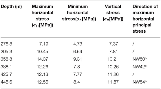
Table 1. Geo-stress test in the large deformation section at Gaopo Tunnel.
Deformation and Failure Characteristics
According to the in-site observation and monitoring data, the large deformation characteristics of coal seam section of Gaopo Tunnel are summarized as follows:
1) Large and uneven deformation. The main deformation in the tunnel was vault subsidence, floor heaven and sides shrinkage. And its development direction was perpendicular to the gentle dip direction of the stratum.
2) Large initial deformation and long-term deformation. The buried depth of the railway was 350–445 m, and the strength of the surrounding rock was low. The phenomena of floor heave, vault subsidence and side shrinkage lasted for a long period after 2018. Monitoring data indicated the deformation velocity of surrounding rock in this tunnel could reach 16 mm/d, and the deformation duration was usually 10 months.
3) Support failure. The Gaopo Tunnel was supported by original support scheme in December 2016. In January 2018, the whole tunnel was penetrated. Before the penetration, the surrounding rock was strengthened, and no obvious large deformations occurred. In March 2018, intense deformation and serious failure happened in the D3K34+750~D3K343+169 section of the main tunnel and the corresponding adit. The deformation sign of the initial support and lining is shown in Figures 1, 2. The maximum deformation of side near the main tunnel was about 1 m. The longitudinal influence range was wide. There were long longitudinal cracks on the vault and floor of main tunnel, and the longitudinal crack on the filling surface of floor was up to 50 mm (Figure 3).
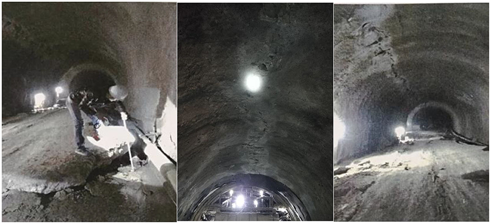
Figure 1. Initial support failure.
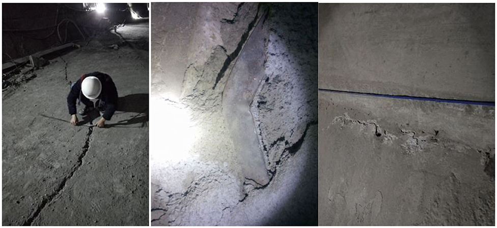
Figure 2. Deformation of major tunnel lining.
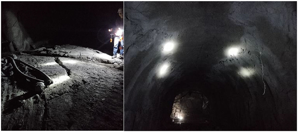
Figure 3. Deformation sign of support.
Original Support Scheme and Current Support Scheme
Original Support Scheme
Gaopo Tunnel was constructed by scheme of “two cross passageways, main and auxiliary inclined shaft and one ventilation shaft.” The horseshoe excavation section of the main tunnel reached 155 m2, belonging to super-large section tunnel. The original support scheme of deformation section was determined by relevant mechanical tests in the test section and the geological conditions. In the design scheme, the floor is removed, and inverted arch with I-shaped steel is added. And the support scheme for the main tunnel is:
1) Severely deformed section: Increase the curvature of the inverted arch, and deepen the center of the inverted arch by 50 cm. Add anchors to the inverted arch, and increase the reserved deformation by 30 cm. Reinforced concrete is used for the initial support, and type III composite lining is used for the secondary lining. The support parameters are shown in Table 2 and the section structure parameters are shown in Figure 4A.
2) Moderately large deformation section: The reserved deformation is 25 cm, and the initial support is reinforced with full-ring I20b steel. The secondary lining is reinforced concrete, type A composite lining. The supporting parameters are specified in Table 3.
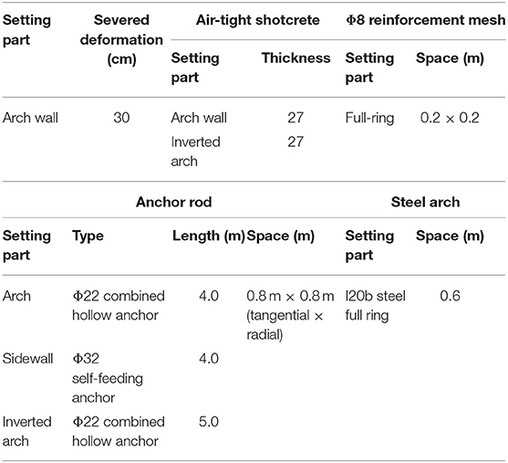
Table 2. Parameters of type III composite lining.
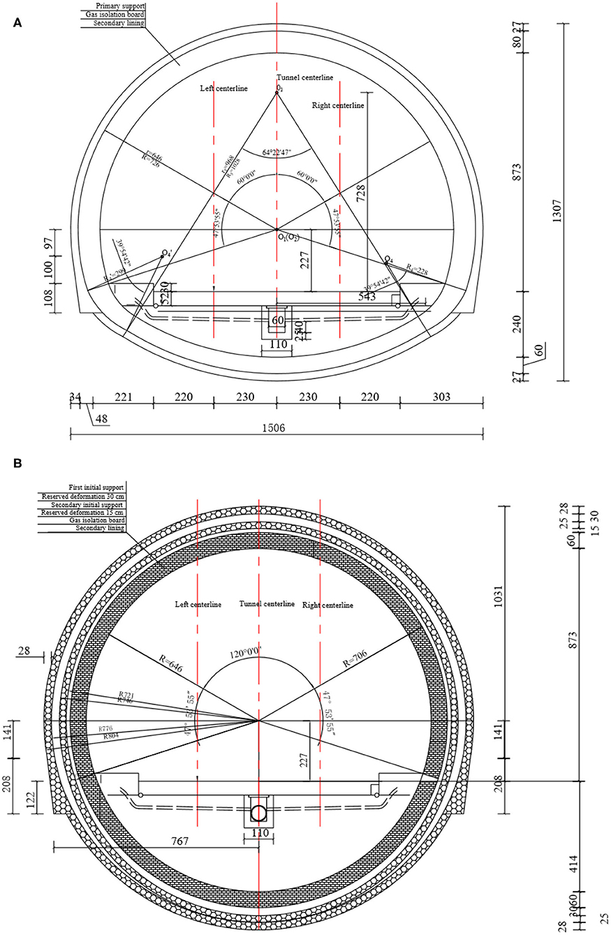
Figure 4. Section structure parameters: (A) Type III composite lining section. (B) Type IV composite lining.
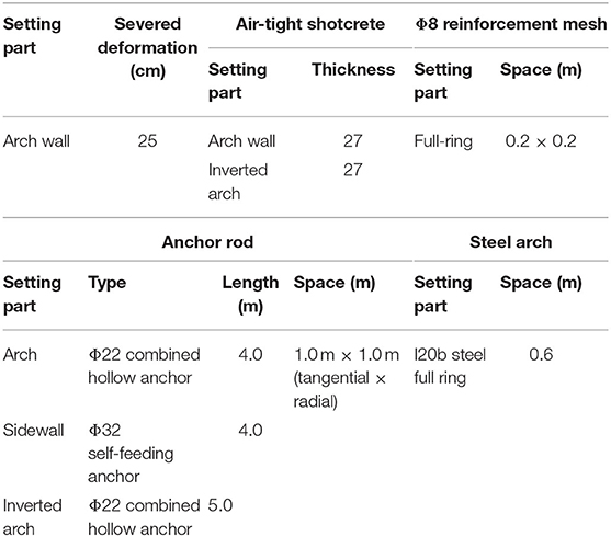
Table 3. Parameters of type A composite lining.
Current Support Scheme
The Gaopo Tunnel is a deep-buried tunnel, and the buried depth is more than 400 m. The excavation section is large, the horseshoe section is nearly 155 m2. It was difficult to achieve sufficient accuracy in the preliminary geological survey. Although the original support scheme of the section D3K342+750~D3K343+169 was determined by the mechanical test in the test section, the influence of the core part of the Gaopo 1# anticline was not fully considering. From the deformation of the supporting structure, the structural stiffness of the type III composite lining was still insufficient, and the length of the anchor rod was not enough. And the radius of the loose circle of the surrounding rock was large. Therefore, type IV composite lining was adopted. Specific engineering measures are as follows:
1) Grouting with aperture of 50 mm is adopted for the range of arch wall in deformed section, with 5 m length per hole and 1.2 × 1.2 m (tangential × radial) spacing to improve surrounding rock conditions at arch wall.
2) Removal and expansion of original support structure are carried out in turn with trolley, with the length of each expansion about 6–10 m. The previous horseshoe section is expanded to circle section. Open-fire operation is forbidden in the whole process. Tunnel ventilation is strengthened to ensure that gas concentration in air flow is not more than 0.4%.
3) New support structure consists of two layers of initial support and one layer of secondary lining with design thickness. HW200 I-steel is used for the first layer of initial support steel arch, and HW175 I-steel is used for the second layer of initial support steel arch. The spacing of the steel arch is 0.6 m. The construction time of the secondary initial support depends on the deformation of the surrounding rock and monitoring data after the first initial support is installed. The secondary lining should be installed after the surrounding rock is basically stable after the construction of primary support.
4) Anchors with 12 and 10 m long are designed to strengthen the whole ring in the tunnel arch wall and the inverted arch. The actual length of anchor rod during construction is optimized according to the monitoring data of test section and actual construction situation in site, and reinforced concrete is applied in the full ring.
5) The form of tunnel track depends on the field deformation and monitoring data at later stage, and ballasted track is recommended. Specific parameters of type IV composite lining of Gaopo Tunnel are shown in Table 4 and structural parameters of section are shown in Figure 4B.
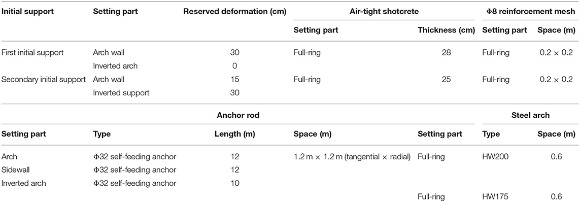
Table 4. Parameters of type IV composite lining.
Three-Dimensional Numerical Analysis
Model and Material Parameters
In this paper, the geometric dimension of the model is defined as width X × Y × Z = 170 m × 170 m × 50 m. The model is defined as three parts: upper, middle and lower parts, corresponding to the general stratum, coal seam and general stratum respectively, as shown in Figure 5. The coal seam is the surrounding rock of inclined layered coal measure stratum that the tunnel passes through, and the dip angle of stratum is set as 9°.
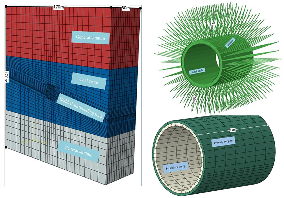
Figure 5. The numerical model and the element mesh.
According to the new support scheme, the maximum excavation span of circular tunnel section is 16.08 m. To simplify the calculation, the influence of the reserved deformation is not considered in the support structure. The reinforcement, steel mesh and shotcrete in the two layers of initial support are simplified as one layer of support, and the thickness of initial support is 53 cm, regarded as solid element, and its material parameters are determined according to the weight ratio of each component. The diameter of anchor is 32 mm, realized by wire element. The steel arch frame is HW200 I-beam steel, realized by wire element. Both of them bear the load by embedding into the soil. The length of arch wall is 12 m, and the range of inverted arch is 10 m, realized by solid element. The thickness of secondary lining is 60 cm, ignoring the existence of reinforcement, regarded as solid element. After the model assembly, there are 25,433 units and 27,635 nodes in total. C3D8R (8-node linear brick, reduced integration with hourglass control) element was used for surrounding rock simulation.
In the design model, the horizontal direction of displacement is fixed in X direction. The bottom surface is fixed in X direction, Y direction and Z direction. The excavation direction is fixed by Z direction, and the top is free.
The Drucker-Prager model is adopted in this numerical analysis, and the required parameters are sorted out as Table 5 according to the geological exploration data.
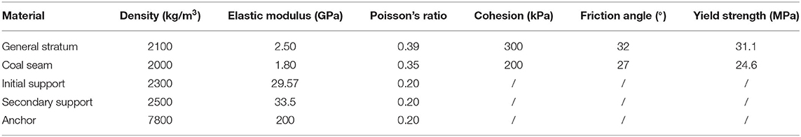
Table 5. Physical-mechanical properties of the material at site.
Numerical Model Establishment
In the process of numerical simulation, 19 construction steps are set to simulate the support process of tunnel excavation. In the field, the support is excavated by benching tunneling method. The length of each excavation step is set at 3 m and excavation is set at 7 steps, which are divided into two steps. The initial support is lagged behind one construction step of excavation and the lining is lagged behind four construction steps of excavation. And keyword “Model Change” is used to rock mass excavation and support structure installment. Load conditions are as follows:
1. Calculation of initial geo-stress field.
2) Balance of geo-stress.
3) First step excavation of upper bench.
4) Second step excavation of upper bench and initial support installation of the previous step.
5) Excavation of upper bench to 12 m, installment of initial support to 9 m and installment of the first step lining, and start of excavation of lower bench.
6) Excavation of upper bench to 15 m, excavation of lower bench to 6 m, and installment of initial support to the lower bench of 3 m. The second step lining installment and start of the third excavation of the lower bench.
7) In turn, analogy is carried out until the scheduled excavation of surrounding rock and support structure are installed.
Typical working conditions of 3-D numerical simulation of Gaopo Tunnel are shown as Figures 6–8.
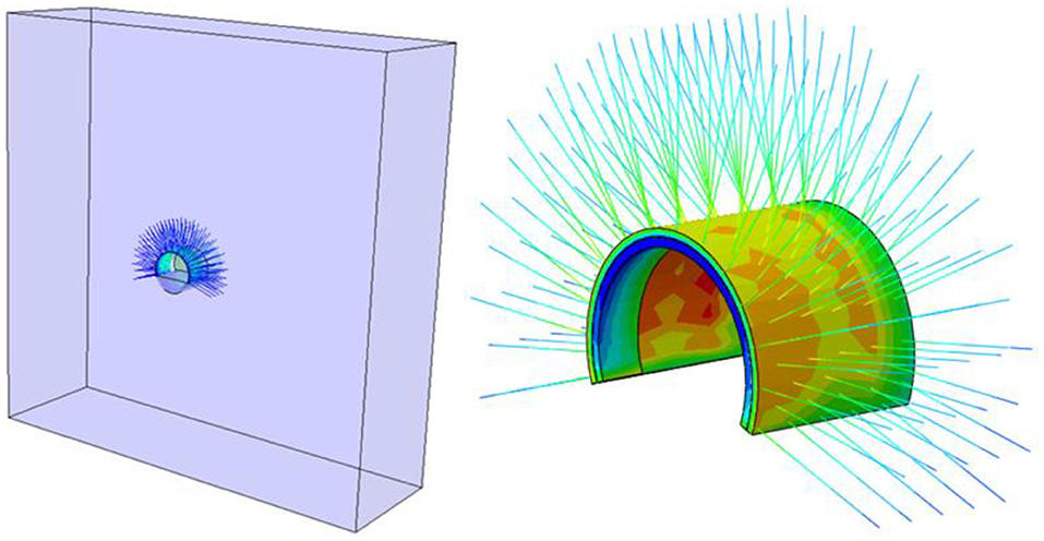
Figure 6. The fifth construction step: excavation up to 12 m, initial support construction up to 9 m, and lining installation.
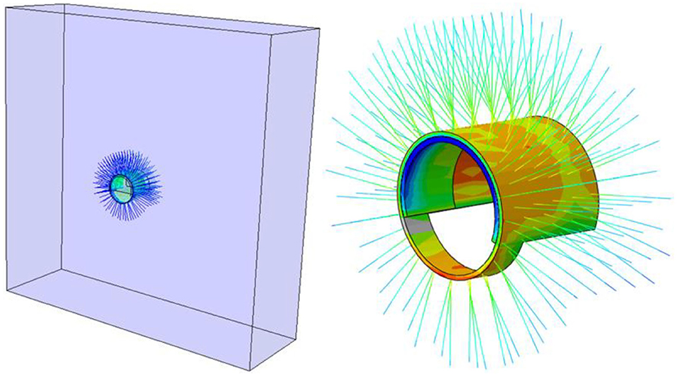
Figure 7. The sixth construction step: excavation up to 15 m, excavation down to 6 m, and initial support down to the lining.
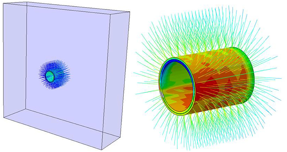
Figure 8. The seventh construction step: the planned surrounding rock excavation completion and support structure construction.
Results
Based on the in-site monitoring data of D3K342+940 section of Gaopo Tunnel, the simulation results are compared with the corresponding monitoring data to discuss the deformation of surrounding rock and stress of support structure in Gaopo Tunnel. The main items for comparison and analysis are surrounding rock deformation, initial support stress, steel arch stress, anchor axial force and secondary lining reinforcement stress. According to the ABAQUS stress symbol, the compression is negative and the tension is positive.
It should be pointed out, that, due to construction and other reasons, part of the anchor hole grouting is not compact, which cannot ensure that the monitoring data can perfectly reflect the tension stress of the anchor rod. And other measuring points cause data distortion due to component wire breakage caused by construction.
Displacement Analysis
After the tunnel excavation and support structure installment by benching tunneling method, the nephogram of horizontal and vertical displacements of surrounding rocks is shown in Figure 9. Vault subsidence, inverted arch floor heaven, left or right sidewall convergences corresponding joints of target section are extracted, and the displacements with the construction steps are shown in Figure 10. The displacements of the section D3K342+940 are shown in Figure 11.
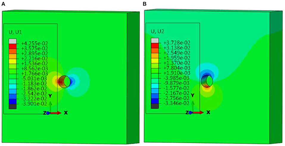
Figure 9. Displacement nebulogram after excavation and support: (A) Horizontal displacement after stabilization (B) Vertical displacement after stabilization (Unit: m).
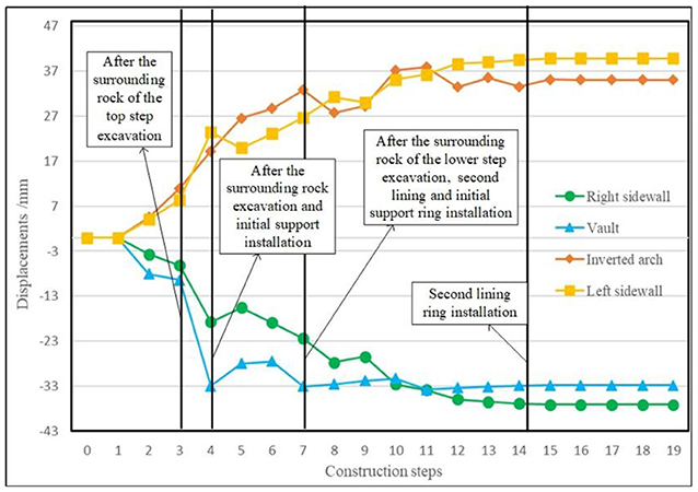
Figure 10. Curves of displacements and construction steps of surrounding rock.
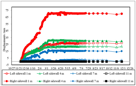
Figure 11. Displacements curves of the monitoring section D3K342+940.
From Figures 9, 11, the overall deformation of surrounding rock after tunnel stabilization is in centimeter level, consistent with the magnitude of monitoring data. The horizontal convergence of surrounding rock is slightly larger than the vertical displacement, which is consistent with the law that the horizontal stress is greater than the vertical stress in field stress test. In addition, in the horizontal displacement, the convergence value of the left is larger than that of the right.
From Figure 10, the deformation of surrounding rock presents a “S” shape with tunnel excavation. Before the tunnel face reaches the target section, vault subsidence, inverted arch floor heaven, left or right sidewall convergences are 9.43, 10.97, 8.44, and 6.13 cm, accounting for 28.7, 31.2, 21.2, and 16.5% of the total amount, respectively. After the tunnel face reaches the target section, vault subsidence, floor heaven, left or right sidewall convergence are 32.68, 19.19, 23.47, and 18.7 cm, respectively. They account for 99.4, 54.8, 58.9, and 50.4% of the total amount, respectively. With the continuous advancement of the tunnel face and the disturbance near the target section of the construction team, the deformation of surrounding rock is further expanded. After that, with the construction of initial support and lining on the target section, the deformation of surrounding rock on the target surface is restrained and finally tends to stabilize.
Stress Analysis
The stress nephogram after stabilization is shown in Figure 12. And the in-site monitoring data is shown in Figure 13. Because of the difficulty of construction in site, in the large deformation test section of Gaopo Tunnel, only anchor element, embedded at sidewalls and inverted arch, is measured the axial force of anchor rods. Therefore, only the tensile stress of sidewalls and joint at inverted arch is extracted.
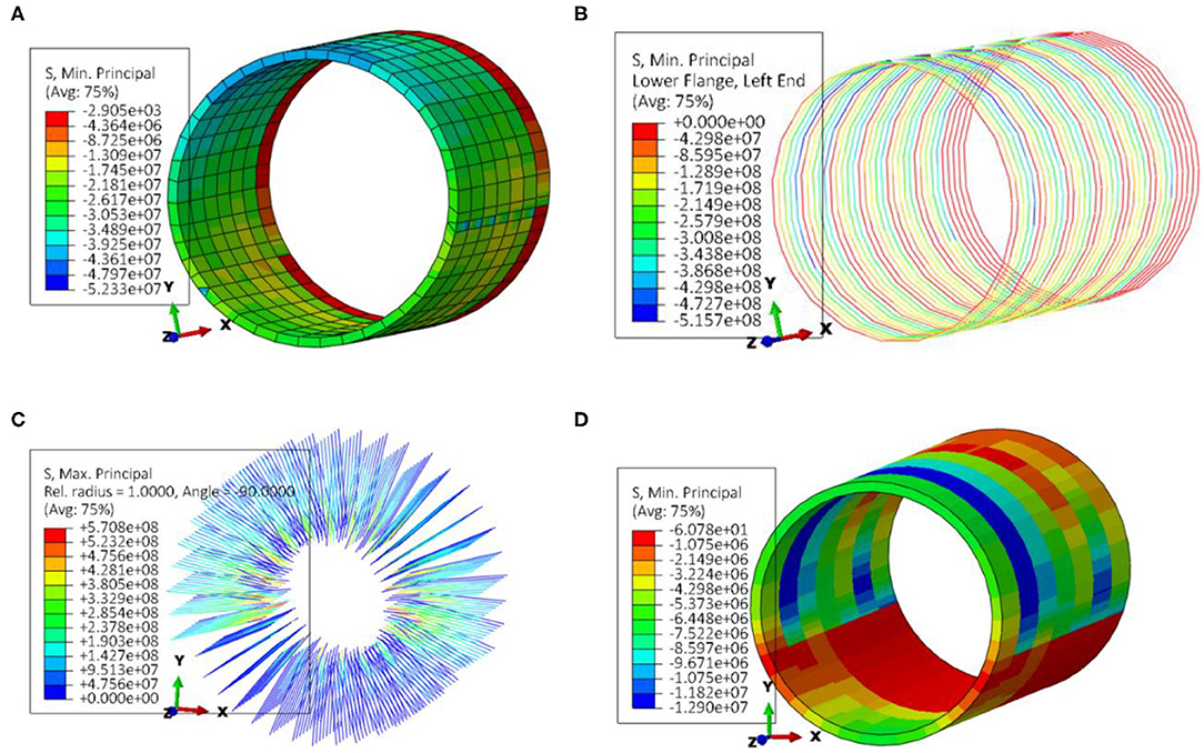
Figure 12. Simulated results: (A) Initial support (B) Steel arch (C) Anchor rod (D) Secondary lining (Unit: Pa).
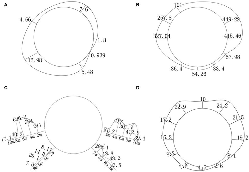
Figure 13. Monitoring data diagram: (A) Initial support (B) Steel arch (C) Anchor rod (D) Secondary lining (Unit: MPa).
In Figure 12, the compressive stress in initial support mainly concentrates on about 23 MPa, with the maximum value of 52.3 MPa. The compressive stress in steel arch mainly concentrates on between 200 and 450 MPa. The maximum tensile stress in anchor is 570 MPa. Within the limit tensile strength of the anchor, the tensile stress groups are mainly located near the clearance part of the anchor. The tensile stress of anchor rod gradually decreases with the extension of deep-buried surrounding rock, and the variation is consistent with monitoring data.
From Figures 12, 13, the compression stress of arch wall is greater than that of inverted arch. The maximum compressive stress is concentrated in the right part. The tensile stress of anchor rod at sidewalls is much higher than that at inverted arch, and the value of tension stress of anchor rod is not different from that of monitoring significantly. In addition, the tension stress of anchor rod at left side and left elevation arch is higher than that at right side and right elevation arch, which agrees with monitoring data.
The compressive stress of secondary lining in numerical simulation is generally smaller than that of in-site monitoring data. This is because the in-site monitoring value is the compressive stress of secondary lining force on steel bar, and the joint fissures are developed in large deformation section of Gaopo Tunnel, which is affected by Gaopo1# anticline core. The surrounding rock is mainly soft rock, such as argillaceous sandstone. In addition, during the excavation of the tunnel, plastic deformation is not considered in numerical simulation, for simplifying calculation.
In general, the compressive stress of the secondary lining steel bar monitored in site or analyzed by numerical simulation is small, about 10–25 MPa, only 7.4% of the compressive strength of the steel bar. Therefore, under the current support scheme, the secondary lining bears less compressive stress in fact. It is more to deal with the plastic deformation of surrounding rock softening after tunnel operation, and it exists as a safety reserve.
Gaopo Tunnel Deformation Control Technology
Considering that surrounding rock of this deformation section is coal seam, the risk of gas leakage existences if reinforcement is carried out based on original support structure. In order to control large deformation of tunnel, the original support structure of the deformation section is determined to be removed and a new support scheme is implemented. Now the engineering measures for large deformation treatment of Gaopo Tunnel are introduced as follows, which may provide some reference for similar projects in the future.
Increase Support Structure Stiffness
Compared with the original support scheme with one layer of initial support, the new support scheme uses two layers of initial support. In the new support scheme, the thickness of shotcrete has been increased from 27 to 53 cm, the type of steel arch has changed from I20b to HW200 with higher strength and two-layer support. And the anchor has changed from Φ22 combined hollow anchor to Φ32 self-feeding anchor, and the length has increased from 4 m to 12 m.
Improve Tunnel Section Shape
In order to make full use of the potential of support structure and reduce stress concentration, the horseshoe tunnel section is changed to a circular section. The circular section can make the stress distribution of support structure more uniform and it is more convenient to the construction of two-layer steel arch. After the support structure is installed, the circular section is beneficial to the slow geo-stress release.
Layered Support to Control Deformation
In order to reduce the disturbance to surrounding rock, flexible supporting structure is often used. After fully releasing the stress of surrounding rock, the rigid support is used to support in time. So that the surrounding rock and the supporting structure form a whole and bear the stress together. The new support scheme of Gaopo Tunnel adopts two-layer primary support. After the deformation of the first layer of initial support is stable, the second layer of primary support is installed in time. After the deformation of the initial support tends to be stable, the secondary lining should be installed in time. With enough reserved deformation, the stress of surrounding rock can be fully released, and then flexible supporting structure is applied to make the surrounding rock and supporting structure reach a new equilibrium.
Intensify Inverted Arch and Restrain Uplift
In the large deformation section of Gaopo Tunnel, the stress of support is asymmetric, and the stress of the upper structure is generally greater than that of the lower structure. Therefore, the inverted arch is expanded into a circle, and two layers of initial support and two layers of steel arch are carried. In addition, 10 m long Φ32 self-feeding anchor rod is installed. Therefore, the support strength at the bottom of the tunnel is sufficient.
Conclusion
The tunnel is a typical coal seam tunnel with deep-buried depth, large section. Based on monitoring data and numerical simulation, the deformation behavior is analyzed. Some measures have been taken to restrain the large deformation. The main conclusions are as follows:
1) Softening expansion exists in surrounding rocks. The surrounding rock in the deformation section is mainly composed of mudstone and carbonaceous shale, which has weak expansion, even medium expansion in partial region. The site revealed that linear and strand-shaped groundwater flowed near the tunnel. Inadequate management, coupled with the release of stress after the tunnel construction, the rock fissures gradually expanded, and a favorable water channel was formed, causing the surrounding rock softened, which increased the stress on the supporting structure, resulting its deformation.
2) The surrounding rocks are mainly weak weathered mudstone, carbon shale with sandy mudstone, etc. Soft and hard rocks alternate each other, and the rock mass is relatively fractured. The dip angle of stratum is 4°-10° and it belongs to gentle dip layered structure. The deformation of surrounding rock and support stress are controlled by the layered structure with gentle dip obviously. Horizontal convergence of surrounding rocks is slightly larger than vertical displacement, in addition, convergence value of left sidewall is larger than right sidewall in horizontal displacement. Compressive stress of arch wall is greater than that of inverted arch floor, and overall compressive stress of right part of steel arch is greater than that of left part. Tensile stress of anchor rod at sidewall is much greater than that at inverted arch floor, and tensile stress of anchor rod at left sidewall and left inverted arch floor is greater than that at the right.
3) After the installment of the support structure, the maximum displacement of surrounding rock and the maximum stress of the supporting structure are within the safe range. And their changes during the tunnel excavation are basically stable after the completion of the secondary lining construction. The stress of the secondary lining is similar to the field monitoring data, and the overall stress is very small. The secondary lining is mainly used to resist the surrounding rock plastic deformation after the tunnel operation, which is the same as the idea of NATM. In the process of tunnel excavation, the broken-rock pressure and deformation pressure of surrounding rock are mainly produced by surrounding rock and initial support. Compared with field monitoring data, it can be concluded that Gaopo Tunnel is safe under the current support scheme.
4) The engineering treatment measures for large deformation section of Gaopo Tunnel are analyzed and summarized, including increasing support structure stiffness, improving tunnel section shape, deformation controlling by layered support, and strengthening inverted arch and restraining uplift.
Data Availability Statement
All datasets generated for this study are included in the article/supplementary material.
Author Contributions
JZ conceived and designed the research and contributed to funding supports. XY performed the data monitoring. XY and ZH analyzed the data. XY wrote the manuscript. ZH revised the English language of the manuscript.
Funding
This research was supported by the National Nature Science Foundation of China (Grant No. 51678494).
Conflict of Interest
The authors declare that the research was conducted in the absence of any commercial or financial relationships that could be construed as a potential conflict of interest.
Acknowledgments
This work was also carried out under the tunnel engineering research and development project of the Southwest Jiaotong University. We appreciate any institutions and individuals that have provided support for this paper.
References
1. Gioda G, Cividini A. Numerical methods for the analysis of tunnel performance in squeezing rocks. Rock Mech Rock Eng. (1996) 29:4. doi: 10.1007/BF01042531
2. Li SC, Hu C, Li LP, Song SG, Zhou Y, Shi SS. Bidirectional construction process mechanics for tunnels in dipping layered formation. Tunnel Underground Space Technol. (2013) 36:57–65. doi: 10.1016/j.tust.2013.01.009
3. Yang SQ, Chen M, Jing HW, Chen KF, Meng B. A case study on large deformation failure mechanism of deep soft rock roadway in Xi'an coal mine, China. Engineer Geol. (2017) 217:89–101. doi: 10.1016/j.enggeo.2016.12.012
4. Barla G, Bonini M, Semeraro M. Analysis of the behaviour of a yield-control support system in squeezing rock. Tunn Undergr Space Technol. (2011) 26:146–54. doi: 10.1016/j.tust.2010.08.001
5. Cao CY, Shi CH, Lei MF, Yang W, Liu J, et al. Squeezing failure of tunnels: a case study. Tunn Undergr Space Technol. (2018) 77:188–203. doi: 10.1016/j.tust.2018.04.007
6. Schubert W. Dealing with squeezing conditions in alpine tunnels. Rock Mech Rock Eng. (1996) 29:145–53. doi: 10.1007/BF01032651
7. Xu F, Li SC, Zhang QQ, Li L, Shi S, Zhang Q. A new type support structure introduction and its contrast study with traditional support structure used in tunnel construction. Tunn Undergr Space Technol. (2017) 63:171–82. doi: 10.1016/j.tust.2016.11.012
8. Indraratna B, Haque A, Aziz N. Shear behavior of idealized filled joints under constant normal stiffness. Geotechnique. (1999) 49:331–55. doi: 10.1680/geot.1999.49.3.331
9. Indraratna B, Jayanathan M, Brown ET. Shear strength model for over consolidated clay-filled idealised rock joints. Geotechnique. (2008) 58:55–65. doi: 10.1680/geot.2008.58.1.55
10. Indraratna B, Oliveira DAF, Brown ET. A shear-displacement criterion for soil-filled rock discontinuities. Geotechnique. (2010) 60:623–33. doi: 10.1680/geot.8.P.094
11. Bian K, Liu J, Liu ZP, Liu SG, Ai F, Zheng XQ, et al. Mechanisms of large deformation in soft rock tunnels: A case study of Huangjiazhai Tunnel. Bull Eng Geol Environ. (2019) 78:431–44. doi: 10.1007/s10064-017-1155-8
12. Brox D, Hagedorn H. Extreme deformation and damage during the construction of large tunnels. Tunn Undergr Space Technol. (1999) 14:23–8. doi: 10.1016/S0886-7798(99)00010-3
13. Dalgic S. Tunneling in squeezing rock, the Bolu tunnel, Anatolian motorway, Turkey. Eng Geol. (2002) 67:73–96. doi: 10.1016/S0013-7952(02)00146-1
14. Bizjak KF, Petkovsek B. Displacement analysis of tunnel support in soft rock around a shallow highway tunnel at Golovec. Eng Geol. (2004) 75:89–106. doi: 10.1016/j.enggeo.2004.05.003
15. Zhou X, Qian Q. Zonal fracturing mechanism in deep tunnel. Chin J Rock Mech Eng. (2007) 26:877–85. doi: 10.1016/S1872-2067(07)60020-5
16. Khanlari G, Meybodi RG, Mokhtari E. Engineering geological study of the second part of water supply Karaj to Tehran tunnel with emphasis on squeezing problems. Engineer Geol. (2012) 145–146:9–17. doi: 10.1016/j.enggeo.2012.06.001
17. Wang MY, Zhang N, Li J, Ma LJ, Fan PX. Computational method of large deformation and its application in deep mining tunnel. Tunn Undergr Space Technol. (2015) 50:47–53. doi: 10.1016/j.tust.2015.06.006
18. Shou YD, Zhou XP, Qian QH. A critical condition of the zonal disintegration in deep rock masses: Strain energy density approach. Theoret Appl Fract Mech. (2018) 97:322–32. doi: 10.1016/j.tafmec.2017.05.024
19. Kalamaris GS, Bieniawski ZT. A rock mass strength concept for coal incorporating the effect of time. In: Proceedings of the Eighth International Congress on Rock Mechanics. Rotterdam: Balkema. (1995). p. 295–302.
20. Mroueh H, Shahrour I. A full 3-D finite element analysis of tunneling–adjacent structures interaction. Comput Geotech. (2003) 30:245–53. doi: 10.1016/s0266-352x(02)00047-2
21. Han HY, Liu HY, Chan A, Mcmanus T. Three-dimensional finite element modelling of excavation-induced tunnel wall movement and damage: a case study. Sādhanā. (2019) 44:185. doi: 10.1007/s12046-019-1167-0
22. Liu H-L, Li S-C, Li L-P, Zhang QQ. Study on deformation behavior at intersection of adit and major tunnel in railway. J Civil Engin. (2017) 21:2459–66. doi: 10.1007/s12205-017-2128-y
23. Matsunaga I, Kuriyagawa M, Sasaki S. In situ stress measurements by the hydraulic fracturing method at Imaichi pumped storage power plant, Tochigi, Japan. Int J Rock Mech Min Sci Geomech Abstr. (1989) 26:203–9. doi: 10.1016/0148-9062(89)91970-0
24. Hayashi K, Ito T. In situ stress measurement by hydraulic fracturing at the Kamaishimine. In t J Rock Mech Min Sci Geomech Abstr. (1993) 30:951–7. doi: 10.1016/0148-9062(93)90051-E
25. Haimson BC, Cornet FH. ISRM suggested methods for rock stress estimation-part 3: hydraulic fracturing (HF) and/or hydraulic testing of pre-existing fractures (HTPF). Int J Rock Mech Min Sci. (2003) 40:1011–20. doi: 10.1016/j.ijrmms.2003.08.002
Keywords: numerical simulation, deep-buried tunnel, large section, large deformation, asymmetric deformation, coal seam
Citation: Zhang J, He Z and Yu X (2020) Three-Dimensional Finite Element Modeling of Soft Rock Tunnel With Large Section: A Case Study. Front. Phys. 8:577787. doi: 10.3389/fphy.2020.577787
Received: 29 June 2020; Accepted: 03 September 2020;
Published: 08 October 2020.
Edited by:
Wei Wu, Nanyang Technological University, SingaporeCopyright © 2020 Zhang, He and Yu. This is an open-access article distributed under the terms of the Creative Commons Attribution License (CC BY). The use, distribution or reproduction in other forums is permitted, provided the original author(s) and the copyright owner(s) are credited and that the original publication in this journal is cited, in accordance with accepted academic practice. No use, distribution or reproduction is permitted which does not comply with these terms.
*Correspondence: Junyun Zhang, zjywxfbb@swjtu.edu.cn