
95% of researchers rate our articles as excellent or good
Learn more about the work of our research integrity team to safeguard the quality of each article we publish.
Find out more
ORIGINAL RESEARCH article
Front. Phys. , 08 October 2020
Sec. Optics and Photonics
Volume 8 - 2020 | https://doi.org/10.3389/fphy.2020.00370
This article is part of the Research Topic Ultrafast Photonics of Low-Dimensional Materials View all 8 articles
We propose a novel porous-core photonic crystal fiber (PCF) consisting of asymmetrical rectangular air holes in the core and six-ring hexagonal lattice circular air holes in the cladding for achieving low-loss polarization terahertz transmission in a wide frequency range. By assuming TOPAS as the host material, the finite element method (FEM) is used to investigate its properties. The near-zero flattened dispersion of −0.01±0.02 ps/THz/cm is achieved over a frequency range of 1.0–2.0 THz, as well as a high birefringence of 7.1 × 10⁻² which can be useful for polarization-maintaining applications. Also, critical parameters such as mode field distribution, effective material loss, confinement loss, and effective mode area are discussed in detail. Further, fabrication possibilities are discussed briefly by comparing recent work on similar waveguide structures.
OCIS Codes: 040.2235 (Far infrared or terahertz), 060.4005 (Micro-structured fibers), 060.2420 (Fibers, polarization-maintaining), 160.5470 (Polymers).
For the past few decades, Terahertz (THz) radiation or waves, which lie between microwave bands and infrared rays with a frequency range from 0.1 to 10 THz [1, 2], have intrigued researchers and pioneers because of its extensive applications ranging from security-sensitive areas to medical imaging, sensing, and spectroscopy [3–7]. Nowadays imaging [5, 8–10], sensing [11], communication [11, 12], astronomy [13], and biomedical engineering for diagnosis and detection [14–17] are largely dependent on the THz waveguide. The new generation 6G communication technology requires highly integrated THz systems, which will further boost the research attention of a compact THz waveguide with higher birefringence, ultra-flattened dispersion, and low loss [18, 19]. Especially, various novel properties can be exploited in ultrafast optics by exploring the peculiar dispersive properties of the THz waveguide [20–22]. Several devices such as optical delay lines, dispersion compensators for short pulse generation, and white light generators have been developed. Recently, various types of waveguides have already been proposed, such as metallic wire [23], dielectric metal-coated tube [24], plastic fiber [25], polymer Bragg fiber [26], polystyrene foam [27], hollow core fiber [28], and solid core fiber [29]. However, these all are problematic due to their undesirable narrow band operation, higher material loss, high bending loss, and strong coupling with the surrounding environment.
Therefore, greater attention is now focused on porous core fibers [2, 30–40] where the waveguide parameters such as core diameter, pitch size, air filling fraction, air hole radius, and frequency can be determined by design. Furthermore, it is possible to achieve low effective material loss (EML), low confinement loss, low dispersion variation, high birefringence, and high core power fraction in a PCF by selecting the geometrical parameters [41]. A number of PCFs with high birefringence and low dispersion variation have been proposed in recent years [35–43]. For example, M. R. Islam et al. proposed a novel fiber with a honeycomb-like cladding structure and a hexagonal slotted core, which had a high birefringence of 0.083 and a low confinement loss and an effective material loss of 10−8 cm−1 and 0.095 cm−1 at an operating frequency of 1.5 THz, respectively [42]. A slotted porous-core circular THz waveguide was proposed, which achieved an ultra-high birefringence of 0.075 and a dispersion value of 1 ps/THz/cm between 1 and 1.3 THz [35]. In 2016, a porous-core polarization-maintaining spiral photonic crystal fiber (PCF) with a birefringence of 0.0483 and a dispersion value of 0.57 ± 0.09 ps/THz/cm was proposed in the range of 1.2–1.8 THz [36]. R. Islam et al. proposed a double asymmetrical fiber that achieved a birefringence of 0.045 and a dispersion value of 0.9 ± 0.26 ps/THz/cm between 0.5 and 2 THz [37]. More recently, Islam M. S. et al. proposed a high birefringence of 6.3 × 10⁻² and flattened dispersion PCF based on Zeonex [43]. K. Paul and K. Ahmed suggested a highly birefringent ultra-low material loss PCF based on TOPAS, which have a birefringence of 1.34 × 10⁻² and a low material loss of 0.053 cm−1 at a frequency of 1THz [44]. Jakeya Sultana et al. reported an ultra-high birefringence of 0.086 and an ultra-flattened near zero dispersion of 0.53 ± 0.07 ps/THz/cm in a broad frequency range in 2018 [45]. However, given the excellent properties of the proposed waveguides, it is found that THz transmission efficiency can be limited by either low birefringence and high dispersion or high birefringence and high confinement loss. So, there is large scope for PCF improvement in the parament optimization of dispersion, birefringence, and loss.
In this paper, based on a TOPAS cyclic-olefin copolymer as the substrate, we propose a novel porous-core PCF consisting of asymmetrical rectangular air holes in the core and hexagonal circular air holes in the cladding. The aim is to increase birefringence and reduce confinement loss while flattening the dispersion. In addition, other crucial optical properties for the proposed PCF, such as effective material loss (EML), core power fraction, and effective mode area are also discussed under optimized structural parameters. The greatest advantage of the proposed PCF is its simple structure, which will make the fabrication feasible by using existing fabrication techniques, such as extrusion, sol-gel casting, 3D printing, and in-situ polymerization [46–49].
The proposed THz-PCF is composed of asymmetrical rectangular air holes in the porous core and hexagonal lattice-formed circular types of air holes in the cladding, whose cross-section view is shown in Figure 1, along with an enlarged view of the porous-core region. Here, a simple cladding is adopted with a six-ring layer hexagonal lattice structure consisting of rounded-corner air holes to flatten dispersion and facilitate manufacturing. The pitch Λ is the distance between two adjacent air holes, d is the diameter of air holes. In our simulation, the ratio of d/Λ is kept at a large value of 5/6 based on the fact that a larger d parameter tends to better confine the light in the core [50]. To increase the birefringence, 17 rectangular air holes are introduced in the porous core to induce asymmetry in the structure. The length and width of the rectangular air holes are denoted by b and a, and the pitches Λx and Λy are the distances between two adjacent rectangular air holes in the horizontal and longitudinal directions, respectively. Core porosity in the porous core is defined as the ratio of the area of the rectangular air holes to the total area of the core, which is labeled as P. The diameter of the porous core area along the horizontal direction is defined as Dcore. The host background material of the entire THz-PCF is selected as TOPAS (scientifically known as a cyclic-olefin copolymer) because of its unique and useful characteristics, such as insensitivity to humidity, decency for bio-sensing, and the flexibility in fabrication to achieve high glass transition temperatures [39]. In addition, the bulk material loss of TOPAS is 0.06 cm−1 at 0.4 THz and increases at a rate of 0.36 cm−1/THz, which has a nearly constant refractive index of 1.525 over a broad frequency range of 0.1 to 2 THz with a lower material absorption loss and dispersion [37]. The frequency-dependent character of the absorption coefficient of TOPAS is considered throughout the simulation.
The main concern of the proposed THz-PCF is to increase its birefringence and flatten its dispersion performance. To achieve this goal, it is important to optimize porous core parameters of core porosity (P) and core diameter Dcore. The electric distributions of the proposed THz-PCF for different core diameters Dcore at f = 1.5 THz are shown in Figure 2. Here, core porosity is fixed as 30% because any further increment in core porosity may result in overlapping air holes, making fabrication a great challenge. It can be seen from Figure 2 that the mode power distribution is well-confined in the core region, and the y- polarized mode is better than the x-polarized mode, which is essential for high birefringence as well as low dispersion in the transmission of THz waves. It worth noting that the mode power flow distribution is best constrained in the porous core area when the diameter of the porous core is 378 um.
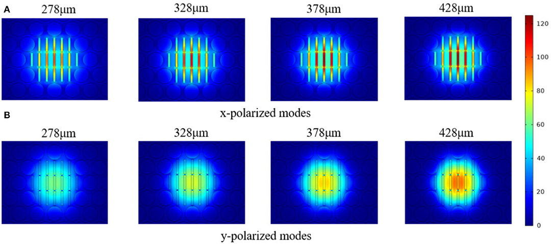
Figure 2. The mode field distribution of the proposed THz-PCF for (A) x-polarized modes and (B) y-polarized modes for different Dcore at the frequency of 1.5 THz when P = 30%.
Here, the key propagation properties of the proposed PCF-THz waveguide are numerically simulated to calculate the effective indices of the electromagnetic modes based on FV-FEM. An antireflective layer that is also known as a perfectly matched layer (PML) is used at the outer boundary of the waveguide to reduce the effect of the surrounding environment and materials to the confinement loss [51]. The thickness of the PML is set to 12.5% of the total fiber radius to easier meet the fabrication possibilities. Here, according the functional relationship between the effective refractive index (RI) and the PML thickness as shown in Figure 3, the influence of PML thickness on the real part of RI can be ignored, while the influence on the imaginary part of RI cannot be ignored. The variation of dispersion and birefringence depends directly on the real part of RI, but the confinement loss depends on the imaginary part of RI, thus the change of PML thickness has almost no effect on dispersion and birefringence, the effect on the confinement loss cannot be ignored. For all the optimum parameters, we found 5, 12.5, and 20% of PML thickness show a lower imaginary part of RI. As 5% of PML thickness creates fabrication complexity and 20% of PML thickness makes the fiber bulky. Therefore, we chose 12.5% of PML thickness for our proposed fiber.
Birefringence and dispersion are two kinds of crucial properties that limit the quality of signal transmission in high speed THz communication systems. One of our design goals is to make the PCF operate with high birefringence and ultra-low flat dispersion. Therefore, it is more important to check the influence of different parameters such as core diameter (Dcore) and core porosity (P) on birefringence and dispersion in THz waveguide design.
Firstly, to obtain higher birefringence for the proposed THz-PCF, the level of birefringence should be significant. Here, the mode birefringence (B) is first analyzed, which is defined as the difference of the real parts of RI for the two fundamental orthogonal polarization modes and can be expressed as [36]:
where, nx and ny are RI of x- and y- polarized modes, respectively. The birefringence (B) on Dcore and core porosity are demonstrated in Figure 4, with higher birefringence on the level of 10−2. Figure 4A depicts the birefringence as a function of frequency for different Dcore at P = 30%. It can be seen from Figure 4A that the birefringence of the proposed THz-PCF increases gradually with the increase of the core-area diameter and presents a flat trend in a frequency range of 1.2–1.8 THz. The reason for this can be understood as the fact that the ratio of length to width of the rectangular air holes in the porous core increases when Dcore is increased. Therefore, the asymmetry induced in the porous-core area becomes stronger and leads to an enhancement of birefringence. When Dcore = 378 μm, the birefringence values locate above 7.0 × 10⁻² over the frequency range of 1.2–1.8 THz, and an ultra-high birefringence of 7.1 × 10⁻² is obtained at f = 1.5 THz. Then, with a fixed Dcore = 378 μm, the birefringence as a function of frequency for different core porosity is shown in Figure 4B, in which it is observed that the birefringence increases when the core porosity is decreased. When the core porosity is 30%, birefringence higher than 6.0 × 10⁻² is obtained over the frequency range 0.9–2.0 THz, with the highest birefringence of 7.1 × 10⁻² at 1.5 THz. The vital unique feature of the proposed THz-PCF presents a nearly constant birefringence over a wide frequency region from 1.2 to 2 THz, which is very significant for a polarization-maintaining THz transmission application.
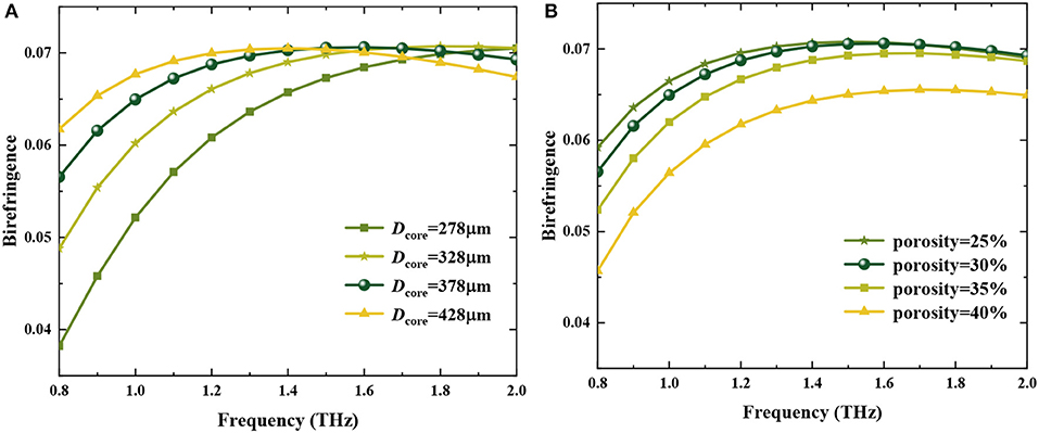
Figure 4. Birefringence vs. frequency of the proposed fiber (A) for different Dcore at P = 30%, (B) for different core porosity at Dcore = 378 μm.
Secondly, dispersion is another important property in the application of THz-PCF, which should be as low as possible to reduce the bit error rate and avoid optical signal overlap due to pulse broadening. Near-zero ultra-flat dispersion is particularly suitable for the effective transmission of broadband waves [36]. In general, dispersion can occur either for the used bulk material (material dispersion) or for the waveguide structure (waveguide dispersion). Here, we consider only the waveguide dispersion because the material absorption loss is negligible for TOPAS [37], which can be expressed by [13]:
where, ω indicates the angular frequency, and neff is the RI of the fiber. Obviously, dispersion mainly depends on the change of the RI of the waveguide with frequency.
The dispersion profile of the proposed THz-PCF as a function of frequency for different core-diameter Dcore and core porosity are shown in Figure 5. Figure 5A describes β2 as a function of frequency for different Dcore at P = 30%. It can be seen that the dispersion is decreasing and the corresponding flattened region becomes broader gradually when Dcore increases. There is a visible difference of dispersion values between the x- and y-polarized modes, the dispersion value of x-polarized is higher than that of y-polarized, which is consistent with the fact that the mode power flux is tightly confined in the core for y-polarized modes than x-polarized modes because of the asymmetrical PCF structure. It is worth noting that the flattened dispersion range nearly covers the interesting frequency range from 1.1 to 2.0 THz when Dcore = 378 μm, which coincides with the frequency range of high birefringence. The variation of the dispersion value is ±0.02 ps/THz/cm for the y-polarized mode and ±0.05 ps/THz/cm for the x-polarized mode. Furthermore, the dependence of β2 on core porosity is shown in Figure 5B with a fixed Dcore = 378 μm. It is obvious that the dispersion value is decreasing and getting closer to zero with the reducing values of core porosity, which is the fact that more mode power flux is confined in the core for lower core porosity. In addition, we can also see that the y-polarized mode exhibits a lower dispersion than the x-polarized mode in the flattened dispersion region. Also, a near-zero ultra-flattened dispersion value of −0.01 ± 0.02 ps/THz/cm for the y-polarized mode and 0.2 ± 0.05 ps/THz/cm for the x-polarized mode can be obtained in the whole interesting frequency range from 1.1 to 2.0 THz for P = 30%. Compared to the reported THz-PCF in the literature [35–46, 50–53], the proposed THz-PCF presents a near-zero ultra-flat dispersion over the widest frequency range of 1.1–2.0 THz with two zero-dispersion points (1.06 THz and 1.74 THz). So Dcore= 378 μm and porosity = 30% is selected as optimal design parameters.
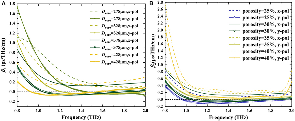
Figure 5. Dispersion vs. frequency of the proposed PCF (A) for different Dcore at P = 30%, (B) for different core porosity at Dcore = 378 μm.
Then, it is well to know that waveguides with low absorption loss and high-power fractions at a higher frequency would be a good candidate for the application in broadband transmission in the THz regime. The losses will arise when light propagates through the whole length of the fiber. Effective material loss (EML, αeff) is one of the major issues that causes operating signal energy dissipation, which can be numerated by Equation (3) [13]:
where ε0 is the permittivity and μ0 is the permeability of the vacuum. N = 1.525 is the refractive index of the material, and Sz is the z-component of the Poynting vector, which is defined as , where E and H are the electric and magnetic field components of the transmitted power, respectively. The integration in the numerator of Equation (3) covers the material regions of TOPAS, and in the denominator covers all regions. Confinement loss is also a critical factor that limits the propagation length of the transmitted signal through the THz waveguide, which has a direct relationship with the number of air holes used, the spacing between adjacent air holes, and the number of rings in the cladding. In practice, confinement loss should be as low as possible to obtain a longer propagation length for the THz signal, which can be calculated from Equation (4) [40, 50]:
where f is the operating frequency, Im(neff) represents an imaginary part of the refractive index. Figures 6A,B gives EML and confinement loss as a function of frequency for different core porosity.
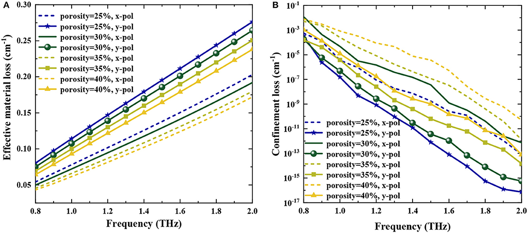
Figure 6. (A) EML and (B) confinement loss vs. frequency for the proposed THz-PCF at different core porosity and fixed Dcore = 378 μm.
It is observed that EML increases with an increase of frequency for both x- and y-polarized modes, and the x-polarized mode exhibits lower absorption loss than the y-polarized mode (see Figure 6A). It could be explained by the fact that the majority of the light is propagated through the porous-core area in the y-polarized mode, which is consistent with the power flow distributions shown in Figure 2. Also, EML decreased with the increase of core porosity at a fixed frequency, with the reason being more light is propagated through the air holes in the core rather than through the material. Note that, for the optimal parameters (Dcore = 378 μm and P = 30%), EML is found as 0.141 cm−1 and 0.201 cm−1 for x- and y-polarized modes at 1.5 THz, respectively. Confinement loss is decreased for both x- and y-polarized modes with the increase of frequency (see Figure 6B). Confinement loss in the y-polarized mode is less than the x-polarized mode due to better mode constraint for y instead of x. As a result, less mode power leaks out to the cladding, and confinement loss decreases. It is worth noting that the confinement loss is found to be 7.08 × 10⁻¹² cm−1 and 5.74 × 10⁻⁹ cm−1 for the y- and x-polarized modes at 1.5 THz under the optimal parameters, respectively.
The mode power fraction presents the amount of electromagnetic power propagating through different regions of the fiber, which can be calculated by Equation (5) [31, 45]. Achieving a higher core power ratio is our goal.
where x in the numerator defines the area of the region of interest, and the denominator defines the total area. The effective mode area (Aeff) is measured quantitatively by the distributed electric field energy inside the waveguides, which can be expressed by [40]:
where is called the transverse electric field intensity in the proposed fiber. Figures 7A,B show mode power fraction and effective mode area as a function of frequency for different core porosity.
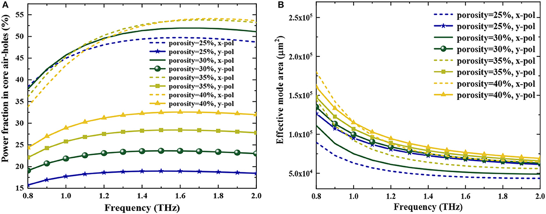
Figure 7. (A) Power fraction in core air holes, (B) Effective mode area vs. frequency for the proposed THz-PCF at different core porosity and fixed Dcore = 378 μm.
The mode power fraction increases with the increase of core porosity when the frequency is constant, and the core power fraction in the y-polarized mode is smaller than the x-polarized mode, which corresponds to the result of the EML (see Figure 7A). It was found the power fraction remains unchanged over a wider frequency range from 1.2 to 2 THz, which is very necessary for broadband THz transmission by minimizing confinement loss. More than 52% of the power fraction is produced at 1.5 THz for the optimum THz-PCF structure. In addition, the effective mode area (Aeff) decreases with the increase of frequency and increases with the increase of core porosity (see Figure 7B). Therefore, the transmission quality of the light beam could be improved markedly by decreasing core porosity. Meanwhile, the modes would be more confined in the fiber core region. When Dcore = 378 μm and P = 30%, Aeff are 5.13 × 10⁻⁸ m2 and 6.95 × 10⁻⁸ m2 for the x- and y-polarized modes at 1.5 THz, respectively.
From the above discussions, it can be clearly expressed that the proposed THz-PCF presents a near-zero ultra-flattened dispersion value of −0.01 ± 0.02 ps/THz/cm and an ultra-high birefringence of 7.1 × 10⁻² over broader frequency ranges of 1.1–2.0 THz, while it has lower confinement loss of 7.08 × 10⁻¹² cm−1 and a higher power fraction of 52%, which will be effective for broadband THz transmission systems. Table 1 represents the comparisons among several fundamental properties of the proposed THz-PCF with Ref. [35–38, 40, 42, 43, 45, 51–53]. It is obviously that it has excellent performance in the fields of high birefringence, ultra-low flat dispersion, and low confinement loss than others reported in the literature. The proposed THz-PCF with an ultra-low flat dispersion and a birefringence higher than 7.0 × 10⁻² over a wide frequency range of 1.1–2 THz will play an important role in ultra-wideband polarized THz transmission system.
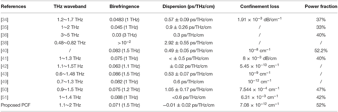
Table 1. Comparison among several fundamental properties of the proposed THz waveguide with those reported in the literature.
The proposed THz-PCF has the possibility to be fabricated easily due to its simple structure, consisting of a circular air hole in the cladding and a rectangular air hole in the core. Especially, more recent technologies, such as extrusion and 3D printing, are demonstrated to fabricate different complex-shaped asymmetrical air holes [43]. The extrusion technique developed by J. Wang et al. [47] offers fabrication freedom for complex structures including crystalline and amorphous PCFs. The sol-gel casting technique and in-situ polymerization demonstrated in [48, 49] offers the design freedom to fabricate micro-structured PCFs where air hole size and spacing can be adjusted independently. Therefore, it can be anticipated that the verified techniques should be enough to fabricate the proposed structure.
In conclusion, a near-zero ultra-flat dispersion and high birefringence porous-core THz-PCF based on TOPAS is designed for application in broadband THz transmission systems. It is composed of a porous core of rectangular air holes to induce high birefringence and cladding with hexagonal lattice circular air holes to enhance the guided-mode confinement. Its guiding properties are characterized by various geometrical parameters including different values of core porosity and core diameters over frequencies in the THz regime. In a broad frequency range of 1.1–2.0 THz, a birefringence of higher than 7.1 × 10⁻² and an ultra-low flattened dispersion of −0.01 ± 0.02 ps/THz/cm could be achieved simultaneously. The proposed fiber also has other advantageous profiles, such as the good mode confinement due to low EML (<0.2 cm−1), ultra-low confinement loss (~7.08 × 10⁻¹² cm−1), and high-power fraction of the core (~52%). These excellent guiding characteristics of the proposed THz-PCF can potentially make it extremely suitable for multi-functions such as efficient THz transmission, THz sensing, and other optical system designs.
All datasets generated for this study are included in the article/supplementary material.
YZ and XJ wrote the manuscript. DQ was a doctoral student who directed graduates during theoretical simulations. LX was a graduate student who implemented the simulation scheme. All the authors contributed to the conception and revised the text.
This work was supported by the National Science Foundation of China (No. 61605106), the International Science & Technology Cooperation and Exchanges Project of Shaanxi (No. 2018KW-016), the Key Sciences and Technology Project of Baoji City (No. 2015CXNL-1-3), the Open Research Fund of State Key Laboratory of Transient Optics and Photonics (No. SKLST201802), and the Science and Technology Project of Xianyang City (No. 2018K02-60).
The authors declare that the research was conducted in the absence of any commercial or financial relationships that could be construed as a potential conflict of interest.
1. Chen Q, Jiang ZP, Xu GX, Zhang XC. Near-field terahertz imaging with a dynamic aperture. Opt. Lett. (2000) 25:1122–24. doi: 10.1364/OL.25.001122
2. Liu HB, Zhong H, Karpowicz N, Chen Y, Zhang X C. Terahertz spectroscopy and imaging for defense and security applications. Proc IEEE. (2007) 95:1514–27. doi: 10.1109/JPROC.2007.898903
3. Awad MM, Cheville RA. Transmission terahertz waveguide based imaging below the diffraction limit. Appl Phys Lett. (2005) 86:221107. doi: 10.1063/1.1942637
4. Png GM, Falconer RJ, Abbott D. Tracking aggregation and fibrillation of globular proteins using terahertz and far-infrared spectroscopies. IEEE Trans. Terahertz Sci. Technol. (2016) 6:45–53. doi: 10.1109/TTHZ.2015.2505900
5. Woodward RM, Wallace VP, Arnone DD, Linfield EH, Pepper M. Terahertz pulsed imaging of skin cancer in the time and frequency domain. J Biol Phys. (2003) 29: 257–9. doi: 10.1023/A:1024409329416
6. Laman N, Harsha SS, Grischkowsky D, Melinger JS. 7 GHz resolution waveguide THz spectroscopy of explosives related solids showing new features. Opt Express. (2008) 16:4094–105. doi: 10.1364/OE.16.004094
7. Mizuno M, Fukunaga K, Saito S, Hosako I. Analysis of calcium carbonate for differentiating between pigments using terahertz spectroscopy. J Eur Opt Soc Rapid Publ. (2009) 4:09044. doi: 10.2971/jeos.2009.09044
8. Sultana J, Islam M S, Islam MR, Abbott D. High numerical aperture, highly birefringent novel photonic crystal fibre for medical imaging applications. Electron Lett. (2017) 54:61–2. doi: 10.1049/el.2017.3694
9. Kawase K, Ogawa Y, Watanabe Y, Inoue H. Non-destructive terahertz imaging of illicit drugs using spectral fingerprints. Opt Express. (2003) 11:2549–54 doi: 10.1364/OE.11.002549
10. Yu C, Fan S, Sun Y, Pickwell-MacPherson E. The potential of terahertz imaging for cancer diagnosis: a review of investigations to date. Quant Imaging Med Surg. (2012) 2:33–45. doi: 10.3978/j.issn.2223-4292.2012.01.04
11. Islam MS, Sultana J, Ahmed K, Dinovitser A, Islam MR, Ng BWH, Abbott D. A novel approach for spectroscopic chemical identification using photonic crystal fiber in the terahertz regime. IEEE Sens J. (2018) 18:575–82. doi: 10.1109/JSEN.2017.2775642
12. Nagatsuma T, Ducournau G, Renaud CC. Advances in terahertz communications accelerated by photonics. Nat Photonics. (2016) 10:371–79. doi: 10.1038/nphoton.2016.65
13. Islam MS, Sultana J, Rana S, Islam MR, Faisal M, Kaijage SF, et al. Extremely low material loss and dispersion flattened TOPAS based circular porous fiber for long distance terahertz wave transmission. Opt Fiber Technol. (2017) 34:6–11. doi: 10.1016/j.yofte.2016.11.014
14. Zaytsev K I, Kudrin KG, Karasik VE, Reshetov IV, Yurchenko SO. In vivo terahertz spectroscopy of pigmentary skin nevi: pilot study of non-invasive early diagnosis of dysplasia. Appl Phys Lett. (2015) 106:053702. doi: 10.1063/1.4907350
15. Reid CB, Fitzgerald A, Reese G, Goldin R, Tekkis P, Kelly PS, et al. Terahertz pulsed imaging of freshly excised human colonic tissues. Phys Med Biol. (2011) 56:4333–53. doi: 10.1088/0031-9155/56/14/008
16. Ashworth PC, Pickwell-MacPherson E, Provenzano E, Pinder SE, Purushotham AD, Pepper M, et al. Terahertz pulsed spectroscopy of freshly excised human breast cancer. Opt Express. (2009) 17:12444–454. doi: 10.1364/OE.17.012444
17. Clothier RH, Bourne N. Effects of THz exposure on human primary keratinocyte differentiation and viability. J Biol Phys. (2003) 29:179–185. doi: 10.1023/A:1024492725782
18. Xu WX, Guo PL, Li XH, Hui ZQ, Wang Y, Shi Z, et al. Sheet-structured bismuthene for near infrared dual-wavelength harmonic mode-locking. Nanotechnology. (2020) 31:225209. doi: 10.1088/1361-6528/ab7674
19. Guo PL, Li XH, Chai T, Feng T, Ge Y, Song Y, Wang Y. Few-layer bismuthene for robust ultrafast photonics in C-Band optical communications. Nanotechnology. (2019) 30:354002. doi: 10.1088/1361-6528/ab2150
20. Li XH, Liu XM, Mao D, Hu X, Lu H. Tunable and switchable multi wavelength fiber lasers with broadband range based on nonlinear polarization rotation technique. Opt Eng. (2010) 49:094303. doi: 10.1117/1.3485754
21. Li XH, Wang YS, Zhao W, Liu X, Wang Y, Tsang YH, et al. All-fiber dissipative solitons evolution in a compact passively Yb-doped mode-locked fiber laser. J Lightwave Tech. (2012) 30:2502–7. doi: 10.1109/JLT.2012.2201210
22. Li XH, Wang YS, Zhang W, Zhao X, Hu H, Yang Z, et al. Low-repetition-rate ytterbium-doped fiber laser based on a CFBG from large anomalous to large normal dispersion. Laser Phys. (2011) 21:2112–7. doi: 10.1134/S1054660X11210110
23. Wang K, Mittleman DM. Metal wires for terahertz waveguiding. Nature. (2004) 432:376–79. doi: 10.1038/nature03040
24. Bowden B, Harrington JA, Mitrofanov O. Silver/polystyrene coated hollow glass waveguides for the transmission of terahertz radiation. Opt Lett. (2007) 32:2945–47. doi: 10.1364/OL.32.002945
25. Chen LJ, Chen H, Kao T, Lu J, Sun C. Low loss subwavelength plastic fiber for terahertz wave guiding. Opt Lett. (2006) 31:308–10. doi: 10.1364/OL.31.000308
26. Skorobogatiy M, Dupuis A. Ferroelectric all-polymer hollow Bragg fibers for terahertz guidance. Appl Phys Lett. (2007) 90:113514. doi: 10.1063/1.2713137
27. Zhao G, Mors MT, Wenckebach T. Terahertz dielectric properties of polystyrene foam. J Opt Soc Am B. (2002) 19:1476–79. doi: 10.1364/JOSAB.19.001476
28. Hossain A, Namihira Y. Light source design using Kagome lattice hollow core photonic crystal fibers. Opt Rev. (2014) 21:490–95. doi: 10.1007/s10043-014-0076-z
29. Pristinski D, Du H. Solid-core photonic crystal fiber as a Raman spectroscopy platform with a silica core as an internal reference. Opt Lett. (2006) 31:3246–8. doi: 10.1364/OL.31.003246
30. Sultana J, Islam Md S, Atai J, Islam MR, Abbott D. Near zero dispersion flattened, low-loss porous-core waveguide design for terahertz signal transmission. Opt Eng. (2017) 56:076114. doi: 10.1117/1.OE.56.7.076114
31. Islam MS, Sultana J, Atai J, Islam MR, Abbott D. Dsign and characterization of a low-loss, dispersion-flattened photonic crystal fiber for terahertz wave propagation Optik. (2017) 45:398–406. doi: 10.1016/j.ijleo.2017.07.061
32. Islam MS, Rana S, Islam MR, Faisal M, Rahman H, Sultana J. Porous core photonic crystal fiber for ultra-low material loss in THz regime. IET Commun. (2016) 10:2179–83. doi: 10.1049/iet-com.2016.0227
33. Islam S, Islam MR, Faisal M, Arefin ASMS, Rahman H, Sultana J, Rana S. Extremely low-loss, dispersion flattened porous-core photonic crystal fiber for terahertz regime. Opt Eng. (2016) 55:076117. doi: 10.1117/1.OE.55.7.076117
34. Islam MS, Sultana J, Atai J, Abbott D, Rana S, Islam MR. Ultra low-loss hybrid core porous fiber for broadband applications. Appl Opt. (2017) 56:1232–37. doi: 10.1364/AO.56.001232
35. Islam R, Habib MS, Hasanuzzaman GKM, Ahmad R, Rana S, Kaijage SF. Extremely high-birefringent asymmetric slotted core photonic crystal fiber in THz regime. IEEE Photonics Technol Lett. (2015) 27:2222–25. doi: 10.1109/LPT.2015.2457673
36. Hasan MR, Anower MdS, Islam MA, Razzak SMA. Polarization-maintaining low-loss porous-core spiral photonic crystal fiber for terahertz wave guidance. Appl Opt. (2016) 55:4145–52. doi: 10.1364/AO.55.004145
37. Islam R, Habib MS, Hasanuzzaman GKM, Rana S, Sadath M. A Novel porous fiber based on dual-asymmetry for low-loss polarization maintaining THz wave guidance. Opt Expr. (2016) 41:440–3. doi: 10.1364/OL.41.000440
38. Wu Z, Shi Z, Xia H, Zhou X, Deng Q, Huang J, et al. Design of highly birefringent and low-loss oligo porous-core THz photonic crystal fiber with single circular air-hole unit. IEEE Photonics J. (2016) 8:4502711. doi: 10.1109/JPHOT.2016.2633229
39. Islam MS, Sultana J, Cordeiro CMB, Cruz ALS, Dinovitser A, Ng BWH, et al. Broadband characterization of glass and polymer materials using THz-TDS. IEEE Photonics. (2019) 978:1–3. doi: 10.1109/IRMMW-THz.2019.8874013
40. Islam R, Habib MS, Hasanuzzaman GKM, Rana S, Sadath MA, Markos C. A novel low-loss diamond-core porous fiber for polarization maintaining terahertz transmission. IEEE Photonics Technol. Lett. (2016) 28:1537–40. doi: 10.1109/LPT.2016.2550205
41. Chen N, Liang J, Ren L. High-birefringence, low-loss porous fiber for single-mode terahertz-wave guidance. Appl Opt. (2013) 52:5297–302. doi: 10.1364/AO.52.005297
42. Islam MR, Kabir MF, Talha KMA, Arefin MS. Highly birefringent honeycomb cladding terahertz fiber for polarization-maintaining applications. Opt Engineering. (2020) 59:016113. doi: 10.1117/1.OE.59.1.016113
43. Islam MS, Sultana J, Dinovitser A, Faisal M, Islam MR, Ng BWH, Abbott D. Zeonex-based asymmetrical terahertz photonic crystal fiber for multichannel communication and polarization-maintaining applications. Appl Opt. (2018) 57:666–72. doi: 10.1364/AO.57.000666
44. Paul BK, Ahmed K. Highly birefringent TOPAS based single mode photonic crystal fiber with ultra-low material loss for Terahertz applications. Optical Fiber Technol. (2019) 53:102031. doi: 10.1016/j.yofte.2019.102031
45. Sultana J, Islam MS, Faisal M, Islam MR, Ng WH, Ebendorff-Heidepriem H, et al. Highly birefringent elliptical core photonic crystal fiber for terahertz application. Opt Commun. (2018) 407:92–6. doi: 10.1016/j.optcom.2017.09.020
46. Heidepriem HE, Schuppich J, Dowler A, Lima-Marques L, Monro TM. 3D-printed extrusion dies: a versatile approach to optical material processing. Opt Mater Express. (2014) 4:1494–504. doi: 10.1364/OME.4.001494
47. Wang J, Yang XH, Wang LL. Fabrication and experimental observation of monolithic multi-air-core fiber array for image transmission. Opt Express. (2008) 16:7703–08. doi: 10.1364/OE.16.007703
48. Zhang YN, Li K, Wang LL, Ren LY, Zhao W, Miao RC. Casting preforms for micro-structured polymer optical fiber fabrication. Opt Expr. (2006) 14:5541–47. doi: 10.1364/OE.14.005541
49. Ma T, Andrey M, Wang LL. Maksim Skorobogatiy, Graded index porous optical fibers dispersion management in terahertz range. Opt Expr. (2015) 23:7856–69. doi: 10.1364/OE.23.007856
50. Luo J, Tian F, Qu H, Li L, Zhang J, Yang X, Yuan L. Design and numerical analysis of a THz square porous-core photonic crystal fiber for low flattened dispersion, ultrahigh birefringence. Appl Opt. (2017) 56:6993–7001. doi: 10.1364/AO.56.006993
51. Habib MA, Reza MS, Abdulrazak LF, Anower MS. Extremely high birefringent and low loss microstructure optical waveguide: design and analysis. Opt Commun. (2019) 446:93–9. doi: 10.1016/j.optcom.2019.04.060
52. Yang TY, Ding C, Ziolkowski RW, Guo YJ. A scalable THz photonic crystal fiber with partially-slotted core that exhibits improved birefringence and reduced loss. J Lightwave Technol. (2018) 36:3408–17. doi: 10.1109/JLT.2018.2842825
Keywords: fiber optics, far infrared or terahertz, microstructured fibers, fibers, polarization-maintaining, polymers
Citation: Zhang Y, Jing X, Qiao D and Xue L (2020) Rectangular Porous-Core Photonic-Crystal Fiber With Ultra-Low Flattened Dispersion and High Birefringence for Terahertz Transmission. Front. Phys. 8:370. doi: 10.3389/fphy.2020.00370
Received: 06 July 2020; Accepted: 31 July 2020;
Published: 08 October 2020.
Edited by:
Xiaohui Li, Shaanxi Normal University, ChinaReviewed by:
Xiaoyu Liu, Xi'an University of Posts and Telecommunications, ChinaCopyright © 2020 Zhang, Jing, Qiao and Xue. This is an open-access article distributed under the terms of the Creative Commons Attribution License (CC BY). The use, distribution or reproduction in other forums is permitted, provided the original author(s) and the copyright owner(s) are credited and that the original publication in this journal is cited, in accordance with accepted academic practice. No use, distribution or reproduction is permitted which does not comply with these terms.
*Correspondence: Yani Zhang, eWFuaXpoYW5nMUAxNjMuY29t; Dun Qiao, ZHVuLnFpYW9Ac291dGh3YWxzZS5hYy51aw==
†These authors have contributed equally to this work and share first authorship
Disclaimer: All claims expressed in this article are solely those of the authors and do not necessarily represent those of their affiliated organizations, or those of the publisher, the editors and the reviewers. Any product that may be evaluated in this article or claim that may be made by its manufacturer is not guaranteed or endorsed by the publisher.
Research integrity at Frontiers

Learn more about the work of our research integrity team to safeguard the quality of each article we publish.