 Chun Ni
 Changqing Liu2
94% of researchers rate our articles as excellent or good
Learn more about the work of our research integrity team to safeguard the quality of each article we publish.
Find out more
ORIGINAL RESEARCH article
Front. Phys. , 21 August 2020
Sec. Optics and Photonics
Volume 8 - 2020 | https://doi.org/10.3389/fphy.2020.00316
This article is part of the Research Topic Recent Progress in Surface Electromagnetic Modes View all 17 articles
A broadband high gain polarization reconfigurable antenna based on metasurface has been presented. The antenna is composed of a planar metasurface, a slot antenna and an air cavity. The metasurface is made up of 64 identical patches, and all the patches are on the top surface of the substrate. The spatial equivalent circuit of the metasurface is discussed and two approximate calculation formulas of the equivalent circuit are obtained. The antenna can be reconfigured to linear polarization, left-hand and right-hand circular polarizations by adjusting the relative positions between the metasurface and the planar slot antenna. The gain of the antenna is improved. In order to verify these methods, the antenna is studied and designed to operate at around 11GHz. The simulated and measured results show that the 3dB axis ratio bandwidth is 10–12 GHz (fractional bandwidth 18.18%) and maximum gain of 14.6 dBi.
Metamaterials, such as metasurface (MS), electromagnetic band gap (EBG), photonic band gap (PBG), frequency selective surface (FSS) and left handed metamaterials (LFM), are commonly designed by arranging a number of electrically small scatterers in regular or irregular periods within a space region to obtain some special electromagnetic behaviors [1–5]. In recent years, reconfigurable antennas based on metasurface have been attracting a wide attention of researchers [6–10]. Reconfigurable antennas generally include operating frequency, radiation pattern, and polarization modes tunability, which can well meet the complex communication systems and multitasking demands [11–13]. Polarization reconfigurable antennas are usually able to achieve polarization mode transitions. For example, the antenna can be reconfigured to left-hand circular polarization (LHCP), right-hand circular polarization (RHCP) and linear polarization [14–17]. The direction of the electric field vector is changed at the time of reconstruction. Frequency reconfigurable antennas are very useful owing to their tunable operating frequency, which can be classified into two types, band switching and continuous tuning, respectively [18–21]. The radiation pattern of an antenna can be classified into omnidirectional radiation, bidirectional radiation, unidirectional radiation and multidirectional radiation. Radiation pattern reconfigurable antennas can usually be switched from one radiation pattern to another.
Just as a two-dimensional equivalent of metamaterial, metasurface, which cannot be really found in the nature, is essentially periodic arrangements of scatterers or apertures in order to achieve the characteristics of specialized engineering [22, 23]. Research shows that MS can be used to enhance the performance of antennas. Thus, much research work has been carried out in the field of improving antenna gain, achieving polarization reconfigurable and frequency reconfigurable antennas by using MS.
In literature [24], a frequency and polarization reconfigurable antenna consisting of a frequency reconfigurable MS, a polarization reconfigurable MS and a microstrip patch antenna with the same diameter is proposed. The polarization reconfigurable MS consists of periodic corner-truncated square elements placed on the upper surface of the frequency reconfigurable MS, and the microstrip patch antenna placed in the bottom layer as a source antenna. By rotating the frequency reconfiguration MS, the designed antenna has a tuning range of 4.0–4.35 GHz. By rotating the polarizable reconfigurable surface, the designed antenna can realize the transformation of linear and circular polarization at 5.0–5.2GHz (relative bandwidth 4%). In [25], the studies of polarization reconfigurable antenna with a slot antenna and an asymmetric corss shaped MS are conducted. The linear polarization of the slot antenna is reconfigured into LHCP and RHCP by rotating the MS around the center of the slot antenna. The designed polarization reconfigurable antenna has a 3dB axis ratio (AR) bandwidth of 4.29–4.41 GHz (relative bandwidth 2.7%). In [22], A radiation pattern reconfigurable antenna based on MS is proposed. The operating frequency range of the designed radiation pattern reconfigurable antenna is 5.4–5.6 GHz. A low profile broadband circularly polarized MS antenna was proposed in [26]. The MS consisting of 4 × 4 square metal patches to realize the miniaturization of the antenna.The 3 dB axial ratio bandwidth is 1.4–1.62 GHz (relative bandwidth 14.5%).
The operating bandwidth of the previously published literature with polarization reconfigurable and radiation pattern reconfigurable antenna is often subject to the restriction of the structure of MS, As is in [26], the 3 dB AR is only 14.5%. In this paper, a polarization reconfigurable antenna using an improved MS is proposed. When the antenna operates in circular polarization, there will be three inflection points in the AR curve. Thus, the 3 dB AR bandwidth is expanded greatly.
In this paper, a reconfigurable antenna using an improved MS is proposed. The 3 dB AR bandwidth is expanded greatly. To clearly show that this antenna can provide circular polarization radiation, the vector electric field at different phases from 0 to 360 degrees, at the antenna aperture in the far field is analyzed. Our work extracts and analyses the equivalent circuit parameters of the improved MS. In the new design, Fabry-Perot cavity antenna and MS are combined to expand the bandwidth of antenna, improve the gain of antenna, and realize polarization reconfiguration.
As is shown in Figure 1, the proposed MS is made up of 64 identical periodic patches, and all the patches are on the top surface of the dielectric substrate. In Figure 1A, the structure within the area enclosed by the red curve can be considered as a unit cell. In order to analyze the polarization properties of the MS, the unit cell is enlarged and redrawn, as is presented in Figure 1B.
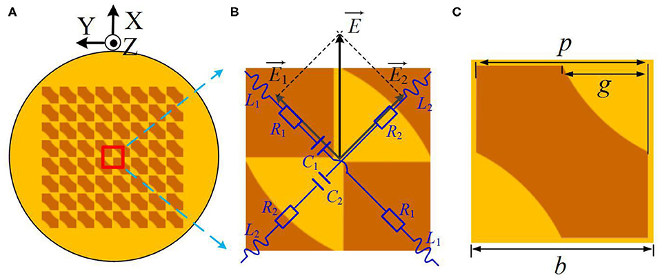
Figure 1. Geometry of proposed MS. (A) top view of the MS, (B) Unit cell with corners truncated, and (C) Schematic with the size parameters of the patch.
The perpendicular E-field components broken down by the MS will cause two different impedances. The expression for two impedances is shown in Equations (1) and (2).
The spatial equivalent circuit of the metal microstrip structure is discussed in literature [27]. The equivalent circuit of the metasurface is analyzed and two approximate calculation formulas of the equivalent circuit are obtained. As is shown in Equations (3) and (4), ε0 is the permittivity and μ0 is the permeability of the free space; εr is dielectric constant of substrate; γg is the relative distance of two patches, which is related to the dimension of the patch and the cutting part; η is length of the truncated patch; p is the length of the patch; b is the length of the unit cell.
According to Equations (3) and (4), when γg increases, the L2 increases and the C2 decreases. Thus, the value of XZ2 becomes large, making Z2 less capacitive than Z1. The phase difference between Z1 and Z2 can be achieved by varying the dimension of the truncated corners. When the unit cell is truncated such that |Z1| = |Z2|, and , then |E1| = |E2| and . The antenna will be RHCP. As is shown in Figure 2B, when the MS is rotated 45° or 135° in the counterclockwise direction, the antenna is changed to LP. When the rotation angle is 90°, the antenna is reconfigured to LHCP. The schematic assembly of antenna is drawn in Figure 2A. It can be seen that the reconfigurable antenna presented in this paper consists of a slot antenna, a supersurface and an air cavity. These three components together form the Fabry-Perot cavity antenna in structure.
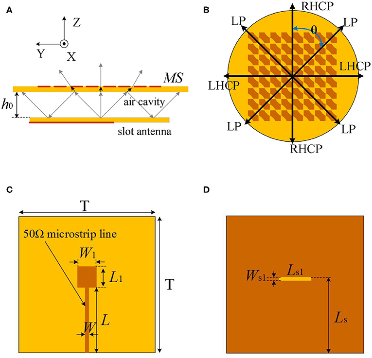
Figure 2. Geometry of proposed antenna. (A) Assembly schematic, (B) Polarization of the antenna, (C) Feeder line of slot antenna, and (D) Surface of slot antenna.
The property of the metasurface layer is highly relevant with the characteristics of the fabry-perot resonator antenna. In addition, the frequency resonance of an fabry-perot resonator antenna can be described as
where φm and φr, respectively, represent the reflection phases of the metasurface layer and the ground plane, and h0 is the height of the fabry-perot cavity. Supposing that the ground plane is perfectly electric conducting (φr = –π) and the reflection phase of the metasurface layer varies around –π, according to equation (5), the fabry-perot cavity has a minimum height h of ~λ/2 when the fabry-perot resonator antenna operates at the first resonance (n = 0).
As we know, the Fabry-Perot cavity can improve the gain of antenna greatly. In this design, a slot patch antenna which is chosen has the potential of easy feed, stable transverse radiation and wide bandwidth. Complete schematic with the dimensions of feeder line of the source antenna is drawn in Figure 2C. The surface source antenna is drawn in Figure 2D.
To demonstrate the circular polarization (CP) characteristics of MS, the simulated current distribution on the MS antenna at different time points is shown in Figure 3. It is obvious that the electric field vector distribution varies and rotates with time. Numerical simulations have been performed by using the full wave electromagnetic simulator HFSS. Figure 3A shows the direction of rotation of the electric field vector of the metasurface's unit cell when θ = 0°. According to the rotation direction of the electric field vector, the electric field is RHCP.
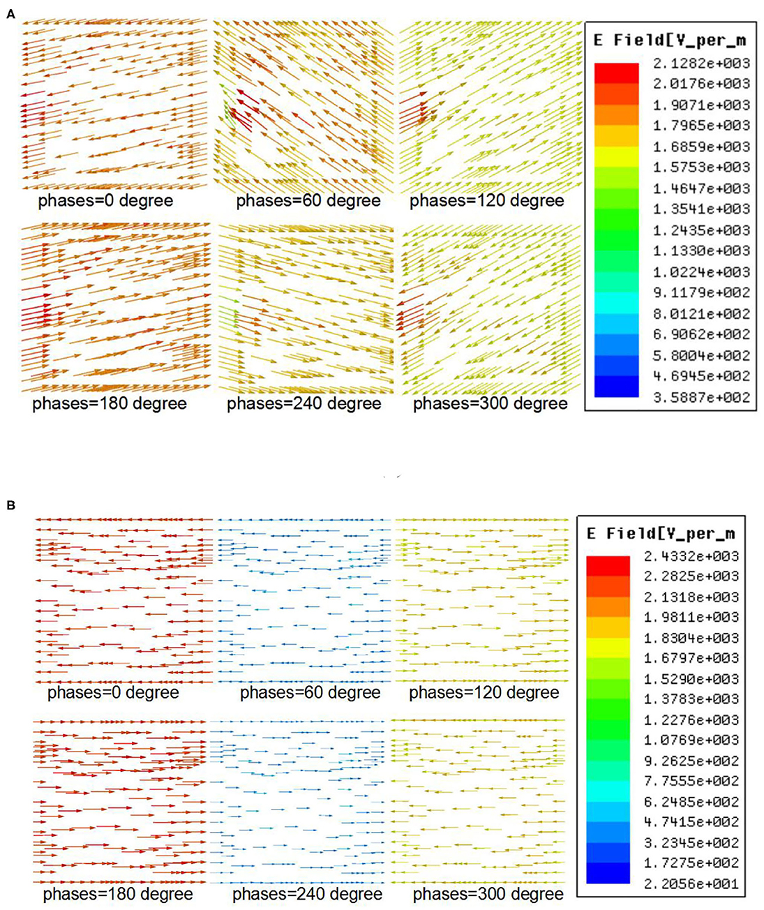
Figure 3. Electric field distribution at f = 11 GHz for the unit cell of the proposed MS. (A) θ = 0° and (B) θ = 45°.
Figure 3B shows the direction of the electric field vector when θ = 45°. According to the direction of the electric field vector, the electric field is LP at this time. The simulated reflection and transmission coefficients of the metasurface's unit cell under normal incidence are plotted in Figure 4.
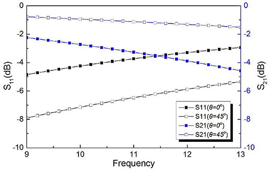
Figure 4. The simulated amplitude of the reflection and transmission coefficients of the metasurface's unit cell.
As described above, the size of the h0 is affected by the reflection phase of the metasurface. However, the reflection phase of the metasurface also changes with frequency. The simulation results of reflection phase of the metasurface are shown in Figure 5. According to the size of ho, the phase difference caused by the path difference can be calculated. Figure 5 also shows the path difference φΔ, the reflection phase φm of the metasurface and the total phase difference Ψ at different frequencies. As shown in Figure 5, the total phase difference Ψ is close to 0 at 10.5 GHz when θ = 45°, where the same phase superposition maximizes the gain of the antenna. When θ = 0°, the total phase difference Ψ is close to 0 at 11 GHz. The maximum gain of antenna will appear at 11 GHz. The gain of the antenna will also change with the total phase difference Ψ.
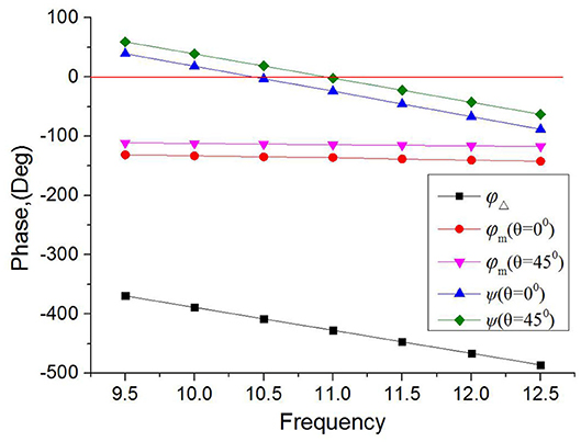
Figure 5. The path difference φΔ, the reflection phase φm of the metasurface and the total phase difference Ψ at different frequencies.
In order to verify the correctness of the antenna design method in the previous section, much research has been carried out and the experimental results show that when the cutting shape is fan-shaped, the bandwidth for circularly polarized has been greatly expanded. Photographs of antennas and test systems are shown in Figure 6.
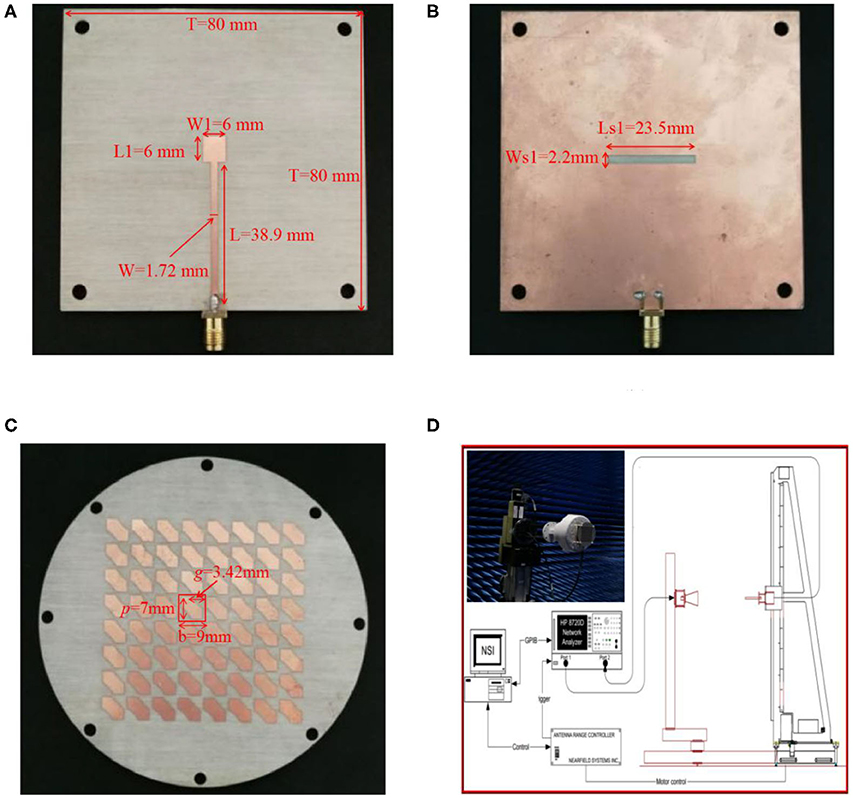
Figure 6. Photograph of the designed antenna and Antenna test system. (A) feeder line of slot antenna. (B) surface of slot antenna. (C) surface of MS. (D) antenna measurement setup.
The antenna is designed on RO4003C substrate with εr=3.55, 32 mil thickness. As shown in Figure 5, the optimized dimensions of the antenna are T = 80 mm, ho = 16.2 mm W1 = 6 mm, L1 = 6.7 mm, W = 1.72 mm, L = 38.9 mm, Ws1 = 2.2 mm, Ls1 = 23.5 mm, Ls = 41.1 mm, p = 7 mm, g = 3.42 mm, b = 9 mm. The simulated and measured S11 of the designed antenna with different rotation angles are shown in Figure 7. The measured results are in good agreement with the simulated results.
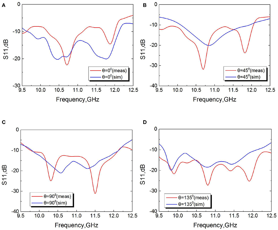
Figure 7. Measured and simulated reflection coefficient S11 with different rotation angle. (A) θ = 0°. (B) θ = 45°. (C) θ = 90°. (D) θ = 135°.
The simulated and measured AR of the designed antenna with different rotation angle θ is shown in Figure 8. The measured 3 dB AR bandwidth is 10–12 GHz (relative bandwidth 18.18%) for the rotation angle θ = 0° and θ = 90°. The simulated and measured radiation patterns and gains of the proposed antenna at 11 GHz are illustrated in Figure 9. The measurements of the antenna pattern are only performed around the main beam for achieving more accurate test results. The measured maximum gain of the designed antenna is more than 14 dBi, when θ = 0°, θ = 45°, θ = 90°, and θ = 135°. The maximum peak is 14.6 dBi at 11 GHz, when θ = 0°. Figure 10 shows the gain of the slot antenna and the gain of the reorganizable antenna. The gain of slot antenna is about 6–7 dBi. When the MS is placed atop the slot antenna, the gain of the antenna is obviously increased. The value of the gain increases by about 7 dBi on average.
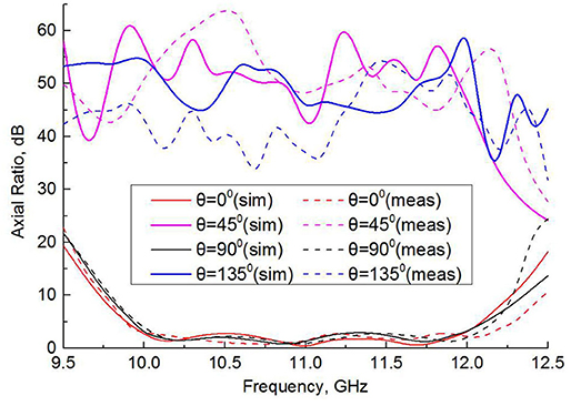
Figure 8. Measured and simulated axial ratio with different rotation angle.
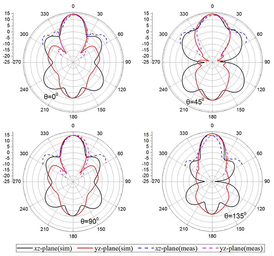
Figure 9. Measured and simulated radiation patterns and gains with different rotation angle at 11 GHz.
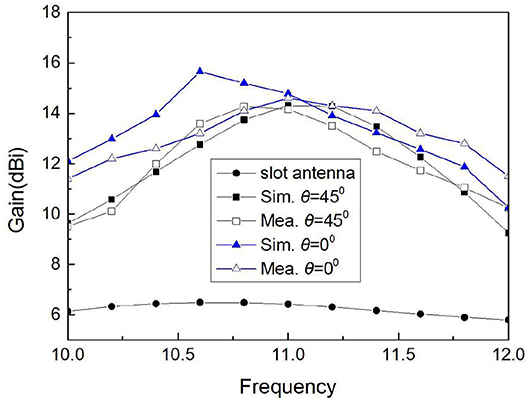
Figure 10. Measured and simulated peak gains vs. frequency with different rotation angle.
The comparison between our work and some published polarization reconfigurable antennas is illustrated in Table 1. This work shows wider bandwidth and higher gain performance. The design method presented in this paper has proved that MS can be used to improve antenna performance more effectively.
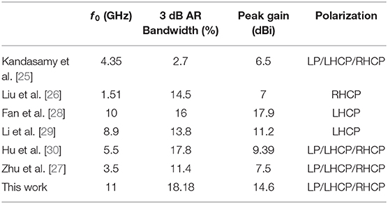
Table 1. Comparison of some published polarization reconfigurable antennas and our work.
A broadband high gain polarization reconfigurable antenna based on MS has been presented. The antenna is composed of a planar MS and a slot antenna. The proposed antenna can be reconfigured to LHCP, RHCP and LP by adjusting the relative position between the MS and the slot antenna. The antenna is studied and designed to operate at around 11 GHz. The S11, AR, radiation patterns and gain of the antenna are measured. The measured results show that the maximum gain of the proposed antenna is 14.6 dBi and that the 3 dB AR bandwidth is 10–12 GHz with state-of-the-art measured performance.
All datasets generated for this study are included in the article/supplementary material.
CN developed the concept and supervised the whole project. CL carried out the simulations and designed the structure and fabricated the sample. CN and CL analyzed the simulation data and contributed to writing and finalizing the paper. ZZ and LZ performed the experiments. MC contributed to paper revision and language editing. All authors contributed to the article and approved the submitted version.
This work was supported in part by Key Natural Science Projects in Education Commission of Anhui Province (grant KJ2020A0105), in part by the Project of Anhui Province Key Laboratory (grant 2019ZDSYSZY02), in part by the National Natural Science Foundation of China (grant 51477039), and in part by the Science and Technology Project of Anhui Province (1708085QF150).
The authors declare that the research was conducted in the absence of any commercial or financial relationships that could be construed as a potential conflict of interest.
1. Huang Y, Yang L, Li J, Wang Y, Wen G. Polarization conversion of metasurface for the application of wide band low-profile circular polarization slot antenna. Appl Phys Lett. (2016) 109:054101. doi: 10.1063/1.4960198
2. Peng L, Wen BJ, Li XF, Jiang X, Li SM. CPW fed UWB antenna by EBGs with wide rectangular notched-band. IEEE Access. (2017) 4:9545–52. doi: 10.1109/ACCESS.2016.2646338
3. Jimenez-Guzman GA, Tirado-Mendez JA, Jardon-Aguilar H. Three-layered circular patch antennas array with UC-PBG for wider bandwidth and surface wave propagation mode attenuation at X-band. Microw Opt Technol Lett. (2018) 60:2676–83. doi: 10.1002/mop.31467
4. Liao WJ, Zhang WY, Hou YC, Chen ST, Kuo CY, Chou M. An FSS-integrated low-RCS radome design. IEEE Antennas Wireless Propag Lett. (2019) 18:2076–80. doi: 10.1109/LAWP.2019.2937556
5. Li JF, Wu DL, Zhang G, Wu YJ, Mao CX. A left/right-handed dual circularly-polarized antenna with duplexing and filtering performance. IEEE Access. (2019) 7:35431–7. doi: 10.1109/ACCESS.2019.2904189
6. Wan X, Zhang L, Jia SL, Yin JY, Cui TJ. Horn antenna with reconfigurable beam-refraction and polarization based on anisotropic huygens metasurface. IEEE Trans Antennas Propag. (2017) 65:4427–34. doi: 10.1109/TAP.2017.2722829
7. Wu J, Zhang ZX, Ren XG, Huang ZX, Wu XL. A broadband electronically mode-reconfigurable orbital angular momentum metasurface antenna. IEEE Antennas Wireless Propag Lett. (2019) 18:1482–86. doi: 10.1109/LAWP.2019.2920695
8. Yu J, Jiang W, Gong SX. Low-RCS beam-steering antenna based on reconfigurable phase gradient metasurface. IEEE Antennas Wireless Propag Lett. (2019) 18:2016–20. doi: 10.1109/LAWP.2019.2936300
9. Tian JY, Li Q, Lu J, Qiu M. Reconfigurable all-dielectric antenna-based metasurface driven by multipolar resonances. Opt Exp. (2018) 26:23918–25. doi: 10.1364/OE.26.023918
10. Chaimool S, Hongnara T, Rakluea C, Akkaraekthalin P, Zhao Y. Design of a PIN diode-based reconfigurable metasurface antenna for beam switching applications. Int J Antennas Propag. (2019) 2019:7216324. doi: 10.1155/2019/7216324
11. Zhu HL, Liu XH, Cheung SW, Yuk TI. Frequency-reconfigurable antenna using metasurface. IEEE Trans Antennas Propag. (2014) 62:80–5. doi: 10.1109/TAP.2013.2288112
12. Darvazehban A, Rezaeieh SA, Zamani A, Abbosh AM. Pattern reconfigurable metasurface antenna for electromagnetic torso imaging. IEEE Trans Antennas Propag. (2019) 67:5453–62. doi: 10.1109/TAP.2019.2916576
13. Ni C, Chen MS, Zhang ZX, Wu XL. Design of frequency-and polarization-reconfigurable antenna based on the polarization conversion metasurface. IEEE Antennas Wireless Propag Lett. (2018) 17:78–81. doi: 10.1109/LAWP.2017.2775444
14. Lian RN, Tang ZY, Yin YZ. Design of a broadband polarization-reconfigurable fabry-perot resonator antenna. IEEE Antennas Wireless Propag Lett. (2018) 17:122–25. doi: 10.1109/LAWP.2017.2777502
15. Wang HF, Wang ZB, Cheng Y, Zhang YR. Dual-polarized lens antenna based on multimode metasurfaces. Chinese Phys B. (2018) 27:118401. doi: 10.1088/1674-1056/27/11/118401
16. Chen SL, Karmokar DK, Qin PY, Ziolkowski RW, Guo YJ. Polarization-reconfigurable leaky-wave antenna with continuous beam scanning through broadside. IEEE Trans Antennas Propag. (2020) 68:121–33. doi: 10.1109/TAP.2019.2935122
17. Wu HF, Wei YH, Chen TR, Row JS. Quad-polarization reconfigurable antenna with wideband operation. Microw Opt Technol Lett. (2019) 61:2080–7. doi: 10.1002/mop.31865
18. Bronckers LA, Roc'h A, Smolders AB. A new design method for frequency- reconfigurable antennas using multiple tuning components. IEEE Trans Antennas Propag. (2019) 67:7285–95. doi: 10.1109/TAP.2019.2930204
19. Asghari A, Azadi-Tinat N, Oraizi H, Ghalibafan J. Wideband frequency-reconfigurable antenna for airborne applications. Wireless Pers Commun. (2019) 109:1529–40. doi: 10.1007/s11277-019-06625-2
20. Iqbal A, Smida A, Abdulrazak LF, Saraereh OA, Mallat NK, Elfergani I, et al. Low-profile frequency reconfigurable antenna for heterogeneous wireless systems. Electron. (2019) 8:976. doi: 10.3390/electronics8090976
21. Liu F, Cheng X, Zhang F, Chen Y, Song HL, Huang YG, et al. Design and assembly of reconfigurable 3D radio-frequency antennas based on mechanically triggered switches. Adv Electron Mater. (2019) 5:1900256. doi: 10.1002/aelm.201900256
22. Zhu HL, Cheung SW, Yuk TI. Mechanically pattern reconfigurable antenna using metasurface. IET Microw Antennas Propag. (2015) 9:1331–6. doi: 10.1049/iet-map.2014.0676
23. Holloway CL, Kuester EF, Gordon JA, O'Hara J, Booth J, Smith DR. An overview of the theory and applications of metasurfaces: the two-dimensional equivalents of metamaterials. IEEE Antennas Propag Mag. (2012) 54:10–35. doi: 10.1109/MAP.2012.6230714
24. Chen XF, Zhao YJ. Dual-band polarization and frequency reconfigurable antenna using double layer metasurface. AEU Int J Electron C. (2018) 95:82–7. doi: 10.1016/j.aeue.2018.08.001
25. Kandasamy K, Majumder B, Mukherjee J, Ray KP. Low RCS and polarization reconfigurable antenna using cross-slot-based metasurface. IEEE Antennas Wireless Propag Lett. (2015) 14:1638–41. doi: 10.1109/LAWP.2015.2415585
26. Liu SH, Yang DQ, Pan T. A low-profile circularly polarized metasurface antenna with wide axial-ratio beamwidth. IEEE Antennas Wireless Propag Lett. (2019) 18:1438–42. doi: 10.1109/LAWP.2019.2938873
28. Fan Y, Wang JF, Li YF, Zhang JQ, Han YJ, Qu SB. Low-RCS and high-gain circularly polarized metasurface antenna. IEEE Trans Antennas Propag. (2019) 67:7197–203. doi: 10.1109/TAP.2019.2920355
29. Li K, Liu Y, Jia YT, Guo YJ. A circularly polarized high-gain antenna with low RCS over a wideband using chessboard polarization conversion metasurfaces. IEEE Trans Antennas Propag. (2017) 67:4288–92. doi: 10.1109/TAP.2017.2710231
30. Hu J, Luo GQ, Hao ZC. A wideband quad-polarization reconfigurable metasurface antenna. IEEE Access. (2018) 6:6130–7. doi: 10.1109/ACCESS.2017.2766231
Keywords: metasurface, polarization reconfiguration, Fabry-Perot cavity, high gain, slot antenna
Citation: Ni C, Liu C, Zhang Z, Chen M, Zhang L and Wu X (2020) Design of Broadband High Gain Polarization Reconfigurable Fabry-Perot Cavity Antenna Using Metasurface. Front. Phys. 8:316. doi: 10.3389/fphy.2020.00316
Received: 03 February 2020; Accepted: 10 July 2020;
Published: 21 August 2020.
Edited by:
Wei E. I. Sha, Zhejiang University, ChinaReviewed by:
Nobuhiko Yokoshi, Osaka Prefecture University, JapanCopyright © 2020 Ni, Liu, Zhang, Chen, Zhang and Wu. This is an open-access article distributed under the terms of the Creative Commons Attribution License (CC BY). The use, distribution or reproduction in other forums is permitted, provided the original author(s) and the copyright owner(s) are credited and that the original publication in this journal is cited, in accordance with accepted academic practice. No use, distribution or reproduction is permitted which does not comply with these terms.
*Correspondence: Chun Ni, Y2h1bm5pX2hmbnVAc2luYS5jb20=
Disclaimer: All claims expressed in this article are solely those of the authors and do not necessarily represent those of their affiliated organizations, or those of the publisher, the editors and the reviewers. Any product that may be evaluated in this article or claim that may be made by its manufacturer is not guaranteed or endorsed by the publisher.
Research integrity at Frontiers
Learn more about the work of our research integrity team to safeguard the quality of each article we publish.