
95% of researchers rate our articles as excellent or good
Learn more about the work of our research integrity team to safeguard the quality of each article we publish.
Find out more
REVIEW article
Front. Phys. , 25 May 2020
Sec. Soft Matter Physics
Volume 8 - 2020 | https://doi.org/10.3389/fphy.2020.00112
This article is part of the Research Topic Topological Soft Matter View all 10 articles
 Kirsten Harth1,2*
 Ralf Stannarius1
We review the interactions and dynamics of topological defects in liquid crystals (LCs) in quasi-two-dimensional (2D) geometries. Such spatial restrictions can be realized in thin freely suspended smectic C films, in thin sandwich cells filled with nematic LCs, and under specific boundary conditions in LC shells embedded in aqueous solutions. Random defect patterns can be created by thermal quenching of the samples from lower ordered into higher ordered phases. On the other hand, well-defined isolated defect configurations for the study of elementary interaction steps can be prepared by using simple mechanical techniques. Observation by polarizing microscopy is straightforward. Spatial dimensions of the experimental systems as well as time scales are convenient for observation. The continuum theory of LCs is well-developed so that, in addition to the experimental characterization, an analytical or numerical description is feasible. From interactions and dynamic features observed in these LC systems, general conclusions on defect dynamics can be drawn.
Topological defects occur in a wide variety of physical systems, ranging from soft matter [1–6] to quantum systems [7–10], superfluid liquids [11–14], and thin magnetic films [15–17] to cosmology [18–22]. Often, the coarsening of defect patterns that form after symmetry-breaking phase transitions determines the establishment of long-range order in the system. The dynamical properties of such patterns are far from being trivial. A promising concept to find a universal description is to look for general features of defect patterns and their interactions in different systems [20–25]. For that purpose, a system in which universal features of defects can be studied relatively easily and in a quantitative way is of great advantage. Some liquid crystal (LC) phases are promising candidates by virtue of their easy handling, straightforward observation, convenient relaxation time scales, and diversity of structures. They allow for studying defect interactions and coarsening dynamics of topological defect patterns with conventional optical polarizing microscopy. Ensembles of very different kinds of defects in LC phases have been described (e.g., [1–5, 26–33]). The observation of pattern coarsening by mutual annihilations of topological point defects in such systems allows for the direct study of “scaling solutions,” providing models for the evolution of monopoles, multipoles, and textures. Isolated defect pairs can be created to study their mutual interactions as the elementary steps of pattern coarsening. Beyond such defect interactions, mixed structures of defects and inclusions of various shapes and sizes or influences of container boundaries can add further levels of complexity. It is possible to add a mass (of attached inclusions) to defects, to set spatial restrictions, and to exploit defects for structural stabilization of two-dimensional or three-dimensional colloids.
A considerable simplification for the analysis of basic features of defect dynamics is the restriction to quasi-two-dimensional (2D) systems, i.e., samples in which the extension in the third dimension is negligible with respect to the typical defect distances and core sizes and samples that can be considered uniform in the third dimension. We focus here on defects in this category of 2D systems, even though this excludes the rich variety of three-dimensional defect structures found in colloidal systems with nematic hosts in flat cells [3, 4, 34, 35] or other geometrical restrictions [36–39]. We also disregard dislocations, which are 3D defect structures formed by smectic phases, but restrict ourselves to disclinations. Finally, we have limited this review to conventional, “passive” LC materials and disregard active nematics (e.g., [41, 42]). The focus of this review is on smectic LCs in thin-film geometry, but we also discuss some quasi-2D nematic systems in sandwich cells, where the character of the director field is sufficiently 2D. Examples of optical images of topological defects in LC films are seen in Figure 1. Topologically, they are classified by the defect strength or topological charge S, which is equal to the number of full rotations of the liquid-crystal director on a closed path around the defect core. Defects of a given strength S may be further distinguished by a phase θ1 (Figure 2). An advantage of smectic freely suspended films over nematics is that experiments with nematics in sandwich cells are not easy to interpret because of the three-dimensionality of the geometric problem. Defects, even if they are well-localized in the cell midplane, usually extend from one glass plate to the other. Interactions with the boundaries, such as pinning, and a preferential alignment or 3D director field distortions near the cell walls have to be taken into account. No-slip boundary conditions for material flow will make the dynamics much more complex than in freely suspended films, for which we can neglect coupling to a surrounding fluid in most cases. The same applies if the defects are located at a confining boundary; their geometry will, in this case, be more 3D in nature. Smectic C mesogens, on the other hand, can form stable, quasi-two-dimensional (2D) freely suspended films (FSFs) similar to soap films when they are stretched across a solid frame [45]. Since their first detailed description by Young et al. [46], they have proven very useful in manifold investigations. Stable films can be as thin as two molecular layers.
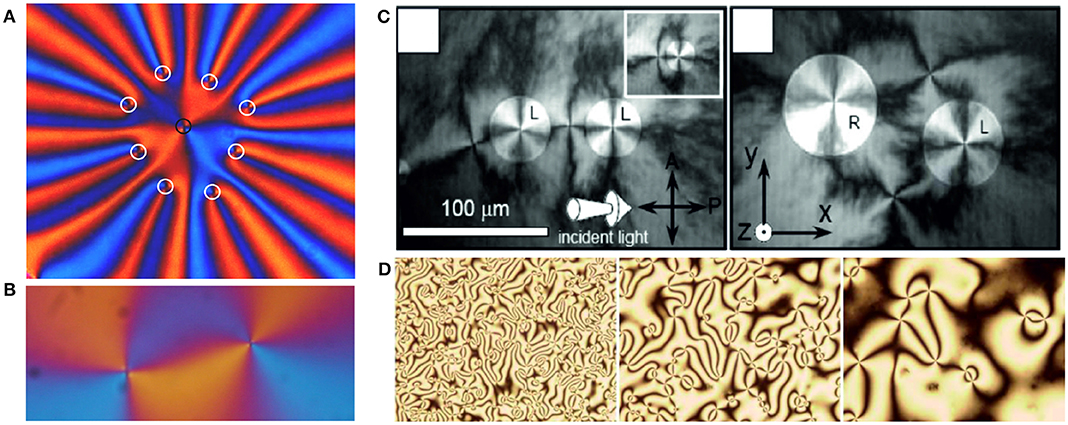
Figure 1. (A) Snapshot of a non-equilibrium arrangement of nine defects in a SmC freely suspended film, all with topological strength +1. The defects repel each other, and the pattern rapidly expands, with eight defects moving radially outward and one remaining in the center. The defect cores are labeled by small circles (see text). Figure adapted from Stannarius and Harth [32]. (B) Pair of two defects of opposite topological strengths, −1 (left) and +1 (right) in a SmC freely suspended film. The defects attract each other and finally annihilate, leaving a defect-free uniform texture. Figure adapted from Missaoui et al. [43]. Both images were recorded with crossed polarizers and a diagonally inserted wave plate. (C) Depolarized reflected microscope images of islands in a SmC freely suspended film. The islands contain tangential clockwise (L) and counterclockwise (R) c-director fields and central +1 defects, each island has an accompanying outer −1 defect. Reproduced from Silvestre et al. [29] with permission, copyright American Physical Society. (D) Coarsening of umbilical defect patterns in a nematic cell with homeotropic anchoring and an electric field normal to the cell plane. The director of the material with negative Δε is driven into the cell plane, forming numerous umbilic ±1 disclinations. Reproduced with permission from Dierking et al. [44], copyright American Physical Society.
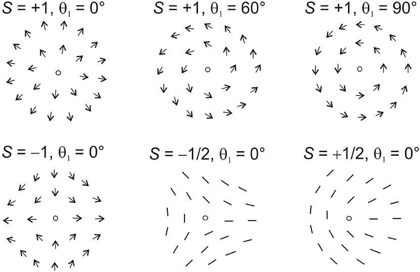
Figure 2. Sketches of topological defects with strengths ±1 and ±1/2 with different phases θ1. The phase of +1 defects changes their structure qualitatively (see top row images), left: “radial,” right: “tangential” configuration. For all defects of strengths S ≠ 1, a non-zero phase θ1 is equivalent to a simple rotation of the defect by an angle θ1/(1−S). The half-integer defects are prohibited in vector fields such as the director field of smectic C phases.
Since there are excellent textbooks that describe the physics of liquid crystals, we recollect here only a few basic features that are necessary to understand the nature, structure and dynamics of defects in LC phases. For a deeper introduction into the properties and theoretical description of LCs, the reader is referred to standard books (e.g., [47, 48]).
The relevant thermotropic LC phases in the context of this review are nematic (N), smectic C (SmC), and smectic C* (SmC*) liquid crystals. Nematics have a molecular arrangement without long-range positional order, and the local preferential orientation of the molecular long axes (the optical axis) is characterized by the director field . Conventional nematic phases are non-polar, belong to the symmetry group D∞h, and the directions and are equivalent. The ground state of a conventional non-chiral, infinitely extended nematic sample is a spatially uniform alignment of . Spatial distortions of the director lead to contributions to the elastic free energy density w in the form
with the elastic constants for splay, K11, twist, K22, and bend, K33, of the order of a few pN. Such distortions can be caused, for example, by the boundary conditions in finite samples, by the existence of topological defects, by application of electromagnetic fields, or by shear flow.
At solid or liquid boundaries, or at free surfaces, the director may adopt preferential orientations. Those are described by boundary conditions, which may be strong (analogous to Dirichlet type boundary conditions), fixing the orientation of the director, or weak (analogous to Robin boundary conditions), fixing a certain relation between the director and its spatial derivatives. For weak anchoring, the director can deviate from its preferred orientation at the cost of an increased elastic energy.
Additional terms may occur in chiral or polar phases. Another term with the saddle-splay elastic constant K24 can be transformed into a surface integral of the free energy, it is thus only dependent on the director orientation at boundaries and can be neglected when the director is rigidly anchored. It may play a role in the vicinity of defect cores. Except near singular points of this director field, one can assume that . In 2D geometry, with , the free energy density equation reduces to
In one-constant approximation, where the elastic constants are set equal to K11 = K33 = K,
and the minimum of the free energy can be found from the solutions of the Laplace equation Δθ = 0. Singular points of the director field mark defects. In their vicinity, the nematic order parameter goes down and the continuum model requires the introduction of a tensor order parameter [49–53]. We will not consider the nanoscopic structure of the defect cores here. In many situations, it is practical to make the reasonable approximation that the director is pinned at the boundary of a circle with radius rc around the defect core, and the actual core region is omitted.
Another important property of nematics is their electric and magnetic anisotropy. In the simplest case of uniaxial nematics, the dielectric permittivity adopts the form
In the case Δε = ε∥ − ε⊥ > 0, the electric torque drives the director toward a parallel or antiparallel orientation respective to the electric field; in the opposite case, the director is pushed toward a perpendicular orientation. Similarly, the diamagnetic susceptibility is a tensor that governs the reorientation of the director in an external magnetic field. Finally, the uniaxial nematic phase is birefringent, with different ordinary and extraordinary refractive indices. This allows optical studies with polarizing microscopy (see section 2.3 below).
Thin SmC films can be treated with the same concept, where a unit vector along the projection of onto the film plane takes over the role of the nematic director. This is appropriate as long as the director orientation is uniform along the film normal, which is fulfilled in micrometer or sub-micrometer thin SmC films and in SmC* films that are much thinner than their helical pitch. We now consider the projection of onto the film plane, with variable length depending on the tilt angle β (see Figure 3). The free energy expansion in the film is [54, 55]
where the Landau parameters A < 0 and C > 0 set the equilibrium length of , viz. the equilibrium tilt angle of respective to the layer normal. Their magnitude describes the resistance against changes of β. At non-zero tilt, one can define a unit vector , the c-director (Figure 3), which is a true vector 1. Approaching the core of a defect in the c-director field, drops to zero, i.e., the material in the core is locally in the smectic A (SmA) phase (β → 0). Note that there are only splay and bend of in the 2D system. With the new constants , , and one obtains
This free energy density is similar to Equation (2). In one-constant approximation, KS = KB = K, the SmC free energy density has the same form as in the nematic case (Equation 3).
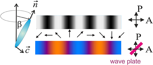
Figure 3. C-director and optical appearance when the planar film is observed with crossed polarizers (top) and with crossed polarizers and diagonally inserted phase plate (bottom).
The conventional geometry to study nematics is that of thin sandwich cells, with cell gaps between few μm and several hundred μm. The director can be anchored homeotropically at both cell plates, or planarly at one plate, homeotropically at the other (hybrid anchoring), or anchored planarly at both plates. The planar anchoring can have a preferential direction in the plane, or it can be azimuthally degenerate. Two examples are depicted in Figure 4A.
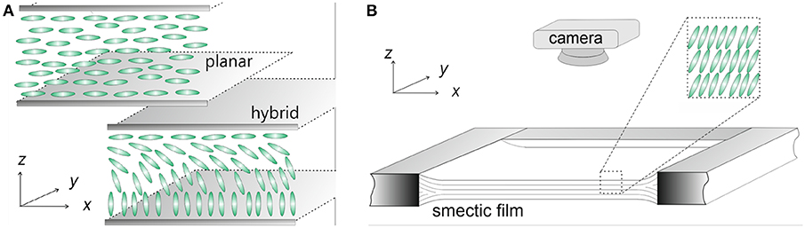
Figure 4. (A) Geometry of nematic cells with planar (top) and hybrid (bottom) anchoring. The mesogens are sketched as ellipsoids. (B) Geometry of a planar freely suspended SmC film in air. The front edge of the solid film support has been omitted for visualization of the layered film structure.
There are various methods to produce defects in nematic cells. The easiest one is a rapid phase transition from the isotropic into the nematic phase across the clearing point, either by a temperature quench or by application of high pressure to trigger this transition [20, 21]. It is advantageous in such experiments to have either homeotropic anchoring conditions at the cell plates (director normal to the surfaces) or planar, azimuthally degenerate anchoring. A rich pattern of string defects occurs after the disorder–order transition. These are three-dimensional and of complex geometry. The problem in this experiment is to achieve a well-defined temperature quench. In Chuang's studies [20, 21], no particular surface treatment was reported. Pargellis et al. [56] improved the experiment by well-defined surface treatment of the sapphire windows to ensure homeotropic boundary conditions of the director in the nematic phase. The temperature was quenched by cooling one of the plates below the clearing point and keeping the second one above that point so that a phase boundary between isotropic and nematic states was established and kept in the middle between the cell plates. After this temperature quench, the director adopted degenerate planar boundary conditions at the nematic-isotropic (N-I) interface. Defects that form spontaneously in the nematic move to the N-I interface. Owing to broken mirror symmetry of the anchoring conditions on both interfaces, the 3D director field includes tilt, and only integer-strength defects can form.
This experimental technique was further improved by Nagaya et al. [57, 58] and later employed by Dierking et al. [44, 59]. Their experiments were performed under isothermal conditions in a homeotropic cell within the nematic phase. The authors used materials with negative dielectric anisotropy Δε = ε∥ − ε⊥ < 0 and applied an electric field along the cell normal. The director remained anchored homeotropically at the cell plates but was driven out of the field direction in the cell center. The maximum director deflection toward the planar orientation was then in the cell midplane. It was not necessary to fix temperature gradients in a sophisticated way to keep the phase boundary in the cell center as in Pargellis et al. [56]. The geometry of the umbilics that form was such that only integer-strength disclinations were possible (Figure 1D). We note that umbilics are, strictly speaking, not defects because they do not contain singularities of the director field. In a 2D projection, however, they behave in many respects like point defects and show similar interactions.
In all these types of nematic sandwich cells, one has to consider the peculiar boundary conditions for the nematic at the glass plates. The director field is therefore in general three-dimensional. Not only is the director anchored at the plates, but the flow field also has 3D character because of its no-slip boundary conditions. Even though many studies of defect dynamics have been performed in nematic cells (e.g., [20, 21, 44, 59–67]), these limitations must be clearly recognized [62, 68, 69]. A different geometry for nematics is that of spherical shells of few μm thickness and diameters of the order of 100 μm, which are filled with, and suspended in, surfactant solutions [40, 70]. There, one can adjust planar, degenerate, or hybrid boundary conditions to create defect structures of the director field. The spherical geometry requires a total topological charge of +2 in the director field at any surface with planar components of . The closed nature of the nematic layer imposes special restrictions to the arrangements of topological defects [71–77]. In smectic shells with homeotropic anchoring, layers arrange in an onion-like structure. The layer arrangement is usually more complex for hybrid or planar anchoring of [40, 73]. This special geometry of LC shells will not be considered in the following because of its many peculiarities that are unrelated to defect behavior in the flat 2D geometry.
Smectic C phases offer several advantages over nematics when one is interested in a quantitative determination of defect interactions, dynamics, and annihilation processes. These materials can form FSFs with huge aspect rations, either as planar films (Figure 4B) or bubbles. These films are ideal model systems to study defect dynamics: they can be prepared with thicknesses that are uniform on a molecular scale. The local orientation is well-described by a continuum theory of a 2D unit vector field . Film thicknesses are between a few nanometers and several micrometers depending on the preparation conditions. Since all relevant forces scale linearly with the film thickness, the dynamics of the point disclinations are independent of film thickness as long as air drag can be neglected. Lateral widths of the films can be chosen in the millimeter and centimeter ranges so that influences of the boundaries on the local defect dynamics can be controlled. Spatial dimensions of defect patterns in the micrometer range and time scales of annihilation experiments of few seconds offer convenient observation conditions.
The spatially uniform alignment of the c-director is the ground state. Boundary conditions at the film holder may impose certain c-director distortions or even require the necessity of a defect in the film. If the film is disturbed, e.g., by quenching it into a lower symmetry phase [78–81], by a sudden air blow causing complex shear flow patterns in the film plane [82–84], or by rapid changes of the film geometry in presence of inhomogeneous director fields [32, 43, 85], point disclinations can be generated.
Pargellis et al. [78] performed experiments in SmC FSF. Defects were created by temperature quenches from SmA into SmC. Some of the disadvantages of this technique are difficulties to avoid spatial temperature inhomogeneities during the quench, which may evoke Marangoni effects, and advection of the film with airflow. In order to avoid these complications, Muzny [80] studied defects produced with a mechanically induced phase transition from SmA to SmC. Films were spanned across a circular frame and could be deflected by an overpressure of a few Pascal to SmC sphere caps. Upon sudden release of the overpressure, the caps collapsed to flat films, thereby reducing their surface. The consequence was a rapid transition from SmC to the SmA phase. Upon reducing the mesogen tilt angle β very quickly to zero, the film thickened and partially compensated for surface area reductions. Within few milliseconds after collapse, the SmC phase was re-established, and a c-director texture with multiple defects appeared. Wachs [81] performed similar experiments with the same technique in very thin (two-layer) SmC films.
An alternative is the preparation of islands (circular thicker film regions), which can be achieved by air flushes [84] or by a reduction of the film area of very thin films [86, 87]. Since the c-director is anchored at the island borders, each island necessarily contains a +1 defect in equilibrium. A compensating −1 defect is formed in the film surrounding the island. Defects can also form spontaneously, starting from a periodically distorted director structure in film menisci [88–91]. Such defects can migrate into a uniform film region (see Figure 5A). Multiple +1 defects can be pinned in small thinner regions (“holes”) of an otherwise uniform film [32], as in Figures 5B,C.
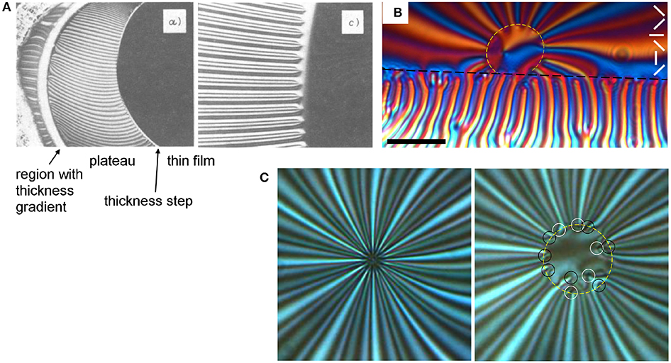
Figure 5. Arrays of +1 point defects pinned at layer steps of free-standing SmC films: (A) A continuous director distortion extends from a stripe pattern in a band of decreasing thickness (white arc in a), connected to the meniscus at the film holder, across a plateau of homogeneous thickness (striped region in the middle of a), and ending in several +1 point defects at a thickness step toward the thinner film seen in black on the right. The region near the stripe ends is enlarged in (c). Image size of (c) 455 × 367 μm2. Figure reproduced from Maclennan [88], copyright IOP Publishing. (B) Defects trapped around a circular film thickness step (yellow dashes), with its connection to the meniscus (below the black dashed line). Crossed polarizers parallel to the edges, with wave plate at 45°, scale bar 50 μm. Adapted from Harth [91]. (C) Stripe array with 12 trapped +1 defects in the central region, left: in equilibrium (the thinner region enclosed by the film thickness step is not resolved); right: after the film is slightly expanded, the 12 individual defects are visible. Because of KS > KB, they are all tangential. Black and white circles mark +1 with opposite sense of rotation of , yellow dashes indicate the main layer step trapping the defects. Crossed polarizers parallel to the edges, image dimensions 72 × 72 μm2. Microscopy images taken from Stannarius and Harth [32], copyright American Physical Society, annotations from Harth [91].
A simple technique to produce defect pairs is to touch the films with a thin fiber [43]. At the contact spot, the fiber circumference may enforce a preferential tangential or radial anchoring of the c-director and a compensating nearby −1 defect. If one moves the fiber far enough away from the latter defect before the film is released, a conjugated pair remains.
A very peculiar exception are materials that exhibit a sign change of one of the elastic constants, for example, the bend elastic constant. In such a material, the uniform ground state is no longer energetically favored, a film with uniform texture will spontaneously develop defect pairs connected by inversion walls [93]. A similar spontaneous formation of defects in a uniform film was described by Dolganov et al. [94] and attributed to a spontaneous bend term in a chiral smectic C* material.
The optical anisotropy in the film plane is determined by the orientation of the c-director, which reflects the tilt azimuth. This allows optical observation of the c-director field by means of polarizing microscopy in transmission or reflection. Figure 3 sketches the c-director and the optical appearance of a SmC film when observed with crossed polarizers (top), or crossed polarizers and a diagonal λ wave plate (bottom). Without the phase plate, the texture is fourfold degenerate, and with the phase plate it is two-fold.
The c-director field is extracted from transmission images under crossed polarizers as in Figure 5C, or with an additional diagonally inserted full wave plate (550 nm, slow axis from top right to bottom left), as in the examples shown in Figures 1A,B, 5B. With the phase plate, the films appear bluish where the c-director is diagonal bottom-left to top-right or vice versa, and they appear orange where the c-director is oriented diagonal from bottom-right to top-left or vice versa. It is impossible to distinguish the directions and at normal incidence. When the c-director field corresponding to a certain texture is plotted in the following, the sense of direction of was chosen arbitrarily in each experiment. This is no problem as long as this selection is consistently maintained within each experiment, because the free energy, force, and torque equations do not depend upon the sign of . An alternative is Depolarized Reflected Light Microscopy (DRLM), with the same limitations (see images in Figure 1C).
In nematic cells, the situation is in principle similar, but the director is usually not uniform along the cell normal. The optical axis may thus have spatially varying polar and azimuthal angles. The optical intensity in transmission depends in a more complex fashion on . In a crude approximation, one may usually presuppose that textures under crossed polarizers reflect the orientation of the in-plane components of . This is fulfilled when the director field is uniform along the cell normal.
Then, textures and defects have appearances very similar to those of the c-director given in Figure 3, with the c-director replaced by the director projection: Dark regions indicate that the projection of the nematic director onto the cell plane is along one of the polarizers. Bright regions reflect diagonal projections. If is perpendicular to the cell plane everywhere, the texture under crossed polarizers is uniformly black.
A more elaborate analysis reveals that the transmitted intensity does not only vary with the phase lag between ordinary and extraordinary wave in the cell and the polarizer orientations. One also has to take into account that in-plane variations of modulate the spatial refractive index profile. In contrast to thin smectic films, this may generate refraction and intensity modulations of transmitted light even in absence of polarizers so that defects may be visible even in unpolarized light.
Continuum models of the nematic and smectic C phases form the theoretical basis of the description of defect dynamics. The simplest assumption made in many models is that the motion of the defects is overdamped and adiabatic. There is no inertia related to the director reorientation or defect core motion. Defects move with a velocity determined by the balance of elastic forces that arise from the gradients in the potential and counteracting viscous forces caused by director reorientations and possible coupling to flow. Each snapshot of the director field can be assumed to represent a free energy minimum under the condition of fixed defect core positions (sometimes including a given flow field). Such interaction forces can be generated, e.g., by fixed anchoring conditions of the director at a boundary near the defect. In a pair of defects of equal or opposite topological charges, their elastic interaction forces drive mutual attraction or repulsion.
The interaction between two disclinations was first calculated under the simplifying assumption of equal splay and bend elastic constants, i.e., KS = KB = K, in the absence of material flow. The director field is taken as a linear superposition of the single-defect solutions of the director field [95]. For individual defects with topological charge Si positioned at the origin (0, 0), these individual solutions have the form
where φ is the angle between and the x axis, and θi is the phase of the defect. For two defects of topological charges S1 and S2 at positions and , this yields
The two arctan functions yield the angles of the position vectors and with the x axis. This solution is sketched in Figure 6A for S1 = +1 (left), S2 = −1 (right) and θ∞ = −π/2 (the c-director angle in infinity). The problem with this type of solutions is that it produces only defect pairs whose phases match, i.e., the c-director along a straight line connecting the defects is constant, since the arguments of the two arctan functions in Equation (7) remain constant on the straight line connecting the defect cores. This is only a specific subset of the solutions of the general problem, where defects can have any phases.
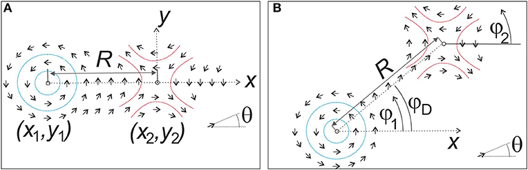
Figure 6. (A) Two defects with matching director fields, i.e., they can be written as a simple superposition of the solutions for two single conjugate defects. (B) Two defects whose phases do not match: the director changes along the straight line connecting the two cores.
For two such specific defects with strengths S1 and S2, separated by a distance R, the mutual attractive or repulsive force per film thickness is [96, 97]
It acts along the separation vector , where are the positions of the two cores. Thus, the two defects are expected to approach or move away from each other on straight paths. In nematics, the defect strengths can have integer or half-integer values. In SmC films, owing to the polar character of the c-director, point defects can only have integer strengths. Disclinations of the same sign repel, those of opposite signs attract each other, with forces inversely proportional to the distance R.
Equations (7), (8) describe defect pairs with “ideal” orientations respective to each other, and with “ideal” orientation of to the far director field. The basic models that led to Equation (7) assume that the superposition of two interacting defects is the only director field deformation present. This is correct only if the orientations “match,” i.e., the θ is constant along the line connecting the two cores, as sketched in Figure 6A. These models cannot describe the effects of mutual orientation mismatches (with regard to the phase angles θ1,2 of both defects) such as those sketched in Figure 6B. In practice, one has to take into account that phases of interacting defects in general do not match. The effects of these mutual orientations were first discussed by Vromans and Giomi [99]. They argued that half-integer defects have a generic orientation (“tilt”), which affects their interactions qualitatively. It changes the trajectories of mutually attracting or repelling pairs so that their motion is no longer along the interconnecting line (Figure 7).
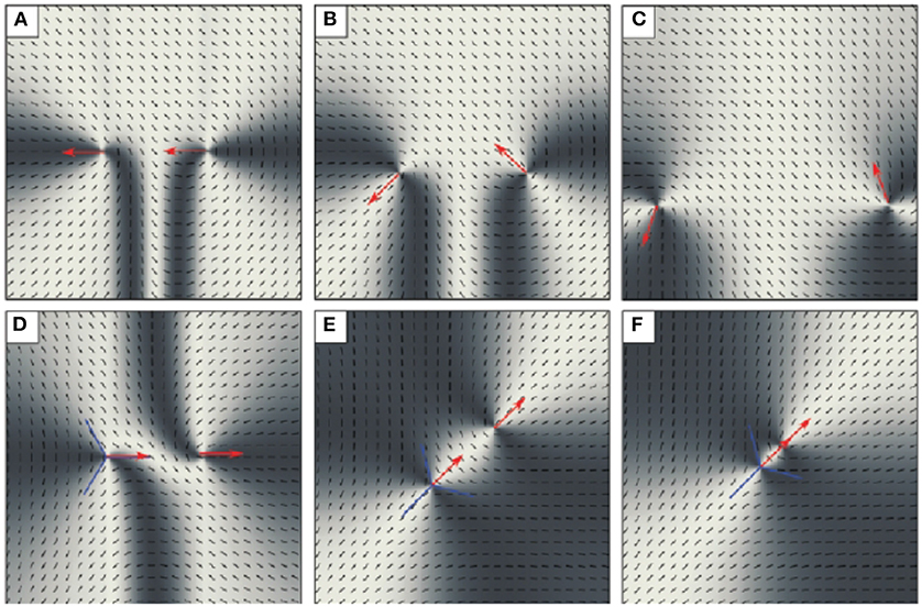
Figure 7. Temporal evolution of a pair of mutually repelling +1/2 defects (A–C) and mutually attracting ±1/2 defects (D–F), simulated with Neumann boundary conditions, and an initial separation of the defects of 1/3 of the computed region. Red arrows indicate the “tilt,” a quantity introduced to describe the defect orientations. Even though the interconnection vector is initially horizontal in the images, the defect trajectories are curved, and the direction of defect motion noticeably differs from that vector. The image was reproduced from Vromans and Giomi [99], with permission of the Royal Society of Chemistry.
Tang and Selinger [100] extended this idea and generalized it to arbitrary defect strengths. They introduced tensors of rank n|1 − S| to characterize the orientation of defects of strength S in n-atic phases (phases with an orientational order parameter of n-fold symmetry). In the non-polar nematic phase, S = +1/2 defects are described by a vector, −1/2 defects by a tensor of rank 3. In polar nematics and SmC, the +1 defect is a scalar, the −1 defect is a tensor of rank 2. Tang and Selinger derived explicit expressions for the director field around defect pairs with different orientations and for the elastic energy depending on the defect orientation parameters. The analytical solutions were found using a conformal mapping technique [100], which works only under the condition of elastic isotropy (KS = KB).
We use their concept to discuss effects of defect orientations on interactions of conjugated pairs, S1 = −S2 = S. The equilibrium solutions are [100]
where the angle φD defines the direction of respective to the x axis (Figure 6B), and rc is the defect core radius. It is assumed that rc is very small compared to R. The director field at circles with radius rc around the cores is described by equations of the form of Equation (6). The terms −Sπ and +Sπ in the definitions of δθ and θ0 arise from the correct choice of the quadrants of the arctan functions used in Tang and Selinger [100]. The first line of Equation (9) plus θ0 reproduces the solution for pairs with mutually matching orientations (Equation 7). The second line with the parameter δθ/2 is a solution of the Laplace equation with fixed boundary conditions θ = 0 at the core of the S1 defect and θ = δθ at the core of the S2 defect.
These equilibrium solutions are exact, but they lead to a boundary condition of the director field at infinity θ∞ = δθ/2 + θ0 = (θ1 + θ2 + Sπ)/2 that depends upon the phase angles of the two defects. This is no problem unless one wants to describe realistic experimental systems where the director far from the conjugated pair is usually homogeneous and independent of the defect positions and orientations. In order to realize such fixed boundary conditions, we rotated the solutions of Equation (9) to fix θ∞. Without loss of generality, we chose [primed angles refer to the rotated system (x′, y′)]. In the primed system rotated by −θ∞, the defect phases become
Some representative solutions are visualized in Figure 8 for ±1 defect pairs and more in Missaoui et al. [43]. In the special case S = 1, the equations simplify to and , the phase angle of the scalar +1 defect is preserved. One can easily verify that gives the correct boundary condition in all cases. The phase mismatch δθ, i.e., the angle by which the director reorients on the straight line connecting the two cores, remains invariant under rotations of the coordinates. It is one of the two essential parameters for the pair orientation. The second important parameter describing the defect pair is the orientation of the connection vector with respect to the far director. We will refer to as the misalignment angle. It becomes
It is useful to introduce the misalignment parameter . The most important result of this analysis is that according to Equation (11), the mismatch δθ and the misalignment δϕ are not independent of each other in equilibrium. The mutual phases of the conjugated defects and the orientation of the defect pair in the external director field are strictly related. Defect pairs in equilibrium adopt a mismatch angle in accordance with their positions in a given external director field.
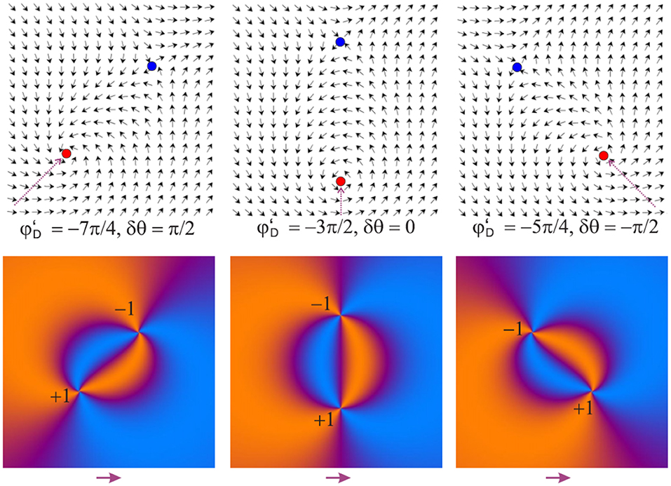
Figure 8. Static director fields around matching and mismatching defect pairs obtained by Equation (9) (top) with δθ = (π/2, 0, −π/2) from left to right in a homogeneous external director field indicated by the pink arrow below the plots. The red dot marks the +1 defect and the blue dot the −1 defect. The bottom row shows their appearance between crossed polarizers with diagonal phase plate. The image was reproduced from Missaoui et al. [43].
The elastic free energy of a film of thickness h, associated with the distorted configurations of a defect pair, is [100]
where the first term represents the usual elastic energy for matching defects with topological charges ±S. The second term is the effect of mismatch, which generates a torque. Again, the equilibrium also fixes , the orientation of the topological dipole in the surrounding director field, thus the rotation of the −1 defect and the orbit of both defects around the annihilation center cannot be separated in this model. At defect separations that are large compared to rc, the torque is
The previous derivation presupposed one-constant approximation. Two aspects have to be considered: Already Chandrasekhar [101] noticed that an elastic anisotropy causes a torque if the predominant elastic deformation between the defects is unfavorable. This holds true even if this pair is aligned and has matching phases. Second, defects with topological charge S = +1 have a peculiarity: the director field in the vicinity of the core can either be pure splay for θ1 = {0, ±π}, or pure bend for θ1 = ±π/2. Since the deformation energy diverges near the core, the director will be pinned there, either radially or tangentially. All other types of defects are less affected by elastic anisotropy. The director field structure slightly changes when KS ≠ KB, but the energy of isolated defects does not depend on their phase angle θi. Because of their symmetry, director fields near the S = +1 defect core are unaffected by elastic anisotropy, but all other types contain splayed and bent regions in their vicinity. Regions related to the smaller elastic constant are compressed, while those related to the larger elastic constant expand to minimize the elastic energy. The director field around an isolated S = −1 defect in presence of an elastic anisotropy α = (KS − KB)/(KS + KB) changes to [102]
with a prefactor q determined by (S − 1)φ[π, q] = −2φ[π, q] = π. We note here that the combination of defect phase match and alignment concepts with elastic anisotropy, with material flow and with finite system size is currently almost unexplored. This requires further theoretical effort. Gartland et al. [98] derived a general energy-based framework to determine the force acting on point defects in nematics. They noted that the static director fields considered above will, in general, not be identical to the dynamic director field configurations during defect annihilation, particularly not in presence of backflow (see next section). Tang and Selinger [103] exemplarily calculated a correction term describing the director field change due to a motion of ±1/2 defects at constant velocity in presence of material flow. Thus, simply deducing the annihilation dynamics from the energy landscapes of static solutions for the director field may not be adequate.
After having obtained the equilibrium director configurations for defect pairs in given distances and orientations, we now discuss their dynamics: It is a widely used concept to assume that interacting defects moving in the LC system pass equilibrium configurations of the director fields in an adiabatic way. The specific drag force (per film thickness) on a defect of topological strength S moving with velocity v in a film at rest is [104]
L is a characteristic system size. Flow is neglected here, the one-constant approximation is used, and γ1 is the rotational viscosity. Pleiner [105] derived an equivalent equation for a defect moving in a SmC film, with γ1 as the rotational viscosity of the c-director. The problem with this equation is its logarithmic divergence with L, which requires setting some long-distance cut-off. Ryskin and Kremenetsky [106] proposed a correction that leads to
with the Ericksen number Er = γ1vrc/K. Note that, since the defect is an immaterial object, it does not involve material transport in this approximation. Thus, shear viscosities do not enter the drag force equation.
The balance of the elastic force Fe and the drag forces Fdrag on both defects yields the velocity
for each defect. According to Equation (17), two disclinations of opposite charge approach each other with velocities essentially inversely proportional to the separating distance R (disregarding the velocity dependence of Er). With Ṙ = 2v, one obtains
where t0 is the annihilation time.
A more accurate model has to incorporate several aspects: first, the approximation that a moving defect has the same director configuration as a defect at rest needs to be checked [107]. Second, the defect velocities are influenced by the elastic anisotropy α = (KS − KB)/(KS + KB) ≠ 0 [6, 55]. Third, backflow effects cannot be neglected in most situations (except in Langmuir films where the subphase effectively inhibits such material transport).
An elastic anisotropy α ≠ 0 will cause a difference in the velocities of the defects of the pair, even when the film material is at rest. Because of their symmetry, +1 defects are unaffected. The altered director configuration around a −1 disclination (Equation 14), however, influences the specific drag force in Equation (15). Brugues et al. [6] obtained for ±1 defects moving with velocity v in a restricted domain with radius Rd
respectively, independent of the direction of motion. This effect was already observed in simulations by Svenšek and Žumer [55]: The +1 defect will move faster toward the annihilation point than the −1 defect, irrespective of the sign of the elastic anisotropy α.
However, the differences in defect velocities caused by elastic anisotropy are small compared to flow-coupling effects in SmC FSFs or effectively 2D nematic films. In particular, as the defects move, coupling between the inhomogeneously changing director field and the velocity field (so-called backflow) plays a significant role. Defects of different strength couple to the flow field in different ways. Using a tensor order parameter description, simulations of Toth et al. [51] showed that, in a 2D nematic, the +1/2 defect moves faster than its −1/2 counterpart.
The coupled problem of director reorientation and flow is described by the Ericksen-Leslie equations, see, for example, Stewart [108] for a comprehensive discussion. These equations have to be treated numerically in general. Few analytical results exist [109–111] regarding the asymmetry of the motion of the defects in a conjugated pair [109, 111] and the qualitative structure of the backflow field [110]. The sign of the velocity field at the defect position depends on the topological charge: the fastest flow occurs in front of the positive defect toward and behind the negative defect away from the partner [110]. Coupling director reorientation and flow can speed up the relaxation significantly and it induces vortices in the flow field accompanying the moving defects, as first predicted by Denniston et al. [52]. The qualitative effect of backflow on the defect velocities is similar for defect lines and umbilics in nematics and point defects in SmC FSFs: while backflow increases the velocity of the positively charged defect, motion of the negative defect is hardly affected by backflow, often even reduced [51, 53, 55, 112, 113]. Due to the structure of the equations, the scaling of the defect separation with time to annihilation is preserved until the defects approach so closely that their core regions start overlapping. Svenšek and Žumer [55] studied the influence of the Ericksen-Leslie viscosities and elastic anisotropy on ±1 defect pair annihilation in a SmC film numerically on a short spatial scale of initial separations.
Qualitative results are summarized in Figure 9B. Compared to the reference case without flow [Figure 9A, graph (a), and Figure 9B, graph (c)], both elastic anisotropy and flow slow down the −1 defect and accelerate the +1 defect. The annihilation points are shifted toward the initial position of the −1 defect. In general, symmetric terms of the stress tensors, e.g., the complete elastic stress tensor in one elastic constant approximation, affect motion of both defects in the same way, thus they do not contribute to an asymmetric annihilation process [55]. The γ1 term in the viscous stress tensor is antisymmetric. It dominates the flow coupling during annihilation: the generated flow carries both defects with the same velocity in the same direction [55]. This enhances flow near the +1 defect while reducing flow near the −1 defect. The efficiency of backflow increases with the ratio of γ1 to the isotropic viscosity α4. The flow driven by the above terms does not depend on the phase θ1 of the +1 defect (Equation 6). The viscosity coefficient γ2 = α2 + α3 becomes relevant when the phase of the +1 defect is varied: a tangential +1 defect annihilates faster than a radial one with its partner (compare curves e and f in Figure 9B). For general phase angles θ1, the induced flow field even breaks the symmetry respective to the axis connecting the defects [53]. The situation is qualitatively the same for annihilating ±1/2 lines in 2D nematics [53]. The coarsening of defect patterns is only slightly accelerated by hydrodynamic effects, and the R(t) scaling behavior is unchanged [114], at least when R ≫ rc. It is also common to 2D nematics and SmC models that initialization of the simulation with an equilibrium director field of given defect positions causes significant transient deviations from the expected scaling behavior [53, 55].
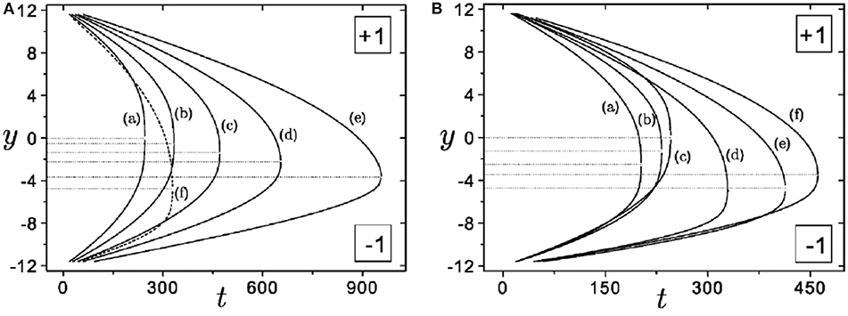
Figure 9. Effect of elastic anisotropy (left) and flow parameters (right) on defect annihilation of a (+1/−1) pair. (A) no flow, (a) α = 0, (b) α = 1/3, (c) α = 3/5, (d) α = 7/9 (e) α = 15/17, (f) same as (d) in right image, for comparison. (B) (a) θ1 = 0, α = 0, (b) θ1 = π/2, α = 0, (c) without flow, α = 0, (d) θ1 = 0, α = 0 with rotational viscosity γ1 doubled, (e) θ1 = 0, α = 2/3, (f) θ1 = π/2, α = −2/3. Images reproduced from Svenšek and Žumer [55], copyright American Physical Society.
An alternative, coarse-grained approach to describe defect dynamics is based on Rayleigh dissipation functions, as outlined by Vertogen [115], Sonnet and Virga [116], and Tang and Selinger [103]. Tang and Selinger [103] recently employed this technique to predict the motion of disclinations, including their reorientation, treating the defects as effective “particles”. The authors considered passive nematics where the drag on ±1/2 disclinations is shown to depend upon the orientation of the defects relative to the surrounding director field (a feature that is closely connected with the mismatch and misalignment angles discussed above). The study describes a coupling of translations and rotations in the defect dynamics. In addition, an extension of the model to active nematics was developed by introduction of an activity coefficient.
The influence of an in-plane aligning electric field on the annihilation of ±1/2 disclinations was described for 2D nematics with weak degenerate planar anchoring [63, 117]. The director distortion in-between the pair is compressed to a wall of relatively constant width along the connecting axis. This leads to a different scaling regime where the energy decreases linearly with decreasing wall length, and the defects approach each other at constant velocity [63]. Speed anisotropy between the defects is caused mainly by backflow and not by elastic anisotropy.
Umbilic distortions in nematics with negative Δε in homeotropically aligned cells with an electric field normal to the cell are in many respects similar to SmC defects. However, in the former, one always has to consider 3D effects due to the finite cell gap, evoked by boundary conditions on the director and flow fields [59]. The dynamics also depend on the electric field strength, which sets the core size of the umbilic structure [59]. When bend is favored to splay in the nematic, the elastic anisotropy speeds up the −1 umbilic [59]. Remarkably, this is opposite to the behavior of ±1/2 disclinations in nematic cells and ±1 disclination pairs in SmC FSFs.
When the elementary process is known, one may draw conclusions from pair annihilations to the coarsening of random patterns with multiple defects. For that purpose, a distribution of defects with a given density ρ(t) per unit area is considered, and its scaling with time is analyzed statistically. In a given film area, ρ ∝ ℓ−2 depends upon some characteristic length ℓ related to the average defect distance. Coarsening proceeds as a sequence of individual annihilation steps of neighboring conjugated strings or point defects. From scaling arguments, considering the energy dissipation rate and the defect energy of a network of string defects in a nematic, a decay of the defect density with ρ(t) ∝ t−1 was predicted [20] in 2D. The typical length scale in such a system increases with t1/2.
A number of 2D experiments were performed in nematic cells under different anchoring conditions (e.g., [20, 21, 44, 56–59, 62, 63, 118, 119]), mainly focused on pair annihilation and on coarsening statistics. Irrespective of the apparent simplicity of the experimental realization, only a few experimental studies have examined point defects and their interactions in smectic C FSFs (e.g., [32, 78–81, 86, 120]) to test the above described theoretical models and predictions. However, there has been considerable work on inclusions in SmC FSFs where self-organization caused by topological interactions has been investigated. We refer the reader to a recent review by Dolganov et al. [33] and to the review by Bohley and Stannarius [121].
Finally, there are a few publications on defects in Langmuir films (e.g., [6, 122]), which share many properties with thin smectic films, viz. their quasi-2D geometry and homogeneity in normal direction. The c-director can rotate freely at the interfaces. On the other hand, the coupling to the subphase inhibits flow. We have grouped the experiments in this section by the arrangement of defects instead of the mesophase in which they are formed.
Structure and dynamics of single disclinations in nematic and smectic phases have been studied by several techniques. While with polarizing microscopy the core structures of conventional nematics are not accessible, transmission electron microscopy (TEM) can visualize such structures after they were frozen quickly into a crystalline state [123–127]. Often, this technique is employed with polymeric liquid crystals where the structure transfer to the solid phase is easier to achieve. Recently, experiments were also reported for chromonic liquid crystals [127]. Since the long-range interactions of defects are hardly affected by the inner core, we have disregarded this aspect in the following section. At greater distances, the director structure can either be determined with polarizing microscopy or by decoration of the distortions with inclusions [26, 128].
In thin SmC films surrounded by a uniform meniscus, topology requires a total topological charge +1 within a flat smectic film. An energetically favorable state is a single +1 defect near the film center. This holds similarly for defects enclosed in smectic islands or holes (Figure 1C).
The +1 disclinations in LCs have a peculiarity: they are invariant to rotations, irrespective of an elastic anisotropy. In case of α ≠ 0, they choose the configuration with lower energy, which in nematics can be either splay or bend depending upon the material parameters K11 and K33. In smectic C, non-polar materials have KB < KS because the bend constant contains contributions from director twist (see line above Equation 5), which are less energy costly. This may be opposite in strongly polar SmC* materials where the spontaneous polarization tends to avoid splay. When this polarization is perpendicular to , it increases the effective bend constant [129]. However, even though radial and tangential configurations represent the equilibrium states, a strong enough torque exerted by the external director field may distort the defect and may even cause the c-director to flip θ1 by ±π at the defect core. For such a jump over the potential wall, a sufficiently strong distortion is needed. This can be realized by spinning the c-director in a circular film with strong anchoring at the outer meniscus by means of electric or magnetic fields [130, 131]. When the field is switched off, the +1 defect that is necessarily present in the film because of the boundary conditions moves to the center. The phase difference between the defect core and the film boundary (seen as a spiral pattern, Figure 10) can only relax if the c-director reorients at the meniscus or at the defect core. The spiral contracts toward the center and increases the torque near the core until the barrier is surmounted and the phase mismatch is relieved by π. Note the strong deformation near the core in the second image of Figure 10, immediately before the flip. In practically all other experimental situations where SmC defect pair or pattern dynamics are considered, such strong distortions are absent; thus the c-director remains pinned tangentially at the +1 core, either clockwise or counterclockwise. In Figures 1A, 5C, the clockwise (CW) and counterclockwise (CCW) tangential defects are marked with black/white circles. Since the sign of cannot be distinguished in reflection microscopy at normal incident light, the assignment is not unequivocal. The black circle may mark a CCW defect and white circles CW defects or vice versa.
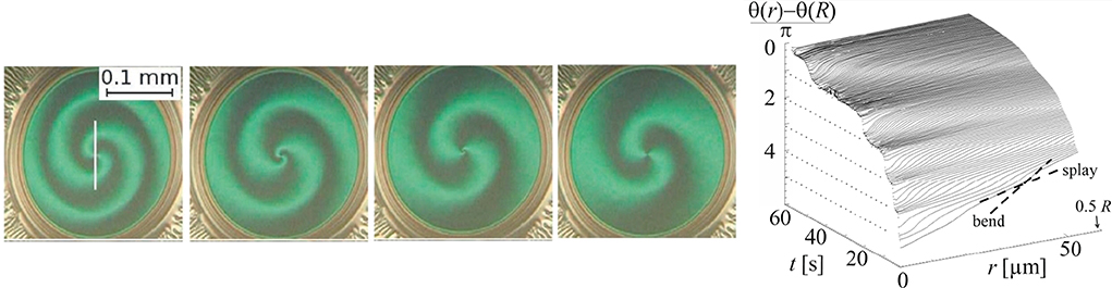
Figure 10. Central +1 defect in a radially distorted director field within a SmC FSF. Images taken during relaxation in 4 s steps. The phase of the defect relative to the film border is initially 2π, it slips to π in the last image. Dark and bright green regions reflect horizontal and vertical c-director orientations, respectively, in these pictures. The relief on the right shows the time dependence of the radial phase profile in the film center. Image adapted from Eremin et al. [131].
The position of disclinations in FSFs is subject to Brownian diffusion in a potential given by the elastic energy landscape which is defined by the boundary conditions. Diffusive motion is counteracted by viscous drag due to director reorientations [79, 80, 105]. A single +1 defect in the center of a circular film shows normal diffusion with a linearly time-dependent mean square displacement (MSD) as long as this displacement is small compared to the film radius. Diffusion coefficients are of the order of 10−11m2/s [80]. At longer times, the confining potential of the film boundaries takes effect, and the MSD saturates. Central defects within islands experience particularly strong confinement. Wachs [81] showed that the diffusion constant for extremely thin films significantly increases under reduced ambient pressure, while the elastic constant remains roughly unaltered. This evidences that the material flow driven by inhomogeneous director reorientations in the film couples to flow of the ambient gas. This coupling mechanism is similar to that of the subphase of Langmuir films, yet the effect is much weaker. Similar film thickness dependent effects on the mobility of inclusions in quasi 2D membranes [132, 133] can be described within the Saffman-Delbrück/Hughes-Pailthorpe-White theory [134]. If this conclusion is correct, then Equations (15, 16) underestimate the drag forces on defects under normal atmosphere substantially, at least in thin FSFs.
When one analyzes the published studies of pair annihilation in nematics, it is striking that most pairs are in mutually matching orientations, which is most probably no coincidence. We do not exclude, however, the possibility that these particularly simple configurations had been intuitively selected by the experimenters. We are going to discuss the matching, aligned pairs first before returning to the mismatch problem afterwards in section 4.2.2.
When external disturbances are negligible, the defect separation R obeys the square root law (Equation 18), in good approximation both in nematics [44, 62, 68] and in uniformly thick SmC FSFs [43, 80, 81]. However, when either strong planar anchoring with a preferential alignment is present in a cell [62], or when an aligning external electric field [59, 63] breaks the azimuthal symmetry in the cell plane, R scales linearly with (t0 − t). The distortion connecting the defects is compressed to a narrow wall and reducing the wall length is the dominant source of energy reduction.
In very thick SmC FSFs, arrays of layer dislocations can play the role of an external field [78]. Pargellis et al. studied 10–40 μm thick films that were most probably not uniform in thickness. In such films, dislocation arrays tend to force the c-director in a preferential orientation parallel to layer steps, i.e., normal to the thickness gradient. Distortions are squeezed into narrow walls [135]. The square-root law (Equation 18), describes only pairs which are separated by less than the wall widths.
Regardless of the existence of a field, the positively charged defects always move faster than the negatively charged ones, in accordance with theory. The dominance of backflow over elastic anisotropy in this asymmetry was demonstrated for umbilics in a cholesteric material [68]. The asymmetry of umbilic velocities in external fields is set by visco-elastic parameters of the material, not by field-induced structural changes [59].
Annihilation of ±1/2 disclination pairs was also analyzed in lyotropic nematics within a rather thick (100 μm) glass capillary with planar anchoring [118, 119]. Interestingly, averaging numerous experiments produced a scaling . The reasons for the deviations can be manifold, e.g., fluctuations in the lyotropic [118, 119] or more complex defect interactions, such as mismatching mutual orientations in defect pairs (next paragraph) or inhomogeneous surrounding director fields. The defect separation was of the order of the cell thickness in these experiments, and the geometry is thus rather 3D. Defect velocities fluctuate more strongly than in thermotropic LCs, with evidence of long-range correlations [119].
Smectic C FSFs appear to be well-suited to study annihilation with full backflow coupling. Nevertheless, a quantitative analysis of annihilation dynamics and comparison to viscous and elastic material parameters to test existing models [55] is still missing. The few existing studies have confined themselves to the qualitative confirmation of the scaling law. In Missaoui et al. [43], a velocity ratio of +1 and −1 defect of about 1.8 was reported in qualitative agreement with theory. In extremely thin films, deviations from the t1/2 scaling were found at small separations [81].
Material flow is inhibited in Langmuir films [6, 122]. This allows to quantify the velocity asymmetry caused by elastic anisotropy. In small circular islands, defect interactions and annihilation were observed after island coalescence. Qualitatively, the results agree with predictions [6, 55].
As the theoretical models in section 3.1 predicted, the defect orientation and the alignment of the pair in the far director field are important parameters for the quasi-equilibrium states. The previous section showed that the concept of defect pairs passing different quasi-equilibria is useful for pairs that are perfectly oriented with respect to each other. The hypothesis that the angular mismatch might play a role in the dynamics was probably first uttered by Wachs [81]. In practically all experimental studies, the problem of orientation matching was disregarded, but one can discover examples in published papers: In Pargellis' 1992 experiments ([78], Figures 10, 12 in there), the annihilation of several pairs definitely does not follow straight paths. A wall connecting the pair rotates in the film plane. Similar mismatch can be identified in Dierking et al. [44], Figure 3B, even though this aspect was not mentioned in those papers.
A systematic experimental study of defect pairs in different mutual orientations and different positions respective to the far field was performed by Missaoui et al. [43]: essentially, defect pairs always adopt an orientation with respect to each other that is related to their alignment with the far field. Misalignment causes curved trajectories, and, on the way to annihilation, the defects move on either clockwise or counterclockwise bent paths depending upon the sign of δθ ≈ −δϕ (Figure 11). This differs quantitatively from the theoretical prediction δϕ = −δθ/2. Possible reasons are that either the one-constant approximation α = 0 used in Equation (9) is a too strong simplification for the material used (α ≈ 0.4), the assumption of an adiabatic approach is incorrect, or the finite film size affects the pair orientation.
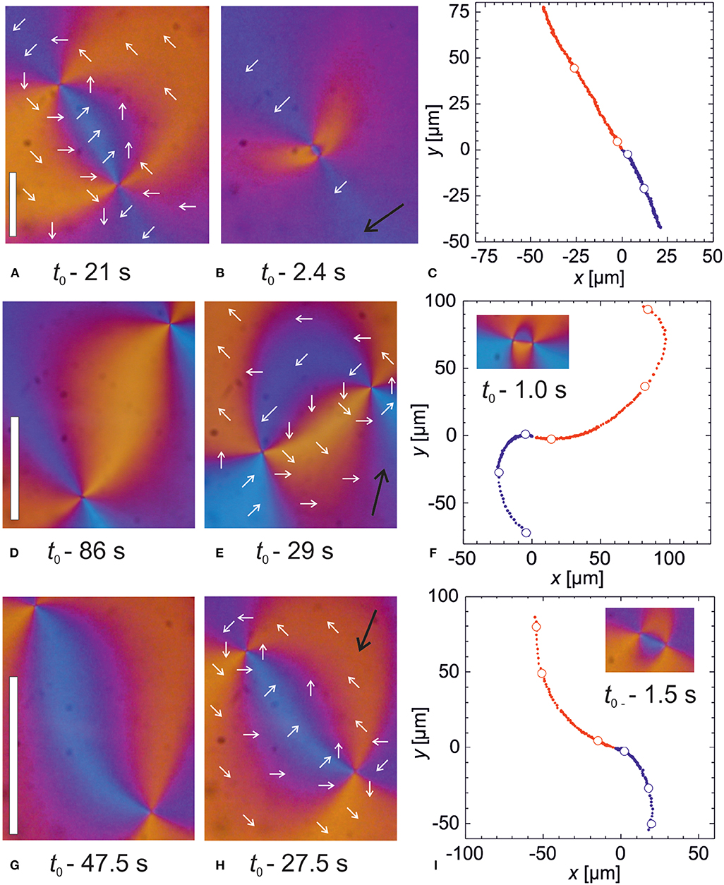
Figure 11. (A–C) Matching defect pair, δθ = 0, in perfect alignment, δϕ = 0. Times refer to the annihilation event, white circles in (C) mark the positions where (A,B) were recorded. (D–F) Same for mismatching, misaligned pair with initial angles δθ = +65°, δϕ = −36°, (G–I) mismatching, misaligned pair with initial angles δθ = −50°, δϕ = +79°. The white bar in (A) marks 50 μm, in (D,G) 100 μm. Black arrows indicate the orientation of the far director. Images reprinted from Missaoui et al. [43].
The static equilibrium solutions are certainly not exact when flow is present [55]. We note that in realistic coarsening scenarios, the director field surrounding adjacent pairs is influenced by all neighbors. Then, misalignment effects may be averaged out to a certain extent, while the mismatch between the partners remains an important parameter.
A previous investigation [32] of repulsive interactions of defects of identical topological charges S = +1 has shown some limitations of the classical defect interaction models in liquid crystals [61, 95, 97] but a good agreement of the predicted square-root law of the time dependence of the characteristic quantities. Defects were collected initially in a small spot of a smectic C film: the film contained a circular area of reduced film thickness, a so-called “hole” comprising defects with total topological charge N. In this hole, N defects of charge +1 each were located along the boundary. The situation is shown in Figure 5C. In different experiments, N was varied between 4 and 12. The defects repel each other but cannot enter the surrounding thicker film regions because their elastic energy increases linearly with film thickness. On the other hand, they prevent the hole from shrinking and extinction because they counteract a reduction of the hole radius. By manually destroying the hole [32], the defects are freed and they explode in a regular pattern (Figure 1A) on straight radial trajectories. It was found that the velocities are well-described by a square-root law R ∝ t1/2 with R being the distance from the central spot that contained the defects and t the time after extinction of the hole. It was further observed that because of the pinning of the c-director at +1 defect cores, interactions to farther away defects are partially screened by nearer ones. Finally, it was demonstrated that multiple +1 defects with tangential anchoring cannot be described as a superposition of solutions of single defects. They necessarily include additional distortions of the surrounding director field that are not considered in the classical interaction models. The latter two features are not relevant in systems with elastic isotropy, where +1 defects can adjust θ1 without barriers. They are, however, characteristic for any systems that require strictly tangential or radial vector fields around their +1 defects.
In an attempt to mimic cosmic string dynamics and the coarsening of complex string defect patterns, Chuang et al. [20, 21] studied nematics between sapphire plates. Rapid phase transitions from the isotropic phase were triggered either by a temperature quench or high pressure. The boundary conditions at the surfaces were not specified. They were presumably planar degenerate. In the nematic phase, a rich pattern of string defects occurred after the disorder-order transition. These defects were three-dimensional and of complex geometry. Nevertheless, the authors analyzed the 2D images and considered the mean density ρ of defects per area. They confirmed a coarsening ρ(t) ∝ t−1, as predicted by scaling arguments within an approximate model. In the late stages of coarsening, there were clear deviations from the t−1 scaling law, and ρ(t) dropped even faster than the t−2 scaling predicted for 3D systems. Comparable experiments by Pargellis et al. [56] were performed under well-defined boundary conditions. Defects of strength ±1 emerged at an isotropic-nematic interface in the cell midplane. The authors were able to obtain accurate quantitative data of the 2D defect density ρ(t). Approximately 1 min after the quench, this density followed the predicted t−1 decay. In an improved experimental geometry, Nagaya et al. [58] and Dierking et al. [44, 59] studied coarsening of defect patterns under isothermal conditions. Umbilics were formed in a material with Δε < 0 exposed to an electric field along the cell normal. In a 2D view, the authors consider the umbilics as defect patterns. These structures can be regarded as integer-strength defects (see Figure 1). The ρ ∝ 1/t coarsening law was confirmed. Similar coarsening experiments in SmC FSFs were reported by Pargellis et al. [78]. The films were comparably thick (of the order of 103 layers). Defects were created by temperature quenches. The texture between defect pairs showed an unusual appearance: instead of structures comparable to those found by other authors, the director distortions were localized in narrow inversion walls. This changes the defect dynamics qualitatively. The likely explanation of this discrepancy was given in section 4.2.1. One consequence was that the coarsening statistics changed qualitatively, the decay of ρ(t) became exponential. Since a reproducible thickness profile is difficult to control in very thick films, it is preferable to study defect pattern coarsening in submicrometer thin, uniform films.
Muzny [80] studied defect pattern coarsening in homogeneously thick FSFs with a purely mechanical preparation technique that does not involve temperature changes. The decay of the defect density ρ(t) ∝ t−1 in random many-defect patterns was confirmed in these experiments. The fact that the coarsening dynamics is rather similar in all these experiments, irrespective of the sample geometries, defect preparation methods and types of defects seem to indicate that the ρ ∝ t−1 scaling is a robust result that is independent of details of the elementary annihilation steps.
Models and experiments of 2D nematic and SmC defect interactions and dynamics were compiled in this review. The nematodynamic equations require that the defect separation R of an isolated conjugated pair scales as with the time to annihilation, irrespective of the presence of flow. This holds true as long as no other length scales enter the description, such as lateral confinement, the vicinity of defect cores, the Saffman length of advected air layers, or widths of inversion walls generated by external electric fields. The square-root scaling was confirmed in many experiments with smectic films and nematics in sandwich cells. Material flow accelerates the motion of the positively charged defect and decelerates the negative counterpart; the annihilation point is thus shifted toward the negatively charged defect. The dominating term is related to the ratio γ1/α4. Elastic anisotropy has a similar effect, which is usually much weaker than flow coupling. Both predictions qualitatively agree with experiments. Nematics confined to sandwich cells often suffer from a more or less 3D character of the director field. Real quasi-2D systems can be realized using free-standing smectic C films or Langmuir films. The former display full flow coupling, as the surrounding fluid is often negligible, whereas the latter eliminate flow in the film plane through coupling to the bulk water phase.
Most of the existing models of defect dynamics disregard the mutual orientation of the defects and the pair's orientation in the far director field. They also do not account for the special fixed configurations of +1 defects (preferentially tangential or radial), which influence the relaxation dynamics qualitatively. Recent studies have brought this problem into focus [43, 99, 100]. The theory predicts curved defect trajectories and rotations of the defects on the way to annihilation. Quantitatively, there are some discrepancies between model and experiments, suggesting that a single-elastic constant approach without flow oversimplifies the physical situation. Pinning of the phase of +1 defects in general requires additional director distortions in configurations of multiple defects, altering the repulsion dynamics [32]. The influence of lateral confinement as well as a possible coupling to thermal fluctuations or a surrounding low-viscosity fluid still need to be incorporated in the models of thin films.
Defect diffusion has been studied in FSF [79–81]. In thick films, normal diffusion with coefficients of the order of a few μm2/s was observed, while in very thin films of only few molecular layers, coupling of flow to the ambient air seems to attenuate the diffusive motion.
This review has focused on systems where defect dynamics is driven by interactions with the surrounding director field and flow driven by the director dynamics. An interesting extension with promising perspectives is the study of systems where defects are generated, moved, and recombined by flow fields of external origin, such as active nematics [41, 136], and microfluidic systems where external flow can tune the topology of the samples [137]. In addition, the vast field of disclinations interacting with solid or liquid inclusions in liquid crystals has been completely left open here. Comprehensive reviews of static arrangements of solid or liquid inclusions in combination with defects can be found in Dolganov et al. [33] and Stannarius and Harth [92]. The dynamics of such symbiotic structures deserve considerable interest in future studies. Another promising perspective to consider when preparing self-assembled structures is the well-controlled creation of defect patterns with proper surface structuring of nematic cells [138]. Such structures can be switched electrically, and diffraction properties of nematic cells can be influenced by means of electric fields.
Both authors contributed equally to this publication.
The German Science Foundation DFG is acknowledged for support within projects STA 425/42-1, HA 8467/2-1, and HA 8467/3. The German Space Administration DLR is acknowledged for support within grant 50WM1744.
The authors declare that the research was conducted in the absence of any commercial or financial relationships that could be construed as a potential conflict of interest.
The authors acknowledge A. Missaoui, J. Selinger, X. Tang, and E. Virga for fruitful discussions and P. Salamon for participating in some experiments.
1. ^For simplicity, we will use the term director in smectic films synonymously to denote the c-director.
1. Poulin P, Stark H, Lubensky TC, Weitz DA. Novel colloidal interactions in anisotropic fluids. Science. (1997) 275:1770–3. doi: 10.1126/science.275.5307.1770
2. Poulin P, Weitz DA. Inverted and multiple emulsions. Phys Rev E. (1998) 57:626–37. doi: 10.1103/PhysRevE.57.626
3. Muševič I, Škarabot M, Tkalec U, Ravnik M, Žumer S. Two-dimensional nematic colloidal crystals self-assembled by topological defects. Science. (2006) 313:954–8. doi: 10.1126/science.1129660
4. Tkalec U, Ravnik M, Čopar S, Žumer S, Muševič I. Reconfigurable knots and links in chiral nematic colloids. Science. (2011) 333:62–5. doi: 10.1126/science.1205705
5. Muševič I. Interactions, topology and photonic properties of liquid crystal colloids and dispersions. Eur Phys J ST. (2019) 227:2455–85. doi: 10.1140/epjst/e2019-800107-y
6. Brugues J, Ignes-Mullol J, Casademunt J, Sagues F. Probing elastic anisotropy from defect dynamics in Langmuir monolayers. Phys Rev Lett. (2008) 100:037801. doi: 10.1103/PhysRevLett.100.037801
7. Weiler CN, Neely TW, Scherer DR, Bradley AS, Davis MJ, Anderson BP. Spontaneous vortices in the formation of Bose-Einstein condensates. Nature. (2008) 455:948–51. doi: 10.1038/nature07334
8. Polkovnikov A, Sengupta K, Silva A, Vengalattore M. Nonequilibrium dynamics of closed interacting quantum systems. Rev Mod Phys. (2011) 83:863. doi: 10.1103/RevModPhys.83.863
9. Kudo K, Kawaguchi Y. Coarsening dynamics driven by vortex-antivortex annihilation in ferromagnetic Bose-Einstein condensates. Phys Rev A. (2015) 91:053609. doi: 10.1103/PhysRevA.91.053609
10. Seo SW, Kwon WJ, Kang S, Shin Y. Collisional dynamics of half-quantum vortices in a spinor Bose-Einstein condensate. Phys Rev Lett. (2016) 116:185301. doi: 10.1103/PhysRevLett.116.185301
11. Abrikosov AA. On the magnetic properties of superconductors of the second group. JETP. (1957) 32:1442.
12. Ruutu VMH, Eltsov VB, Gill AJ, Kibble TWB, Krusius M, Makhlin YG, et al. Vortex formation in neutron-irradiated superfluid 3He as an analogue to cosmological defect formation. Nature. (1996) 382:334. doi: 10.1038/382334a0
13. Bäuerle C, Bunkov YM, Fisher SN, Godfrin H, Picket GR. Laboratory simulation of cosmic string formation in the early universe using superfluid 3He. Nature. (1996) 382:332. doi: 10.1038/382332a0
14. Bäuerle C, Bunkov YM, Fisher SN, Godfrin H, Pickett GR. Do not try this at home. Nature. (1996) 383:570. doi: 10.1038/383570b0
15. Wachowiak A, Wiebe J, Bode M, Pietzsch O, Morgenstern M, Wiesendanger R. Direct observation of internal spin structure of magnetic vortex cores. Science. (2002) 298:577–80. doi: 10.1126/science.1075302
16. Hertel R, Schneider CM. Exchange explosions: magnetization dynamics during vortex-antivortex annihilation. Phys Rev Lett. (2006) 97:177202. doi: 10.1103/PhysRevLett.97.177202
17. Rissanen I, Laurson L. Coarsening dynamics of topological defects in thin permalloy films. Phys Rev E. (2016) 94:144428. doi: 10.1103/PhysRevB.94.144428
18. Volovik GE, Mineev VP. Particle-like solitons in superfluid 3He phases. Sov Phys. (1977) 73:767–73.
19. Ray R, Srivastava AM. Measuring cosmic defect correlations in liquid crystals. Phys Rev D. (2004) 69:103525. doi: 10.1103/PhysRevD.69.103525
20. Chuang I, Durrer R, Yurke B, Turok N. Cosmology in the laboratory: defect dynamics in liquid crystals. Science. (1991) 251:1336–42. doi: 10.1126/science.251.4999.1336
21. Chuang I, Yurke B, Turok N. Late-time coarsening dynamics in a nematic liquid crystal. Phys Rev Lett. (1991) 66:2472. doi: 10.1103/PhysRevLett.66.2472
22. Zurek WH. Cosmological experiments in condensed matter systems. Phys Rep. (1996) 276:177–221. doi: 10.1016/S0370-1573(96)00009-9
23. Bowick MJ, Chandar L, Schiff EA, Srivastava AM. The cosmological Kibble mechanism in the laboratory: string formation in liquid crystals. Science. (1994) 263:943–5. doi: 10.1126/science.263.5149.943
24. Trebin HR. Defects in liquid crystals and cosmology. Liq Cryst. (1998) 24:127–30. doi: 10.1080/026782998207659
25. Kibble T, Srivastava A. Condensed matter analogues of cosmology. J Phys Condens Matter. (2013) 25:400301. doi: 10.1088/0953-8984/25/40/400301
26. Brinkman WF, Cladis PE. Defects in liquid crystals. Phys Today. (1982) 35:48. doi: 10.1063/1.2915094
27. Liu C, Muthukumar M. Annihilation kinetics of liquid crystal defects. J Chem Phys. (1997) 106:7822. doi: 10.1063/1.473740
28. Wang W, Shiwaku T, Hashimoto T. Experimental study of dynamics of topological defects in nematic polymer liquid crystals. J Chem Phys. (1997) 108:1618. doi: 10.1063/1.475532
29. Silvestre NM, Patricio P, Telo da Gama MM, Pattanaporkratana A, Park CS, Maclennan JE, et al. Modeling dipolar and quadrupolar defect structures generated by chiral islands in freely suspended liquid crystal films. Phys Rev E. (2009) 80:041708. doi: 10.1103/PhysRevE.80.041708
30. Fukuda JI, Žumer S. Quasi-two-dimensional Skyrmion lattices in a chiral nematic liquid crystal. Nat Commun. (2011) 2:246. doi: 10.1038/ncomms1250
31. Pieranski P, Godinho MH, Čopar S. Persistent quasiplanar nematic texture: its properties and topological defects. Phys Rev E. (2016) 94:042706. doi: 10.1103/PhysRevE.94.042706
32. Stannarius R, Harth K. Defect interactions in anisotropic two-dimensional fluids. Phys Rev Lett. (2016) 117:157801. doi: 10.1103/PhysRevLett.117.157801
33. Dolganov PV, Cluzeau P, Dolganov VK. Interaction and self-organization of inclusions in two-dimensional free-standing smectic films. Liquid Cryst Rev. (2019) 7:1–29. doi: 10.1080/21680396.2019.1586590
34. Tkalec U, Muševič I. Topology of nematic liquid crystal colloids confined to two dimensions. Soft Matter. (2013) 9:8140–50. doi: 10.1039/c3sm50713k
35. Čopar S, Clark NA, Ravnik M, Žumer S. Elementary building blocks of nematic disclination networks in densely packed 3D colloidal lattices. Soft Matter. (2013) 9:8203–9. doi: 10.1039/c3sm50475a
36. Serra F, Vishnubhatla KC, Buscaglia M, Roberto Osellame RC, Cerulloc G, Bellini T. Topological defects of nematic liquid crystals confined in porous networks. Soft Matter. (2011) 7:10945. doi: 10.1039/c1sm05813d
37. Araki T, Buscaglia M, Bellini T, Tanaka H. Memory and topological frustration in nematic liquid crystals confined in porous materials. Nat Mater. (2011) 10:303–9. doi: 10.1038/nmat2982
38. Araki T, Serra F, Tanaka H. Defect science and engineering of liquid crystals under geometrical frustration. Soft Matter. (2013) 9:8107–20. doi: 10.1039/c3sm50468a
39. Yao X, Zhang H, Chen JZY. Topological defects in two-dimensional liquid crystals confined by a box. Phys Rev E. (2018) 97:052707. doi: 10.1103/PhysRevE.97.052707
40. Urbanski M, Reyes CG, Noh J, Sharma A, Geng Y, Jampani VSR, et al. Liquid crystals in micron-scale droplets, shells and fibers. J Phys: Cond Mat. (2017) 29:133003. doi: 10.1088/1361-648X/aa5706
41. Doostmohammadi A, Ignés-Mullol J, Yeomans JM, Sagués F. Active nematics. Nat Commun. (2018) 9:3246. doi: 10.1038/s41467-018-05666-8
42. Kempf F, Mueller R, Frey E, Yeomans JM, Doostmohammadi A. Active matter invasion. Soft Matter. (2019) 15:7538–46. doi: 10.1039/C9SM01210A
43. Missaoui A, Harth K, Salamon P, Stannarius R. Annihilation of point defect pairs in freely suspended liquid-crystal films. Phys Rev Res. (2020) 2:013080. doi: 10.1103/PhysRevResearch.2.013080
44. Dierking I, Marshall O, Wright J, Bulleid N. Annihilation dynamics of umbilical defects in nematic liquid crystals under applied electric fields. Phys Rev E. (2005) 71:061709. doi: 10.1103/PhysRevE.71.061709
45. Friedel G. Les états mésomorphes de la matiére. Ann Phys. (1922) 9:273–474. doi: 10.1051/anphys/192209180273
46. Young CY, Pindak R, Clark NA, Meyer RB. Light-scattering study of two-dimensional molecular-orientation fluctuations in a freely suspended ferroelectric liquid-crystal film. Phys Rev Lett. (1978) 40:773. doi: 10.1103/PhysRevLett.40.773
47. Oswald P, Pieranski P. Nematic and Cholesteric Liquid Crystals: Concepts and Physical Properties Illustrated by Experiments. Boca Raton, FL: Taylor & Francis (2005). doi: 10.1201/9780203023013
48. Oswald P, Pieranski P. Smectic and Columnar Liquid Crystals: Concepts and Physical Properties Illustrated by Experiments. Boca Raton, FL: Taylor & Francis (2006). doi: 10.1201/9781420036343
49. Schopohl N, Sluckin T. Defect core structure in nematic liquid-crystals. Phys Rev Lett. (1987) 59:2582–4. doi: 10.1103/PhysRevLett.59.2582
50. Qian H, Sheng P. Generalized hydrodynamic equations for nematic liquid crystals. Phys Rev E. (1998) 58:7475. doi: 10.1103/PhysRevE.58.7475
51. Toth G, Denniston C, Yeomans JM. Hydrodynamics of topological defects in nematic liquid crystals. Phys Rev Lett. (2002) 88:105504. doi: 10.1103/PhysRevLett.88.105504
52. Denniston C, Orlandini E, Yeomans JM. Simulations of liquid crystal hydrodynamics in the isotropic and nematic phases. Europhys Lett. (2000) 52:481. doi: 10.1209/epl/i2000-00463-3
53. Svenšek D, Žumer S. Hydrodynamics of pair-annihilating disclination lines in nematic liquid crystals. Phys Rev E. (2002) 66:021712. doi: 10.1103/PhysRevE.66.021712
54. Harth K, Eremin A, Stannarius R. Vortex flow in free-standing smectic C films driven by elastic distortions. Soft Matter. (2011) 7:2858. doi: 10.1039/c0sm01040e
55. Svenšek D, Žumer S. Hydrodynamics of pair-annihilating disclinations in SmC films. Phys Rev Lett. (2003) 90:155501. doi: 10.1103/PhysRevLett.90.219901
56. Pargellis AN, Green S, Yurke B. Planar XY-model dynamics in a nematic liquid crystal system. Phys Rev E. (1994) 49:4250. doi: 10.1103/PhysRevE.49.4250
57. Nagaya T, Hotta H, Orihara H, Ishibashi Y. Observation of annihilation process of disclinations emerging from bubble domains. J Phys Soc Jpn. (1991) 60:1572. doi: 10.1143/JPSJ.60.1572
58. Nagaya T, Hotta H, Orihara H, Ishibashi Y. Experimental study of the coarsening dynamics of +1 and −1 disclinations. J Phys Soc Jpn. (1992) 61:3511. doi: 10.1143/JPSJ.61.3511
59. Dierking I, Ravnik M, Lark E, Healey J, Alexander GP, Yeomans JM. Anisotropy in the annihilation dynamics of umbilic defects in nematic liquid crystals. Phys Rev E. (2012) 85:021703. doi: 10.1103/PhysRevE.85.021703
60. Chuang I, Yurke B, Pargellis AN, Turok N. Coarsening dynamics in uniaxial nematic liquid crystals. Phys Rev E. (1993) 47:3343. doi: 10.1103/PhysRevE.47.3343
61. Minoura K, Kimura Y, Ito K, Hayakawa R. Dynamics of annihilation process of disclination pairs in nematic liquid crystals. Mol Cryst Liq Cryst. (1997) 302:345–55. doi: 10.1080/10587259708041847
62. Bogi A, Martinot-Lagarde P, Dozov I, Nobili M. Anchoring screening of defects interaction in a nematic liquid crystal. Phys Rev Lett. (2002) 89:225501. doi: 10.1103/PhysRevLett.89.225501
63. Blanc C, Svenšek D, Žumer S, Nobili M. Dynamics of nematic liquid crystal disclinations: the role of the backflow. Phys Rev Lett. (2005) 95:097802. doi: 10.1103/PhysRevLett.95.097802
64. Alexander GP, Chen BG, Matsumoto EA, Kamien RD. Colloquium: disclination loops, point defects, and all that in nematic liquid crystals. Rev Mod Phys. (2011) 84:1229. doi: 10.1103/RevModPhys.84.497
65. Yanagimachi T, Yamamura SYY, Saito K. Cell gap dependence of nematic backflow around annihilating disclination pair. J Phys Soc Jpn. (2012) 81:074603. doi: 10.1143/JPSJ.81.074603
66. Yanagimachi T, Yamamura SYY, Saito K. Backflow-induced asymmetric annihilation of nematic disclinations under strong anchoring condition. J Phys Soc Jpn. (2012) 81:034601. doi: 10.1143/JPSJ.81.034601
67. Shen Y, Dierking I. Annihilation dynamics of topological defects induced by microparticles in nematic liquid crystals. Soft Matter. (2019) 15:8749. doi: 10.1039/C9SM01710K
68. Oswald P, Ignés-Mullol J. Backflow-induced asymmetric collapse of disclination lines in liquid crystals. Phys Rev Lett. (2005) 95:027801. doi: 10.1103/PhysRevLett.95.027801
69. Shahzamanian MA, Kadivar E. Disclinations dynamics in confined nematic liquid crystals: strong anchoring. Liq Cryst. (2006) 33:941–5. doi: 10.1080/02678290600900660
70. Fernandez-Nieves A, Vitelli V, Utada AS, Link DR, Marquez M, Nelson DR, et al. Novel defect structures in nematic liquid crystal shells. Phys Rev Lett. (2007) 99:157801. doi: 10.1103/PhysRevLett.99.157801
71. Liang HL, Schymura S, Rudquist P, Lagerwall J. Nematic-smectic transition under confinement in liquid crystalline colloidal shells. Phys Rev Lett. (2011) 106:247801. doi: 10.1103/PhysRevLett.106.247801
72. Lopez-Leon T, Fernandez-Nieves A, Nobili M, Blanc C. Nematic-smectic transition in spherical shells. Phys Rev Lett. (2011) 106:247802. doi: 10.1103/PhysRevLett.106.247802
73. Lopez-Leon T, Bates MA, Fernandez-Nieves A. Defect coalescence in spherical nematic shells. Phys Rev E. (2012) 86:030702. doi: 10.1103/PhysRevE.86.030702
74. Liang HL, Zentel R, Rudquist P, Lagerwall J. Towards tunable defect arrangements in smectic liquid crystal shells utilizing the nematic-smectic transition in hybrid-aligned geometries. Soft Matter. (2012) 8:5443. doi: 10.1039/c2sm07415j
75. Liang HL, Noh JH, Zentel R, Rudquist P, Lagerwall J. Tuning the defect configurations in nematic and smectic liquid crystalline shells. Philos Trans R Soc A. (2013) 371:20120258. doi: 10.1098/rsta.2012.0258
76. Noh JH, Henx B, Lagerwall JPF. Taming liquid crystal self-assembly: the multifaceted response of nematic and smectic shells to polymerization. Adv Mat. (2016) 28:10170. doi: 10.1002/adma.201603158
77. Gim MJ, Beller DA, Yoon DK. Morphogenesis of liquid crystal topological defects during the nematic-smectic A phase transition. Nat Commun. (2017) 8:15453. doi: 10.1038/ncomms15453
78. Pargellis AN, Finn P, Goodby JW, Panizza P, Yurke B, Cladis PE. Defect dynamics and coarsening dynamics in smectic-C films. Phys Rev A. (1992) 46:7765. doi: 10.1103/PhysRevA.46.7765
79. Muzny CD, Clark NA. Direct observation of the Brownian motion of a liquid-crystal topological defect. Phys Rev Lett. (1992) 68:804–7. doi: 10.1103/PhysRevLett.68.804
80. Muzny C. Properties of defects in freely suspended smectic C thin films (Ph.D. Thesis). University of Colorado, Boulder, CO, United States (1994).
81. Wachs K. Dynamics of smectic-c point disclinations infreely-suspended liquid crystal films (B. A. Thesis). University of Colorado, Boulder, CO, United States (2014).
82. Nguyen DH. Smectic Liquid Crystal Freely Suspended Films: Testing Beds for the Physics in Thin Membranes. (Ph.D. Thesis) Boulder, CO: University of Colorado (2011).
83. Radzihovsky SP, Cranfill C, Nguyen Z, Park CS, Maclennan JE, Glaser MA, et al. Two-dimensional island emulsions in ultrathin, freely-suspended smectic liquid crystal films. Soft Matter. (2017) 13:6314. doi: 10.1039/C7SM01584D
84. Clark NA, Eremin A, Glaser MA, Hall NR, Harth K, Klopp C, et al. Realization of hydrodynamic experiments on quasi-2D liquid crystal films in microgravity. Adv Space Res. (2017) 60:737. doi: 10.1016/j.asr.2017.04.014
85. Harth K, Stannarius R. Deep holes in free-standing smectic C films. Ferroelectrics. (2014) 468:92. doi: 10.1080/00150193.2014.933655
86. Dolganov PV, Shuravin NS, Fukuda A. Two-dimensional hexagonal smectic structure formed by topological defects. Phys Rev E. (2016) 93:032704. doi: 10.1103/PhysRevE.93.032704
87. May K, Harth K, Trittel T, Stannarius R. Dynamics of freely floating smectic bubbles. Europhys Lett. (2012) 100:16003. doi: 10.1209/0295-5075/100/16003
88. Maclennan JE. Spontaneous director rotation in freely suspended ferroelectric liquid-crystal films. Europhys Lett. (1990) 13:435. doi: 10.1209/0295-5075/13/5/010
89. Harth K, Stannarius R. Corona patterns around inclusions in freely suspended smectic films. Eur Phys J E. (2009) 28:265. doi: 10.1140/epje/i2008-10404-6
90. Harth K, Eremin A, Stannarius R. A gallery of meniscus patterns of free-standing smectic films. Ferroelectrics. (2012) 431:59. doi: 10.1080/00150193.2012.684630
91. Harth K. Episodes of the Life and Death of Thin Fluid Membranes. (Ph.D. Thesis) Magdeburg: Otto von Guericke Universität Magdeburg (2016). doi: 10.25673/4391
92. Stannarius R, Harth K. Inclusions in freely suspended smectic films. In: Lagerwall S, Scalia G, editors. Liquid Crystals With Nano and Microparticles. Vol. 1. London: World Scientific (2016). p. 361. doi: 10.1142/9789814619264_0011
93. Eremin A, Nemeş A, Stannarius R, Pelzl G, Weissflog W. Spontaneous bend patterns in homochiral ferroelectric SmCP films: evidence for a negative effective bend constant. Soft Matter. (2008) 4:2186. doi: 10.1039/b804845b
94. Dolganov PV, Kats EI, Dolganov VK, Cluzeau P. Linear defects forming the ground state of polar free standing smectic-C* films. Soft Matter. (2019) 14:7174. doi: 10.1039/C8SM01276H
95. Dafermos CM. Disinclinations in liquid crystals. Quart J Mech Appl Math. (1970) 23:S49. doi: 10.1093/qjmam/23.2.49
96. Chandrasekhar S, Ranganath GS. The structure and energetics of defects in liquid crystals. Adv Phys. (1986) 35:507–96. doi: 10.1080/00018738600101941
97. Kleman M, Lavrentovich OD. Soft Matter Physics: An Introduction. Berlin: Springer Verlag (2003). doi: 10.1007/b97416
98. Gartland EC Jr, Sonnet AM, Virga EG. Elastic forces on nematic point defects. Continuum Mech Thermodyn. (2002) 14:307–19. doi: 10.1007/s00161-002-0099-8
99. Vromans AJ, Giomi L. Orientational properties of nematic disclinations. Soft Matter. (2016) 12:6490–5. doi: 10.1039/C6SM01146B
100. Tang X, Selinger JV. Orientation of topological defects in 2D nematic liquid crystals. Soft Matter. (2017) 13:5481. doi: 10.1039/C7SM01195D
101. Chandrasekhar S. Liquid Crystals. Cambridge: Cambridge University Press (1992). doi: 10.1017/CBO9780511622496
103. Tang X, Selinger JV. Theory of defect motion in 2D passive and active nematic liquid crystals. Soft Matter. (2019) 15:587. doi: 10.1039/C8SM01901K
104. Imura H, Okano K. Friction coefficient for a moving disinclination in a nematic liquid crystal. Phys Lett. (1973) 42A:403. doi: 10.1016/0375-9601(73)90728-7
105. Pleiner H. Dynamics of a disclination point in smectic-C and -C* liquid-crystal films. Phys Rev A. (1988) 37:3986. doi: 10.1103/PhysRevA.37.3986
106. Ryskin G, Kremenetsky M. Drag force on a line defect moving through an otherwise undisturbed field: disclination line in a nematic liquid crystal. Phys Rev Lett. (1991) 67:1574. doi: 10.1103/PhysRevLett.67.1574
107. Radzihovsky L. Anomalous energetics and dynamics of moving vortices. Phys Rev Lett. (2015) 115:247801. doi: 10.1103/PhysRevLett.115.247801
108. Stewart IW. The Static and Dynamic Continuum Theory of Liquid Crystals. London; New York, NY: Taylor & Francis (2004).
109. Kats EI, Lebedev VV, Malinin SV. Disclination motion in liquid crystalline films. J Exp Theor Phys. (2002) 95:714–27. doi: 10.1134/1.1520604
110. Biscari P, Sluckin TJ. A perturbative approach to the backflow dynamics of nematic defects. Eur J Appl Math. (2012) 23:181–200. doi: 10.1017/S0956792510000343
111. Sonnet AM, Virga EG. Flow and reorientation in the dynamics of nematic defects. Liq Cryst. (2009) 36:1185. doi: 10.1080/02678290903034480
112. Denniston C, Tóth G, Yeomans JM. Domain motion in confined liquid crystals. J Stat Phys. (2002) 107:187. doi: 10.1023/A:1014562721540
113. Mandal S, Mazza MG. Multiparticle collision dynamics for tensorial nematodynamics. Phys Rev E. (2019) 99:063319. doi: 10.1103/PhysRevE.99.063319
114. Denniston C, Orlandini E, Yeomans JM. Phase ordering in nematic liquid crystals. Phys Rev E. (2001) 64:021701. doi: 10.1103/PhysRevE.64.021701
115. Vertogen G. The equations of motion for nematics. Z Naturforsch A. (1983) 38:1273–5. doi: 10.1515/zna-1983-1201
116. Sonnet AM, Virga EG. Dynamics of dissipative ordered fluids. Phys Rev E. (2001) 64:031705. doi: 10.1103/PhysRevE.64.031705
117. Biscari P, Sluckin TJ. Field-induced motion of nematic disclinations. SIAM J Appl Math. (2005) 65:2141. doi: 10.1137/040618898
118. Guimarães RR, Mendes RS, Fernandes PRG, Mukai H. Dynamics of topological monopoles annihilation on a fibre in a thick and thin nematic layer. J Phys Condens Matter. (2013) 25:404203. doi: 10.1088/0953-8984/25/40/404203
119. Ribeiro HV, Guimarães RR, Teixeira-Souza RT, Mukai H, Fernandes PRG, Lenzi EK, et al. Antipersistent behavior of defects in a lyotropic liquid crystal during annihilation. Phys Rev E. (2013) 87:054501. doi: 10.1103/PhysRevE.87.054501
120. Dolganov PV, Shuravin NS, Dolganov VK, Kats EI, Fukuda A. Topological defects in smectic islands formed in antiferroelectric freestanding nanofilms. Surf Innov. (2019) 7:168. doi: 10.1680/jsuin.18.00059
121. Bohley C, Stannarius R. Inclusions in free standing smectic liquid crystal films. Soft Matter. (2008) 4:683. doi: 10.1039/b715124a
122. Vallvé MA, Ignés-Mullol J. Dynamics of point defects and stripe textures in smectic-C Langmuir monolayers. Eur Phys J E. (2009) 30:403–9. doi: 10.1140/epje/i2009-10539-x
123. Wang W, Hashimoto T, Lieser G, Wegner G. Elastic constant anisotropy, core structure of wedge disclinations and optical texture of main-chain P-4-BCMU liquid crystals. J Polym Sci Pt B-Polymer Phys. (1994) 32:2171–86. doi: 10.1002/polb.1994.090321305
124. Gu Q, Wu C, Chen S, Huang Y. Decoration of disclinations by solidification-induced band texture and focal-conic texture for a low-molar-mass liquid crystal. Chin Sci Bull. (2002) 47:1711–3. doi: 10.1007/BF03183313
125. Drummy L, Voigt-Martin I, Martin D. Analysis of displacement fields near dislocation cores in ordered polymers. Macromolecules. (2001) 34:7416–26. doi: 10.1021/ma010003b
126. Zhang S, Terentjev E, Donald A. Nature of disclination cores in liquid crystals. Liquid Cryst. (2005) 32:69–75. doi: 10.1080/02678290512331324057
127. Zhou S, Shiyanovskii SV, Park HS, Lavrentovich OD. Fine structure of the topological defect cores studied for disclinations in lyotropic chromonic liquid crystals. Nat Commun. (2017) 8:14974. doi: 10.1038/ncomms14974
128. Cladis P, Kleman M, Pieranski P. New method for decoration of mesomorphic phase of para methoxybenzylidene para betylaniline. Compt Rend Hebd Acad Sci Ser B. (1971) 273:275.
129. Lee JB, Pelcovits RA, Meyer RB. Role of electrostatics in the texture of islands in free standing ferroelectric liquid-crystal films. Phys Rev E. (2007) 75:011701. doi: 10.1103/PhysRevE.75.051701
130. Cladis PE, Finn PL, Brand HR. Stable coexistence of spiral and target patterns in freely suspended films of smectic-C liquid crystals. Phys Rev Lett. (1995) 75:1518. doi: 10.1103/PhysRevLett.75.1518
131. Eremin A, Bohley C, Stannarius R. Stick-slip dynamics around a topological defect in free standing smectic films. Phys Rev E. (2006) 74:040701(R). doi: 10.1103/PhysRevE.74.040701
132. Nguyen ZH, Atkinson M, Park CS, Maclennan J, Glaser M, Clark N. Crossover between 2D and 3D fluid dynamics in the diffusion of islands in ultrathin freely suspended smectic films. Phys Rev Lett. (2016) 105:268304. doi: 10.1103/PhysRevLett.105.268304
133. Eremin A, Baumgarten S, Harth K, Stannarius R, Nguyen ZH, Goldfain A, et al. Two-dimensional microrheology of freely suspended liquid crystal films. Phys Rev Lett. (2011) 107:268301. doi: 10.1103/PhysRevLett.107.268301
134. Hughes BD, Pailthorpe BA, White LR. The translational and rotational drag on a cylinder moving in a membrane. J Fluid Mech. (1981) 110:349. doi: 10.1017/S0022112081000785
135. Völtz C, Stannarius R. Self-organization of isotropic droplets in smectic-C free-standing films. Phys Rev E. (2004) 70:061702. doi: 10.1103/PhysRevE.70.061702
136. Hardouin J, Hughes R, Doostmohammadi A, Laurent J, Lopez-Leon T, Yeomans JM, et al. Reconfigurable flows and defect landscape of confined active nematics. Commun Phys. (2019) 2:121. doi: 10.1038/s42005-019-0221-x
137. Giomi L, Kos Ž, Ravnik M, Sengupta A. Cross-talk between topological defects in different fields revealed by nematic microfluidics. Proc Natl Acad Sci USA. (2017) 114:E5771. doi: 10.1073/pnas.1702777114
Keywords: defects, disclinations, liquid crystals, two-dimensional systems, continuum theory, freely suspended films, fluid mechanics, phase transitions
Citation: Harth K and Stannarius R (2020) Topological Point Defects of Liquid Crystals in Quasi-Two-Dimensional Geometries. Front. Phys. 8:112. doi: 10.3389/fphy.2020.00112
Received: 28 November 2019; Accepted: 23 March 2020;
Published: 25 May 2020.
Edited by:
Francesca Serra, Johns Hopkins University, United StatesReviewed by:
Julio Cesar Armas-Perez, University of Guanajuato, MexicoCopyright © 2020 Harth and Stannarius. This is an open-access article distributed under the terms of the Creative Commons Attribution License (CC BY). The use, distribution or reproduction in other forums is permitted, provided the original author(s) and the copyright owner(s) are credited and that the original publication in this journal is cited, in accordance with accepted academic practice. No use, distribution or reproduction is permitted which does not comply with these terms.
*Correspondence: Kirsten Harth, a2lyc3Rlbi5oYXJ0aEBvdmd1LmRl
Disclaimer: All claims expressed in this article are solely those of the authors and do not necessarily represent those of their affiliated organizations, or those of the publisher, the editors and the reviewers. Any product that may be evaluated in this article or claim that may be made by its manufacturer is not guaranteed or endorsed by the publisher.
Research integrity at Frontiers
Learn more about the work of our research integrity team to safeguard the quality of each article we publish.