 Zhen Liao
 Guo Qing Luo*
 Bai Cao Pan
- Key Laboratory of RF Circuits and System of Ministry of Education, Hangzhou Dianzi University, Hangzhou, China
As an analog of the role of surface plasmons in optical antenna, spoof surface plasmons enable far-field radiation of antenna at microwave frequencies. Here, a plasmonic metamaterial supporting spoof surface plasmons is experimentally demonstrated for horizontally polarized omnidirectional radiation in the microwave region. A simple and intuitive working principle in the spoof surface plasmonic metamaterial design is provided, along with full-wave simulations that agree well with the experimental results. The low profile and compact design with the omnidirectional radiation pattern promises a wide range of applications, such as ceiling antennas, surface-mounted indoor antennas, and automobile antennas in microwave and radio frequencies.
Introduction
Localized Surface Plasmon (LSP) characteristics of the metallic nano-rod have gained tremendous interest over the past few years, especially with respect to the promising candidate for optical antennas [1]. Optical antennas are strongly analogous to their radio frequency (RF) and microwave counterparts, their purpose is to convert the energy of free propagating radiation to localized energy, and vice versa [2–6]. However, there are crucial differences between their physical properties and scaling behavior. Firstly, the size of RF antennas and wavelength are similar, and are usually several centimeters. Whereas, optical antennas are always in subwavelength scale and generate subwavelength “hotspots” around them. Secondly, metals are supposed to be a perfect electrical conductor (PEC) at microwave and RF frequencies, nevertheless, they are plasmons described as free electron gas at optical frequencies [7]. Therefore, these differences pose another challenge and limit the ability to extend current understanding from RF antennas to the optical spectrum, and vice versa.
It has recently been shown that spiral corrugated metamaterials can support spoof surface plasmons modes whose resonant wavelengths are much larger than the size of the structures, usually termed spoof localized surface plasmon (spoof LSP) resonances [8–10]. The spoof LSP modes in this geometry is quantitatively investigated by a metamaterial approximation, in which a textured perfect electric conductor (PEC) is treated as a homogeneous effective medium [8]. Furthermore, the deep subwavelength metallic spiral structures (MSS) support spoof magnetic LSP resonance as well as electrical surface plasmon modes [10, 11]. Thanks to the existence of spoof LSP mode, all the capabilities found for LSP in the optical regime can be directly transferred to lower frequencies. This enables a wide range of applications, including energy transport [12, 13], sensing [14, 15], topological protection [16], and field enhancement [17] in microwave and RF frequencies. Besides LSP, surface plasmon polaritons (SPPs) also have useful applications, such as SPP-enabled slow light devices [18] and SPP-induced transparency [19, 20]. At the same time, spoof surface plasmon polariton (SSPPs) at microwave frequencies exhibiting similar behaviors to real surface plasmon polariton (SPPs) have also been widely studied and applied to design transmission lines [21–24]. However, antennas based on spoof LSP resonances have not been achieved in a lower frequency range.
High performance antennas with omnidirectional radiation in the horizontal polarization are in great demand, fueled by the rapid growth of wireless communication systems. Horizontal polarization wireless signals equally cover all directions of the azimuthal plane, resulting in a 10-dB higher power gain than their vertically polarized counterparts [25, 26]. To date, various approaches have been developed to generate horizontally polarized omnidirectional beams, including the turnstile antennas consisting of cross dipoles in a horizontal plane [27, 28], a small loop antenna with uniform current distribution [7], the Alford loop antennas [29, 30], and dielectric resonator antenna (DRA) [31]. These methods, however, have several limitations. For instance, turnstile antennas have a narrow operating bandwidth. The small loop antenna has small radiation resistance and high reactance, which makes it difficult to be matched. The Alford loop antennas have an undesirable radiation performance in horizontal plane that occurs at high operating frequency. Meanwhile, the TE010 mode of a cylindrical dielectric resonator antenna (DRA) has azimuthal circulating electric fields, which are tangential to the circular plane. The DRA resonating at TE010 mode acts like a magnetic dipole in axial direction to radiate a horizontally polarized omnidirectional radiation pattern. Although the DRA has a subwavelength size, the antenna must have a certain thickness. The proposed DRA [31] achieves an omnidirectional radiation pattern for the horizontal component at 3 GHz, while its diameter is 25 mm and thickness is 4 mm.
In this paper, we introduce a new design of spoof surface plasmons antenna to mimic optical antennas with microwave frequencies. We present numerical and experimental demonstrations of the antenna composed of MSS structures for spoof magnetic LSP resonances with horizontally polarized omnidirectional radiation. The size of the particle is deep subwavelength. We have applied a groundless SSPPs waveguide to feed the antenna, in order to eliminate the ground effects in the field distribution and far-field pattern, as well as effectively excite spoof LSP resonance mode. We show explicitly that the surface wave modes have been converted to free-propagating radiation by using plasmonic metamaterials. The unique features and merits of this method include the reduced subwavelength size and the ultrathin thickness of the structure. The horizontally polarized omnidirectional radiation is thus verified, which paves the way toward practical applications of spoof surface plasmon metamaterials. Our proposed research also opens a new vista to account for the relationship between optical antennas and their RF counterparts.
Plasmonic Metamateral Antenna
Figure 1A shows the perspective view of the plasmonic metamaterial antenna, which consists of four spiral arms and an inner disk embedded in a substrate. The relative permittivity of the substrate is taken as 2.2 and the thickness is 1.5 mm. The geometry parameters are r = 1 mm, a = 1.1 mm, R = 9.17 mm, a/b = 1.25. We have performed numerical simulations based on commercial electromagnetic solver (CST Microwave Studio) to verify magnetic spoof LSP resonance mode in antenna. In the simulation, we have used an external magnetic field perpendicular to the substrate to excite the antenna element. The magnetic field at 1 mm above the center of the particle is plotted in Figure 1B. At about 3.16 GHz, the magnetic field reaches the peak, indicating that a large magnetic resonance is excited in the antenna [10, 11]. The current of the magnetic plasmonic resonance mode is plotted in Figure 1C. It shows a circulating current along the metal spiral arms, which can act as a magnetic dipole. Here, current distribution is in a small loop with a subwavelength circumference, which causes a small radiation resistance. In this way, this resonance mode has a high Q factor and narrow bandwidth. Figure 1D illustrates the magnetic field vector in x = 0 plane. The magnetic field lines circulate around the antenna like a magnetic dipole. Therefore, this spoof magnetic plasmonic resonance mode in the designed antenna can be considered to achieve a horizontally polarized omnidirectional radiation pattern, like a magnetic dipole.
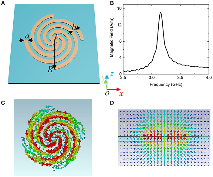
Figure 1. (A) Schematic of the metallic spiral structure. (B) Magnetic field amplitude intensity detected at the center of the resonator. (C) Current distribution at z = 0. (D) Magnetic field vectors at x = 0.
As mentioned in Ref. [11], the spiral textured two-dimensional (2D) metal cylinder can be described by the effective medium theoretical model. Following this homogeneous metamaterial approximation, the geometric parameters of the MSS determine the effective permittivity and permeability, which are related to the spoof LSP resonances. Although the physical characteristics of the plasmonic metamaterial antenna is different from the textured 2D cylinder, the analytical model can direct the manipulation of spoof LSP resonances in the antenna in some sense. In order to study the relationship between the magnetic plasmonic resonance frequencies with the geometric parameters, numerical simulations were carried out using a CST Microwave Studio. When the radius R = 9.17 mm, the magnetic resonance frequencies for various filling factor a/b is presented in Figure 2A. As can be seen, the frequency is dependent on the filling factor variation, which decreases as the factor reduces. Figure 2B explores the dependence on radius R of the magnetic plasmonic resonance characteristics as a/b = 1.25. At small R = 7 mm, the frequency for the magnetic spoof LSP resonance is 5.5 GHz, which is the highest. The magnetic mode shifts toward 2.2 GHz as R increase to 11 mm. Figure 2C further gives the resonance frequency as a function of the inner radius r with a/b = 1.25, R = 9.17 mm, in which we see that the resonance frequency increases from about 3.14 to 4.32 GHz as r increases from 0.5 to 5 mm. More interesting, we found that the bigger the radius r the more effect is had on the resonance frequency. This can be attributed to the fact that the resonance frequency is related on the length of spiral grooves. Moreover, a larger radius r will result in greater variation in the length of spiral grooves.
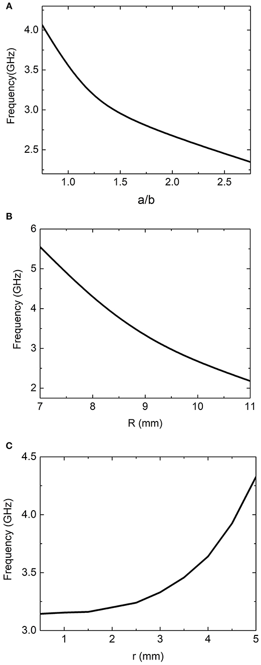
Figure 2. The resonance frequencies of spoof magnetic plasmon modes as a function of the filling factor a/b (A), outer radius R (B) and inner radius r (C).
In this case, we can manipulate the operating frequency of the magnetic resonance by adjusting the antenna structure parameters. An appropriate choice of the structure parameters allows the working frequency of plasmonic metamaterial antenna to meet different practical requests. More interestingly, the antenna with R = 9 mm corresponds to the resonance wavelength of about 100 mm. It is evident that the resonance wavelength of spoof magnetic LSP is much larger than the antenna size, indicating our design is a subwavelength antenna.
SSPPs Groundless Feeding Line
In order to excite the spoof magnetic LSP mode in antenna effectively and eliminate the ground impacts on the field, we consider a SSPPs waveguide. The proposed groundless SSPPs waveguide is configured by a meander line, as shown in Figure 3A. The waveguide is printed onto a piece of FR4 substrate [relative permittivity of 2.2(1 + i0.003)] with thickness of 1.5 mm. Here, the SSPPs is fed by a coplanar waveguide (CPW). Therefore, the whole structure consists of two parts: a mode conversion and momentum matching section, and a SSPP transmission line. The dimensions gc and wc labeled in the left inset of Figure 3A are designed to achieve 50 Ω input impedance, in which gc = 0.2 mm is the width of the symmetrical slots, and wc = 3 mm is the width of the inner conductor line. As shown in Figure 3A, the convertor section comprises two symmetrically flared ground and an array of 10 distinctive “S” shape unit cells with their depth gradually increasing. The flared ground is set an exponential equation , where , , and the exponent parameter is α = 0.04. The right inset of Figure 3A gives the sketch of SSPPs transmission line. The cycle of meander is set as p = 9 mm, while the groove depth and width are g = 12 and d = 2.2 mm, respectively. The dispersion curve of SSPPs unit cell is calculated and plotted in the inset of Figure 3B, which is analogous to the conventional SPPs in optical range. In this regard, the surface wave modes in the meander line is SSPPs slow wave mode. By the convertor section, a gradual mode conversion and momentum matching can be obtained between the guided wave in CPW and SSPPs modes. To confirm the transmission performance of the converter and SSPPs waveguide, we simulated the S parameters by CST Microwave Studio.
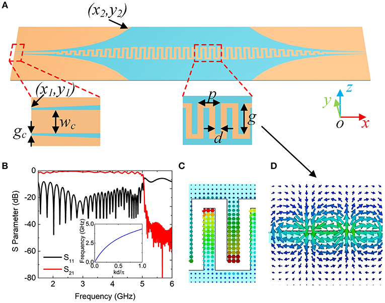
Figure 3. (A) Proposed SSPPs waveguide composed of S-shaped unit cells connected to two CPW lines through the mode converter. The mode converter is composed of unit cells with gradually increasing groove depth and the flared ground plane. (B) Simulated transmission and reflection from the designed SSPPs waveguide solved by CST Microwave Studio. Inset: dispersion curves of the SSPPs cell calculated by eigen-mode; Magnetic field distributions at two cutting planes z = 0 (C) and y = 0 (D).
The simulated transmittance and reflectance spectra are presented in Figure 3B, in which the high transmission and low reflection are clearly observed in 1.5–5 GHz range. The suddenly dropped S21 at 5 GHz denotes the cut-off frequency of this SSPPs waveguide. According to the numerical calculation results in Figure 2, the designed SSPPs waveguide's operating frequency range can cover the resonance frequencies of the LSP resonance in MSS antenna. Figure 3C illustrates magnetic field vectors of SSPPs waveguide in the cutting plane z = 0 mm, while Figure 3D shows the magnetic field distribution in the cross-section y = 0 mm. From the distributions, we find that the magnetic field is located in the grooves and is perpendicular to the structure.
Discussion of Antenna Performance
As mentioned in the above discussions, the equivalent magnetic dipole in antenna is vertical. For the sake of effective exciting, the magnetic fields of both spoof magnetic plasmonic mode in antenna and the SSSPs mode in plasmonic waveguide should be parallel to each other. In addition, the antenna and SSPP waveguide should be overlapped with each other. To this end, we consider the structure depicted schematically in Figure 4A. The proposed SSPPs waveguide is cut. The SSPPs waveguide and the antenna disk are printed on the bottom and top side of the FR4 substrate with 1.5 mm thickness, respectively. The geometry parameters of the antenna are set as inner radius r = 1 mm, R = 9.17 mm, a = 1.1 mm, b = 0.88 mm. And the period of meander is p = 9 mm, the groove depth g = 12 mm, and width d = 2.2 mm. In this case, the antenna without the feeding SSPPs waveguide resonates at 3.16 GHz at the spoof magnetic LSP resonance mode.
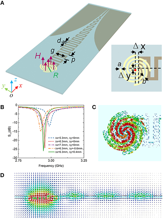
Figure 4. (A) Plasmonic metamaterial antenna fed with the proposed SSPPs waveguide configuration. (B) S-parameter results for various MSS disk locations. (C) The simulated current distributions of the spoof plasmonic resonance mode and the feeding end. (D) Magnetic field vector distributions at cutting plane y = 0.
Δx and Δy can be used to adjust the location of antennas, which impacts on the excitation efficiency. By optimizing the dimensions of Δx and Δy to obtain the best performance of the lowest reflection, their optimized values are 6.3 and 0.4 mm, respectively, as plotted in Figure 4B. Figure 4C shows the surface current distribution in the MSS disk at 2.9 GHz. The resulting surface current exhibits a loop, which resembles the currents in the isolate antenna without the SSPPs feeding line (Figure 1B). We also checked the magnetic field vectors in the cross-section y = 0 in Figure 4D, in which the magnetic fields transport in SSPPs waveguide and excite magnetic resonances in the antenna. The magnetic fields in antenna act like a magnetic dipole mode. The results demonstrate that the spoof magnetic surface plasmon resonance in antenna can be excited by the SSPPs waveguide effectively. Here, the spoof plasmonic antenna with the feeding configuration works at 2.9 GHz, while the resonance frequency of an isolated antenna is 3.15 GHz. The resonance frequency in the presence of the feeding line is shifted by 6.7%. The frequency deviation comes from the metal meander line, which is close to the antenna, and affects the field distribution of the resonance mode slightly.
Please note that our design has some positive features, such as deep subwavelength size and low profile. However, the high Q factor of the spoof LSP resonance limits the bandwidth of the antenna. When we apply the antenna, we need to consider the balance between the size and the bandwidth.
Fabrication and Experiment
According to the parameters given before, a prototype of the proposed spoof plasmonic antenna was fabricated and measured. Two photographs of top view and bottom view of the fabricated prototype are presented in Figure 5A. Figure 5B depicts the simulated and measured reflection spectrums, which are in good agreement. In order to confirm the far-field behaviors of the antenna, the simulated and measured far-field patterns at resonance frequency are compared in Figure 6.
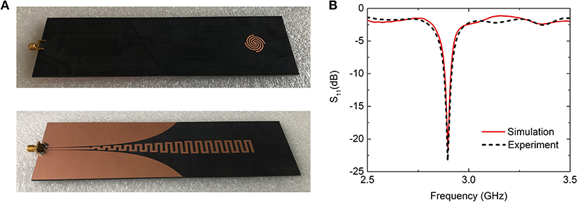
Figure 5. (A) Photographs of the fabricated SSPPs waveguide feeding configuration and the plasmonic metamaterial antenna. (B) Comparison of scattering parameter results between simulation and experiment results for the antenna fed with the proposed SSPPs waveguide.
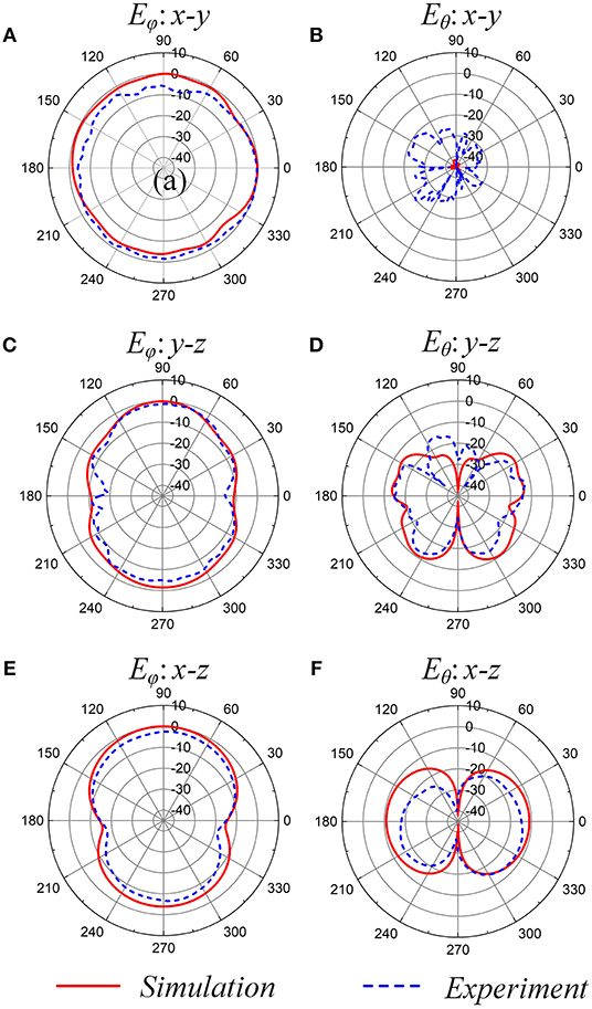
Figure 6. Comparison of the far-field radiation patterns from the antenna between simulations and measurements. (A) Eϕ in x–y plane. (B) Eθ in x–y plane. (C) Eϕ in x–z plane. (D) Eθ in y–z plane. (E) Eϕ in y–z plane. (F) Eθ in x–z plane.
Figure 6 illustrates the Eθ and Eϕ radiation patterns in three principal planes, x-y, y-z, and x-z plane. According to Figure 1B, the surface currents of magnetic mode circulate along the azimuthal direction, which result in the polarization of the far field along the azimuthal direction (ϕ). As expected, the magnitudes of the copolarized component (Eϕ) is much higher than the cross-polarization (Eθ) of the radiated field in Figure 6. As can be seen from the Eϕ radiation patterns in the azimuth plane (x-y plane), the antenna has an omnidirectional radiation pattern in Figure 6A. The radiation patterns at the elevation plane (y-z and x-z plane) show a quasi-eight shape in Figures 6C,E, respectively. The radiation patterns of the proposed spoof plasmonic antenna are very close to that of an ideal magnetic dipole. As expected, the radiation patterns cover both the upper and lower space equally. The slight asymmetric pattern might be due to the feed line. The SSPPs waveguide may slightly affect the current distribution in the antenna and shield the radiation of the antenna.
The simulation results for the total efficiency with lossless substrate and perfect PEC is 94%. The simulation results for the total efficiency for the lossy substrate and cooper loss is 94%. It exhibits a maximum radiation realized gain of 3.15 dBi in the x-y plane.
Measurements also present similar radiation patterns as those plotted here. The patterns show accurate agreement, except for the Eθ in the x-y plane. In Figure 6B, the cross-polarization levels of the simulated and measured results are −20 and −40 dB, respectively. Both of them are <-20 dB, whose difference in liner value is extremely tiny. The difference between the two results can be caused by the dielectric constant tolerance of the substrate and the change in the substrate thickness during the fabrication process.
Conclusion
In conclusion, we numerically and experimentally demonstrate horizontally polarized omnidirectional radiation using spoof surface plasmons metamaterial. The spoof plasmonic antenna shown here can be treated as a homogeneous effective medium. The magnetic spoof LSP of the metamaterial act as a magnetic dipole, which is used to achieve a horizontally polarized omnidirectional radiation pattern. A SSPPs transmission line is used to feed the antenna. We also verify through numerical simulations and experiments that the compact and subwavelength design works as predicted, showing its high suitability and usability with further practical applications. Moreover, since the design is analogous to its optical antenna counterpart, it will provide additional understanding from microwave antennas to optical antennas. Our results will enable many potential applications including, but not limited to, microwave and RF antennas, as well as terahertz beam generators.
Data Availability Statement
All datasets generated for this study are included in the article/supplementary material.
Author Contributions
ZL was the leader of the work and responsible for the main of experiment and paper writing. XW, BGC, BC, and YP were responsible for single step of the fabrication process. GL contributed to the modification and suggestion in this paper.
Funding
This work was supported in part by the National Natural Science Foundation of China (Grants Nos. 61701151, 61722107, and 61701145), the China Scholarship Council (CSC) (Grant CSC No. 201808330064), and Foundation of State Key Laboratory of Millimeter Waves, Southeast University, China, under Grant (No. K202009).
Conflict of Interest
The authors declare that the research was conducted in the absence of any commercial or financial relationships that could be construed as a potential conflict of interest.
References
1. Maier SA. Plasmonics: Fundamentals and Applications. New York, NY: Springer (2007). doi: 10.1007/0-387-37825-1
2. Park QH. Optical antennas and plasmonics. Contemp Phy. (2009) 50:407–23. doi: 10.1080/00107510902745611
3. Choosak K, Silapunt R, Mohammed WS. Study of localized surface plasmon properties on metallic nano-rods towards optical antennas. In: 2014 International Electrical Engineering Congress (iEECON) (Chonburi: IEEE) (2014). p. 1–4. doi: 10.1109/iEECON.2014.6925936
4. Kausar A, Reza A, Latef T, Ullah M, Karim M. Optical nano antennas: state of the art, scope and challenges as a biosensor along with human exposure to nano-toxicology. Sensors. (2015) 15:8787–831. doi: 10.3390/s150408787
5. Bharadwaj P, Deutsch B, Novotny L. Optical antennas. Adv Opt Photon. (2009) 1:438. doi: 10.1364/AOP.1.000438
6. Kumar A. Optical Nano-Antennas: Fabrication, Characterization and Applications. Illinois : University of Illinois at Urbana-Champaign (2011) 93.
8. Pors A, Moreno E, Martin-Moreno L, Pendry JB, Garcia-Vidal FJ. Localized spoof plasmons arise while texturing closed surfaces. Phys Rev Lett. (2012) 108:223905. doi: 10.1103/PhysRevLett.108.223905
9. Shen X, Cui TJ. Ultrathin plasmonic metamaterial for spoof localized surface plasmons. Laser Photonics Rev. (2014) 8:137–45. doi: 10.1002/lpor.201300144
10. Huidobro PA, Shen X, Cuerda J, Moreno E, Martin-Moreno L, Garcia-Vidal FJ, et al. Magnetic localized surface plasmons. Phys Rev X. (2014) 4:021003. doi: 10.1109/MetaMaterials.2014.6948552
11. Liao Z, Fernández-Domínguez AI, Zhang J, Maier SA, Cui TJ, Luo Y. Homogenous metamaterial description of localized spoof plasmons in spiral geometries. ACS Photonics. (2016) 3:1768–75. doi: 10.1021/acsphotonics.6b00488
12. Liao Z, Luo GQ, Cai BG, Pan BC, Cao WH. Subwavelength negative-index waveguiding enabled by coupled spoof magnetic localized surface plasmons. Photonics Res. (2019) 7:274. doi: 10.1364/PRJ.7.000274
13. Liao Z, Luo GQ, Ma HF, Pan BC, Cai BG, Yu YF, et al. Localized surface magnetic modes propagating along a chain of connected subwavelength metamaterial resonators. Phys Rev Appl. (2018) 10:034054. doi: 10.1103/PhysRevApplied.10.034054
14. Zhang Y, Zhou YJ, Cai J, Jiang JH. Amplification of spoof localized surface plasmons on active plasmonic metamaterials. J Phys D Appl Phys. (2018) 51:295304. doi: 10.1088/1361-6463/aaca25
15. Zhou YJ, Li QY, Zhao HZ, Cui TJ. Gain-Assisted active spoof plasmonic fano resonance for high-resolution sensing of glucose aqueous solutions. Adv Mater Technol. (2019) 5:1900767. doi: 10.1002/admt.201900767
16. Gao F, Gao Z, Shi X, Yang Z, Lin X, Xu H, et al. Probing topological protection using a designer surface plasmon structure. Nat Commun. (2016) 7:1–9. doi: 10.1038/ncomms11619
17. Zhang J, Liao Z, Luo Y, Shen X, Maier SA, Cui TJ. Spoof plasmon hybridization: Spoof plasmon hybridization. Laser Photonics Rev. (2017) 11:1600191. doi: 10.1002/lpor.201600191
18. Xiao S, He Q, Huang X, Tang S, Zhou L. Enhancement of light-matter interactions in slow-wave metasurfaces. Phys Rev B. (2012) 85:085125. doi: 10.1103/PhysRevB.85.085125
19. Guo H, Lin J, Qiu M, Tian J, Wang Q, Li Y, et al. Flat optical transparent window: mechanism and realization based on metasurfaces. J Phys D Appl Phys. (2018) 51:074001. doi: 10.1088/1361-6463/aaa451
20. Yang B, Liu T, Guo H, Xiao S, Zhou L. High-performance meta-devices based on multilayer meta-atoms: interplay between the number of layers and phase coverage. Sci Bull. (2019) 64:823–35. doi: 10.1016/j.scib.2019.05.028
21. Shen X, Cui TJ, Martin-Cano D, Garcia-Vidal FJ. Conformal surface plasmons propagating on ultrathin and flexible films. Proc Natl Acad Sci USA. (2013) 110:40–5. doi: 10.1073/pnas.1210417110
22. Kianinejad A, Chen ZN, Qiu C. Design and modeling of spoof surface plasmon modes-based microwave slow-wave transmission line. IEEE Trans Micro Theory Tech. (2015) 63:1817–25. doi: 10.1109/TMTT.2015.2422694
23. Kianinejad A, Chen ZN, Qiu C. Full modeling, loss reduction, and mutual coupling control of spoof surface plasmon-based meander slow wave transmission lines. IEEE Trans Micro Theory Tech. (2018) 66:3764–72. doi: 10.1109/TMTT.2018.2841857
24. Kianinejad A, Chen ZN, Qiu C. Low-Loss spoof surface plasmon slow-wave transmission lines with compact transition and high isolation. IEEE Trans Micro Theory Tech. (2016) 64:3078–86. doi: 10.1109/TMTT.2016.2604807
25. Chizhik D, Ling J, Valenzuela RA. The effect of electric field polarization on indoor propagation. In: IEEE 1998 International Conference on Universal Personal Communications ICUPC '98. Florence (1998) 1:459–462.
26. Soras C, Karaboikis M, Tsachtsiris G, Makios V. Analysis and design of an inverted-F antenna printed on a PCMCIA card for the 2.4 GHz ISM band. IEEE Antenn Propag M. (2002) 44:37–44. doi: 10.1109/74.997891
27. Wei K, Zhang Z, Feng Z, Iskander MF. Periodic leaky-wave antenna array with horizontally polarized omnidirectional pattern. IEEE Trans Antenn Propag. (2012) 60:3165–73. doi: 10.1109/TAP.2012.2196930
28. Zhang Y, Zhang Z, Li Y, Feng Z. A dual-loop antenna in a cage structure for horizontally polarized omnidirectional pattern. IEEE Antenn Wirel Propag Lett. (2013) 12:1252–5. doi: 10.1109/LAWP.2013.2283543
29. Yu Y, Jolani F, Chen Z. A wideband omnidirectional horizontally polarized antenna for 4G LTE applications. IEEE Antenn Wirel Propag Lett. (2013) 12:686–9. doi: 10.1109/LAWP.2013.2264545
30. Quan XL, Li R, Wang JY, Cui YH. Development of a broadband horizontally polarized omnidirectional planar antenna and its array for base stations. Prog Electromagn Res. (2012) 128:441–56. doi: 10.2528/PIER12042405
Keywords: metamaterials, spoof surface plasmons, spoof localized surface plasmons, omnidirectional antennas, magnetic resonance
Citation: Liao Z, Luo GQ, Wu XY, Cai BG, Cao Pan B and Pan YJ (2020) A Horizontally Polarized Omnidirectional Antenna Based on Spoof Surface Plasmons. Front. Phys. 8:53. doi: 10.3389/fphy.2020.00053
Received: 15 January 2020; Accepted: 20 February 2020;
Published: 24 March 2020.
Edited by:
Lin Chen, University of Shanghai for Science and Technology, ChinaReviewed by:
Shiyi Xiao, Shanghai University, ChinaJunichi Fujikata, Photonics Electronics Technology Research Association, Japan
Copyright © 2020 Liao, Luo, Wu, Cai, Cao Pan and Pan. This is an open-access article distributed under the terms of the Creative Commons Attribution License (CC BY). The use, distribution or reproduction in other forums is permitted, provided the original author(s) and the copyright owner(s) are credited and that the original publication in this journal is cited, in accordance with accepted academic practice. No use, distribution or reproduction is permitted which does not comply with these terms.
*Correspondence: Guo Qing Luo, bHVvZ3VvcWluZ0BoZHUuZWR1LmNu