Abstract
The biological world is composed of folded linear molecules of bewildering topological complexity and diversity. The topology of folded biomolecules such as proteins and ribonucleic acids is often subject to change during biological processes. Despite intense research, we lack a solid mathematical framework that summarizes these operations in a principled manner. Circuit topology, which formalizes the arrangements of intramolecular contacts, serves as a general mathematical framework to analyze the topological characteristics of folded linear molecules. In this work, we translate familiar molecular operations in biology, such as duplication, permutation, and elimination of contacts, into the language of circuit topology. We show that for such operations there are corresponding matrix representations as well as basic rules that serve as a foundation for understanding these operations within the context of a coherent algebraic framework. We present several biological examples and provide a simple computational framework for creating and analyzing the circuit diagrams of proteins and nucleic acids. We expect our study and future developments in this direction to facilitate a deeper understanding of natural molecular processes and to provide guidance to engineers for generating complex polymeric materials.
1. Introduction
Topology is a mathematical concept that refers to specific properties of objects that remain invariant under continuous operations like stretching, bending, or shrinking [1]. Objects that transform to each other by such continuous deformations fall into the same topological class. For instance, circles and triangles are topologically alike since they can interconvert by bending or stretching. There is a close relationship between the functional and physical properties of molecular structures and their topological features [2, 3]. Moreover, topology provides elementary rules that help us to engineer molecules in a desired way and to synthesize new structures [4–6]. Emergent properties may be seen in such synthetic molecules that have no counterpart in the biochemical world [7, 8].
In chemistry there are general frameworks, such as group theory, that aid in investigating the topological and geometrical properties of molecules. In biology, however, we lack similar frameworks. The diversity and complexity of biological molecules make it difficult to reduce the structural and functional properties of molecules to simple rules of symmetry. Consequently, creating a topological language for biochemistry and biochemical engineering is an interesting scientific challenge. Such a framework would be a powerful tool for unifying the diversity of molecules within a coherent closed theory. Many applications can be envisioned, as the relation between topology and biomolecular function or dysfunction has been addressed frequently in health and disease [9, 10]. Topological approaches have already been implemented in powerful machine learning algorithms to correctly predict protein-ligand binding affinities, mutation induced globular protein folding free energy changes, and mutation induced membrane protein folding free energy changes [11, 12].
Biological circuit topology is a mathematical approach that describes the relationships between intramolecular contacts within a folded molecule [13–20]. In this framework, pairwise relations between contacts can be defined using the logic rules of set theory [13, 14]. Irrespective of the kind of molecule or its complexity, two contacts may have one of a few general symmetry relations with one another. For binary contacts, they might be in parallel, in series, or in cross arrangement, or in corresponding concerted arrangements if two contacts share a site. Figure 1 demonstrates these arrangements and the associated matrices showing connectivity of sites. Completeness of these relations can be proved [13], and they can be considered as necessary and sufficient to describe the topology of folded molecules (formed by di- or multi-valent contacts). Circuit topology forms a set of rules that can be used to find unknown topological relations between contacts from known relations. In this approach, topology is represented in matrix forms, and equivalent topologies are inferred from identical matrix representations. Biological circuit topology makes it possible to determine the topology of a more complex molecule resulting from the combination of simpler molecules. The folding rates and number of unfolding paths of a macromolecule can be estimated using circuit topology rules [14].
Figure 1
The circuit topology of biomolecules is subject to changes during folding/unfolding and biochemical reactions as well as during evolution. Here we ask how the topology changes upon basic molecular operations such as permutation of contacts, duplication, or elimination. We develop a simple algebraic formalism to describe the effect of these operations. Briefly, each topological state can be described by a connectivity matrix, and topological changes can be described as transformations of the matrix, for which linear algebra already provides all the necessary tools. We show that the outcome of operations on molecules with complex topologies can be readily predicted from this approach. Our results are relevant to understanding the evolution and structural similarities of proteins and other biological molecules, and they may help provide a guideline to molecular engineers interested in engineering folded molecules, active materials, and smart structures.
2. Circuit Topology and Molecular Operations
We will introduce here a new way of describing both the topological state of a folded linear polymer and molecular operations on the structure. Both the topological state and changes to this state are represented using permutation matrices (representations of Sn) and are connected with the well known tools of matrix multiplication.
2.1. Circuit Topology
In the following, we redefine basic concepts of circuit topology to allow for the ability to use simple algebraic operations, rather than relying on combinatorical algorithms. In this generalized approach, we show that any structure of a linear molecule can be uniquely represented by a permutation matrix and a vector d, called the connectivity matrix and backbone, respectively.
A mathematic permutation is an exchange of elements. The abstract map is often denoted with a greek letter (we will often use π) and maps an integer onto another integer π(i) = j. If and only if a permutation exchanges only two elements it is called a transposition. The abstract permutation can be represented by a permutation matrix. A permutation matrix exchanges elements of a vector according to the permutation. It has only entries of 1 and 0, and the sum of each row and the sum of each column is 1. In the case of circuit topology not any permutation matrix can be used. First of all, must be symmetric, i.e., it consists only of commutating transpositions. The matrix
for example, exchanges element 1 with 2 and leaves the element 3 unchanged [it is often represented as (12) (3) or (12)]. In biological circuit topology this represents a connection between the element 1 and 2 of the backbone d.
The backbone d is a vector that holds the information of the underlying molecular structure. It may consist of the indices of all the aminoacids in a protein or nucleotides in a DNA sequence, or it can be the length of the string/chain up to a particular point di. d need not be complete (i.e., it need not contain the whole array of indices), for example d = (2, 5, 20, 21) is a valid backbone vector. In addition the values need not be unique. This means e.g., d = (1, 2, 2, 3) is also acceptable and in some cases even required. If the elements of d are distances, then di can be any real number, e.g., d = (1.23, 1.938, 5.392). If an element is not exchanged by the connectivity matrix (for example the element 3 in Equation 1) then it can safely be eliminated from the representation without changing the state of the molecule:
When changing the pair in this way, the molecule itself is not changed, but the representation is minimalized. A more detailed discussion on transformations can be found in the next section.
The pair defines a state of a linear molecule (e.g., protein, DNA), where d defines the bonding sites and the connectivity of these bonding sites. Figure 1 shows a two-bond system with all possible relations. The possible relations are series (S), cross (X), and parallel (P). Two special connectivity relations (concerted parallel and concerted series) are discussed below. Note that only P is non-reflexive and has an inverse relation P−1, for more detailed information see Mashaghi et al. [13].
For most of the connectivity relations the connectivity map is identical to the contact map, however two special connectivity relations lead to different matrices: concerted parallel (CP) and concerted series (CS). For a contact with residue 1 and 2 and contact 2 with 3 (CS) the contact map is given by
This is however not a permutation matrix and therefore forbidden as a connectivity matrix. In order to represent this system in the circuit topology framework d must contain the contact site 2 twice, one of which being in contact with 1 and the other with 3. One might think of it as fictionally separating the site 2 into two separate and distinct sites, 2 and 2', forming the connection and then bringing them together by 2 = 2′. The correct connectivity matrix and backbone for CS are therefore
Figure 1 also shows the correct representation for CP.
The demand for uniqueness requires additional restrictions on d and . If d only contains each value once, then ordering is sufficient for uniqueness; however if this is not the case, then several equivalent arrangements of d will lead to different (for example, swapping index 2 with 3 in Equation 4). We define the ordered state therefore as follows: for all i and j with i < j we have di ≤ dj and if di = dj then it follows that π(i) < π(j), where π is the permutation that is represented by . For example,
is the same state as in Equation (4), however for d2 = d3 but 4 = π(2) ≮ π(3) = 1, therefore the only correct representation is in Equation (4).
In addition we also impose the rule that there can not be contact between identical sites and that any bond can occur at most once. This means that a contact like
is never allowed. With these restriction (d is ordered, is ordered for di = dj and no contacts between equal sites) is said to be reduced. This gives uniqueness and the ordering is consistent with previously defined orders [20]. For the complete proof see Supplementary Information.
Finally, we introduce the relations matrix [13]. The relations matrix is a n × n-matrix that contains the relation between bonds, where n is the number of contacts. The relations are the known X, P, P−1, S…. This representation is mostly for the purpose of display, because it is smaller than and the relation between bonds can immediately be read out.
Finally we will propose a simple way of comparing different states:
identical: d = d′ and
partially equivalent: and both d and d′ are ordered in a similar way, where and d exclude any elements without connections.
non-equivalent: otherwise.
The description of the topological state of a protein using the pair provides a powerful tool to perform transformations using algebraic operations which are well-known and readily available. The various types of transformations are discussed in the next section.
2.2. Molecular Operations
2.2.1. General
A molecular operation is any map such that . We can loosely classify these operations as rearrangements or as operations where the topological state of the molecule is changed (molecular operation), or as a combination of both types. Clearly, we are interested in the molecular operations where both the pre-image and the image are ordered and reduced. The restriction is necessary because it will conveniently directly lead to a unique map that describes the change explicitly [without any additional combinatorial (re)arrangements]. We first describe three types of transformations, that give the transformations a clear interpretation.
The first set of transformations are type-0 transformations. Type-0 deformation do not change the topological state of the molecule, and form a group that consist of reordering, extending and reducing of d.
The first subgroup consists of the ordering transformations. If d is not ordered, then one can order it using a permutation matrix O, which swaps the corresponding elements in d. This must lead to a change in for the system to remain unchanged. The change is described by . In summary, the pair and describe the same state, but are different representations. Visually it can be thought as relabeling the residues in a protein, without changing the sequence or the connectivity.
For example, we consider the state where residue 1 with 2, as well as residue 3 and 4 share a connection. The system is described by the following and d
d is however not ordered, which might lead to confusion, as S could be mistaken for a X state. Redordering demand that the element d2 and d3 are exchanged. The corresponding permutation matrix O is given by
and we can calculate the transformed d′ and
The pair clearly describe the same state, however the fact that d is ordered, makes it easier to interpret and prevents reading errors. This is especially of importance when transformations of other types (see below) produce an unordered d that might be not noticed.
The other group of transformations of type-0 increase or decrease the length of d but do not change the topological state of molecule. The reduction, for example, can be used to eliminate unbound contact sites, to give a smaller still containing all the necessary information. The extension does the opposite. It may, for instance, add another entry in d so that additional bonds can be formed, or it may reintroduce whole blocks of the protein which were disregarded because they might not have been of importance. An example for a type-0 transformation is given by
The molecular operations that literally change the molecule can be separated into (i) transformations that change the contacts (Type I), and (ii) transformations that change the backbone (Type II).
Type-I transformations lead to a change of the contacts. This means that either new contacts are formed (creation), existing contacts are broken (annihilation), or both. Both operations are performed with the same operator, which is a permutation matrix which transposes the elements that are affected. The operator matrix is multiplied to the matrix, but one must be careful to perform the annihilation(s) first. In some cases the final state is unordered and must be reordered again. Reordering is a type-0 transformation and requires . For the simple case of where the bond (23) is broken and a bond (12) is created we use
If, on the other hand, the initial and final states are known the total transformation matrix can directly be calculated with . This also gives the shortest path from to because any transposition is its own inverse. For example, the transformation (12)(34)(56) ↦ (12)(36) will give T = (12)(36) · (12)(34)(56) = (12)(12)(34)(56)(36) = (12)(12)(36)(34)(56) = (36)(34)(56). This shows that at the most three operations need to be performed. (The same result would be obtained using matrices).
As mentioned already, if the resulting state is unordered, it must be reordered again. Otherwise operations might arise that do not actually change the system. This is only the case if d contains a value multiple times. For example, consider d = (1, 2, 2) and . Annihilation of (12) and creation of (13) would give . This is not ordered however because for i = 2 < 3 = j will give d2 = 2 = d3 but π(2) = 2 > π(3) = 1 which is contrary to the assumption of being ordered. Reordering will give , so the same as the initial state. The transformation described is therefore actually only the unity map.
Type-II transformations: these types of transformation literally change the backbone of the molecule. The map acts therefore mostly on d which afterwards must be ordered again. For simple categories as below, simple transformations are readily available but in theory almost any map on d is possible. For example when a part is cut out reattached then: d = (1, 2, 3, 4) ↦ d = (1, 2, 4, 3). This d however has to be reordered with O = (34) and in turn also changes.
The biological difference of type-I and type-II is clear, however from a mathematical perspective they may be equivalent. As long as the same resulting state appears the map is mathematically identical and interchangeable. If a type-I and a type-II transformation are equivalent, and one might be much more complex to perform, it can easily be reproduced with the other transformation. This is comparable to coordinate transformation: one can either rotate a point in space with respect to a fixed coordinate system or rotate the coordinates and leave the point fixed. Both transformations yield the same result but the mathematical procedure is different. The same can be said about type-I and type-II transformations.
In the following, we redefine the most important molecular operations using the logic of circuit topology. Specifically, we treat circular and standard permutation, inversion, duplication, and elimination. These operations are of much relevance to biomolecular evolution, conformational dynamics and folding, and structural comparison. We discuss these operations in detail in the context of biological circuit topology, and we demonstrate specific applications to the analysis of protein and RNA structure. In the Supplementary Information, we present the complete mathematical framework, citing specific examples in the main text.
2.2.2. Permutation
Permutation changes contacts through restructuring or reordering, resulting in a new structure with different connectivity. Mathematically it can either be a type-I or type-II molecular operation, it is however simpler to treat this transformation as a type-II molecular operation. This does not necessarily imply that biologically it is a type-II transformation, it is just simpler to calculate it as such. That such changes have relevance to biomolecules is well-established, and algorithmic approaches have even been proposed for the detection of permutation [21–23]. Here, we focus on two types of permutation, namely standard permutation and circular permutation.
2.2.2.1. Standard permutation
In standard permutation, two sites are swapped (replaced with each other), while preserving other aspects of connectivity. Figure 2A demonstrates a standard permutation in which sites i and m are swapped, thereby transforming a cross relation into a series relation. Following the specific example shown in Figure 2A, permutation takes place between the middle sites of (1) and (3) which are in cross arrangement. The resulting symmetry of the two contacts in the new molecule will be series. The symmetry relations of contact (2) and other contacts remain unchanged, i.e., in parallel with (1) and in series with (2) as before.
Figure 2
The matrix formalism for standard permutation is described in the previous section. In the case of the example discussed above, the original arrangement of contacts is given by the connectivity matrix (which in this instance is identical to the contact map).
For instance, the first site is bonded to the fifth, and so there is a 1 at column 5 of the first row, and so on. There are three contacts, each containing unique sites, so the size of the contact matrix is 6 × 6, and the matrix is of course symmetric (if 2 contacts 3, then 3 will contact 2). By definition, no site is in contact with itself. The permutation matrix for exchange of sites 4 and 5 is given by
Then we have which is equal to
Table 1 summarizes all possible results of standard permutation for a system containing two contacts. For instance, a cross, series, or parallel relation can be converted into any other of the three relations by application of the appropriate transformation. In the context of biological molecules, two contacts may share a contact site, resulting in concerted parallel (CP) or concerted series (CS) relations, as shown in Figure 2B. The effect of standard permutation on these relations is summarized in Table 2, where each “site” represent, for instance, a secondary structural element or nucleotide. For two contacts, there are four sites: two adjacent inner sites and two outer sites; sites may either be neighboring or non-neighboring.
Table 1
| Init. | Middle | Outer | Mid., term. N. | Mid., term. N.N. |
|---|---|---|---|---|
| P | P | P | X | S |
| X | S | S | P | X |
| S | X | X | S | P |
Result of standard permutation between each pair of sites within two contacts.
Contacts begin in parallel (P), cross (X), or series (S) relation. Shown are the initial symmetry and result of permutation between middle sites, outer sites, middle and terminal neighboring sites, and middle and terminal non-neighboring sites.
Table 2
| Init. symmetry | Mid., shared | Mid., unshared | Term. |
|---|---|---|---|
| CP | CS | CP | CP |
| CS | N/A | CP | CS |
Result of standard permutation, starting from concerted parallel (CP) or concerted series (CS) relations.
The shared terminal site refers to the site common to the two contacts in concerted parallel relation.
Inversion can be understood in terms of standard permutation operations and is discussed in the Supplementary Information.
We further illustrate the concept of standard permutation using an example from protein structure. For details of the computational approach for diagram generation (see Figure S2). In this and other examples, we assume some familiarity with biomolecular structure; for readers less familiar with this field, excellent introductions can be found in references [24, 25].
The simple circuit diagram of an eight-stranded beta barrel protein is shown in Figure 3A (color added to help visualize the effect of permutation), with the protein structure shown in Figure 3C. Each strand is connected to the next strand in the sequence, and the last strand is connected to the first. Note that here we depict reduced diagrams, with each beta strand corresponding to a node of the diagram. A standard permutation of sites 4 and 8 of the beta barrel diagram yields the greek key barrel (Figure 3B, protein structure shown in Figure 3D). Permutation clearly changes the contact map (Figures 3E,F) and also affects the map of relations (Figures 3G,H), increasing the number of parallel and cross relations relative to series. Our framework thus illustrates detailed properties of a structural relation between two well-known protein folds.
Figure 3
2.2.2.2. Circular permutation
In circular permutation, the two ends of the molecule are joined, and a single cut is made elsewhere in the molecule, resulting in a topology with identical contacts, but, in general, different relations between them. For a molecule with two contacts, this can be pictured easily as shown in Figure 2C. Hence, circular permutation can transform a parallel relation to a series relation and vice versa depending on the position of the ending point of circulation. The resulting symmetry ultimately depends on the location of this ending point with respect to the positions of the contact sites. Topology can be determined according to the following rules, using the points-on-a-line visualization of Figures 1, 2A,B. If the two contacts are initially in series, then placing the new endpoint within the interval of either contact leads to parallel symmetry; otherwise series symmetry is preserved. If the two contacts are in parallel, then placing the endpoint within the interval of one contact but not the other leads to series symmetry; otherwise parallel symmetry results. CP and CS relations can be treated as parallel and series above. If the two contacts are in cross relation, any circular permutation will result in cross relation.
The example in Figure 2C contains just four contact sites. The original matrix, depicting two contacts in parallel is
and the permutation matrix for a single clockwise rotation of the endpoint is
Then is
Standard and circular permutation are relevant to protein evolution [26, 27], as discussed in Figure S3 and the corresponding discussion.
2.2.3. Elimination
Elimination is the deletion of a contact or set of contacts. Elimination does not change the symmetry relations between remaining contacts. Figure 4 shows a simple example, where we begin with four contacts and contact (4) is eliminated. Matrix representations before and after elimination are depicted. To find the final representation after elimination we omit the row and the column that (4) belongs to. The matrix framework for elimination can be found in the Supplementary Information.
Figure 4
We illustrate elimination in Figure 5, showing that elimination of four contacts within the eight-stranded beta barrel topology leads to the fundamental topology of tRNA. Figures 5A,B show that the basic tRNA topology (apparent from visual inspection of hydrogen bonding patterns) can be deduced by starting from the beta barrel topology and introducing four eliminations, shown as dotted lines in Figure 5A. This structure contains no concerted relations, and in fact it is possible to draw a simple analogy to electronic circuits, with the topologically equivalent capacitor schematic depicted in the inset of Figure 5B. Figure 5C confirms that contacts 2, 3, and 4 are in parallel with contact 1, while contacts 2, 3, and 4 are in series with each other (each contact is in parallel with itself by definition). Our heavy-atom contact analysis procedure (Figure 5D) demonstrates that the diagram in Figure 5B is indeed the basic topology of the example tRNA structure.
Figure 5
2.2.4. Addition
Addition, the reverse of elimination, can be accomplished by either adding one or more contacts between (potential) contact sites, as occurs in protein folding, or by insertion: the splicing of a new molecule (backbone and contacts) into the backbone of an existing one. In the case of insertion, relations within each molecule are unchanged. Relations between the new molecule and the one into which it is spliced will be either in series or in parallel, depending on the location of insertion.
2.2.5. Duplication
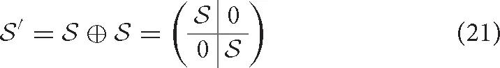
We define duplication as the attachment of a copy of the original molecule in series with the molecule itself. Clearly, relations between the contacts within the original molecule or its copy do not change, while all contacts between the original and copied molecule are in series (see Figure 6). In other words,
In biological polymers, the two linked molecules may be connected by a “linker” region, and new contacts between the two molecules, or between either molecule and the linker, may form. Consider the Greek key barrel diagram, shown again in the inset of Figure 7C, and perform the two eliminations indicated in magenta. The result is the beta/gamma crystallin diagram, present in the protein Nitrollin (Figure 7C, picture in Figure 7A). Duplication (plus elimination and addition of a contact) leads to the beta-B1 crystallin diagram shown in Figure 7D (picture in Figure 7B). In fact, evolutionarily, the beta/gamma crystallins emerged from an ancestral single-domain protein [28].
Figure 6
Figure 7
2.2.6. Additional Discussion
Domain swapping is a protein-protein interaction that involves exchange of contacts between proteins, such that contacts disrupted in the original protein chain are reformed with the corresponding portion of the other protein. A simpler representation is to consider each swapped segment as a node, in which case the standard permutation of the second and fourth nodes of two contacts in series leads to two contacts in parallel (Figures 7E,F). Consider such a simplistic representation of beta/gamma crystallin, where each domain consists of two contacting subdomains. Imagine a domain swap between N-terminal domains, a standard permutation between nodes 2 and 6 (Figures 7E,F). Say the molecules are connected in a single molecule pulling experiment, and the C-terminal domain is less mechanically resilient. Then, upon application of a force pulling at the two ends, we would expect unfolding of the second C-terminal domain first, followed by the swapped N-terminal domains, sequentially, followed by the first C-terminal domain. This is exactly the model proposed by Garcia-Manyes et al. in a recent publication [29], based on single molecule force spectroscopy experiments. Biological circuit topology provides a simple illustration of this prediction, also illustrating how our framework may be applied to provide insights relevant to the interpretation of experiment.
It is apparent from Figure 6A that, starting from the crystallin motif, loss of just a single contact can lead to a topologically isolated N-terminal hairpin, i.e., a single contact between beta strands, not bound to the rest of the protein. In fact, detachment of the N-terminal hairpin of gamma-D crystallin is an early event in Monte Carlo unfolding simulations of this protein [30]. Analysis of biological circuit topology may help to identify possible unfolding mechanisms [14] and structural weaknesses that can lead to unfolding and aggregation in biological proteins. The high content of parallel and cross relations in the crystallin motif may be a reason for its high stability in many proteins.
In summary, we believe that our method represents a useful and intuitive approach to circuit diagram generation, providing insights into key properties of biomolecular structures and the relations between them. We plan to extend and improve our approach to allow for more automated bioinformatic analyses. While we apply our approach to biological structures in the Protein Data Bank, we note that it could also be used in conjunction with Molecular dynamics and analysis tools to study dynamic transitions in biomolecules, including transient structure in intrinsically disordered proteins.
The complete code and documentation is available online.
3. Conclusion
In this article, we developed a framework that can be used to describe, compare, and predict the topological properties of a molecule that is subject to specific molecular operations. More specifically, we considered several generic operations, namely permutation, duplication, inversion, addition/insertion, and elimination. We used examples from structural biology to demonstrate how relationships between molecules can be understood in terms of the biological circuit topology framework, and we introduced a simple toolset for drawing, analyzing, and manipulating circuit diagrams of proteins. Altogether, we present a mathematical approach to the analysis of protein and nucleic acid structure and structural changes that may also be applied to other linear polymers. We expect the formalism extended here and future developments to be relevant to the process of engineering and manipulating molecules according to symmetry rules between their constituents, and we believe our methods and insights could help foster interdisciplinary collaboration and learning in mathematics, chemistry, biology, and related disciplines.
Statements
Data availability statement
All datasets generated for this study are included in the article/Supplementary Material.
Author contributions
AM conceived, designed, and supervised the research. OS and AT conducted the theoretical analysis. JW conducted the biomolecular modeling part and wrote the script. OS, AT, JW, and AM discussed the results and the interpretations. All authors contributed to writing of the manuscript and approved the final version.
Acknowledgments
OS thanks V. Satarifard for introducing him into the subject and H. Antila, M. Miettinen, and A. Valleriani for their helpful discussions.
Conflict of interest
The authors declare that the research was conducted in the absence of any commercial or financial relationships that could be construed as a potential conflict of interest.
Supplementary material
The Supplementary Material for this article can be found online at: https://www.frontiersin.org/articles/10.3389/fphy.2020.00005/full#supplementary-material
References
1.
MizuguchiKGoN. Seeking significance in three-dimensional protein structure comparisons. Curr Opin Struct Biol. (1995) 5:377–82. 10.1016/0959-440x(95)80100-6
2.
BrownID. Topology and chemistry. Struct Chem. (2002) 13:339–55. 10.1023/A:1015872125545
3.
FlapanE. When Topology Meets Chemistry: A Topological Look at Molecular Chirality. Cambridge, UK: Cambridge University Press (2000).
4.
AymeJFBevesJELeighDAMcBurneyRTRissanenKSchultzD. A synthetic molecular pentafoil knot. Nat Chem. (2011) 11:15–20. 10.1038/nchem.1193
5.
BlankenshipJWDawsonPE. Threading a peptide through a peptide: protein loops, rotaxanes, and knots. Protein Sci. (2007) 16:1249–56. 10.1110/ps.062673207
6.
CoskunABanaszakMAstumianRDStoddartJFGrzybowskiBA. Great expectations: can artificial molecular machines deliver on their promise?Chem Soc Rev. (2012) 41:19–30. 10.1039/C1CS15262A
7.
KamienRD. Topology from the bottom up. Science. (2003) 299:1671–3. 10.1126/science.1082510
8.
SiegelJS. Chemical topology and interlocking molecules. Science. (2004) 304:1256–8. 10.1126/science.1099216
9.
BailorMHSunXAl-HashimiHM. Topology links RNA secondary structure with global conformation, dynamics, and adaptation. Science. (2010) 327:202–6. 10.1126/science.1181085
10.
CavalliGMisteliT. Functional implications of genome topology. Nat Struct Mol Biol. (2013) 20:290–9. 10.1038/nsmb.2474
11.
CangZWeiGW. TopologyNet: topology based deep convolutional and multi-task neural networks for biomolecular property predictions. PLoS Comput Biol. (2017) 13:e1005690. 10.1371/journal.pcbi.1005690
12.
CangZMuLWeiGW. Representability of algebraic topology for biomolecules in machine learning based scoring and virtual screening. PLoS Comput Biol. (2017) 14:e1005929. 10.1371/journal.pcbi.1005929
13.
MashaghiAvan WijkRJTansSJ. Circuit topology of proteins and nucleic acids. Structure. (2014) 22:1227–37. 10.1016/j.str.2014.06.015
14.
MuglerATansSJMashaghiA. Circuit topology of self-interacting chains: implications for folding and unfolding dynamics. Phys Chem Chem Phys. (2014) 16:22537–44. 10.1039/C4CP03402C
15.
VerovšekSKMashaghiA. Extended topological persistence and contact arrangements in folded linear molecules. Front Appl Math Stat. (2016) 2:6. 10.3389/fams.2016.00006
16.
NikoofardNMashaghiA. Topology sorting and characterization of folded polymers using nano-pores. Nanoscale. (2016) 8:4643–9. 10.1039/C5NR08828C
17.
HeidariMSatarifardVTansSJEjtehadiMRMashaghiSMashaghiA. Topology of internally constrained polymer chains. Phys Chem Chem Phys. (2017) 19:18389–93. 10.1039/C7CP02145C
18.
SatarifardVHeidariMMashaghiSTansSJEjtehadiMRMashaghiA. Topology of polymer chains under nanoscale confinement. Nanoscale. (2017) 9:12170–7. 10.1039/C7NR04220E
19.
MashaghiARamezanpourA. Circuit topology of linear polymers: a statistical mechanical treatment. RSC Adv. (2015) 5:51682–9. 10.1039/C5RA08106H
20.
MashaghiARamezanpourA. Distance measures and evolution of polymer chains in their topological space. Soft Matter. (2015) 11:6576–85. 10.1039/C5SM01482D
21.
BacharOFischerDNussinovRWolfsonH. A computer vision based technique for 3-D sequence-independent structural comparison of proteins. Protein Eng Design Select. (1993) 6:279–87. 10.1093/protein/6.3.279
22.
PrlićABournePEBlivenSE. Detection of circular permutations within protein structures using CE-CP. Bioinformatics. (2014) 31:1316–8. 10.1093/bioinformatics/btu823
23.
WangLWuLYWangYZhangXSChenL. SANA: an algorithm for sequential and non-sequential protein structure alignment. Amino Acids. (2010) 39:417–25. 10.1007/s00726-009-0457-y
24.
BrandenCToozeJ. Introduction to Protein Structure. 2nd Edn. New York, NY: Garland Science (1999).
25.
HubbardTJMurzinAGBrennerSEChothiaC. SCOP: a structural classification of proteins database. Nucleic Acids Res. (1997) 25:236–9.
26.
GrishinNV. Fold change in evolution of protein structures. J Struct Biol. (2001) 134:167–85. 10.1006/jsbi.2001.4335
27.
BlivenSPrlićA. Circular permutation in proteins. PLoS Comput Biol. (2012) 8:e1002445. 10.1371/journal.pcbi.1002445
28.
KappéGPurkissAGvan GenesenSTSlingsbyCLubsenNH. Explosive expansion of betagamma-crystallin genes in the ancestral vertebrate. J Mol Evol. (2010) 71:219–30. 10.1007/s00239-010-9379-2
29.
Garcia-ManyesSGigantiDBadillaCLLezamizAPerales-CalvoJBeedleAEMet al. Single-molecule force spectroscopy predicts a misfolded, domain-swapped conformation in human YD-crystallin protein. J Biol Chem. (2016) 291:4226–35. 10.1074/jbc.M115.673871
30.
SerebryanyEWoodardJCAdkarBVShababMKingJAShakhnovichEI. An internal disulfide locks a misfolded aggregation-prone intermediate in cataract-linked mutants of human YD-crystallin. J Biol Chem. (2016) 291:19172–83. 10.1074/jbc.M116.735977
Summary
Keywords
topology, matrix representation, protein folding, protein engineering, permutation, duplication, elimination
Citation
Schullian O, Woodard J, Tirandaz A and Mashaghi A (2020) A Circuit Topology Approach to Categorizing Changes in Biomolecular Structure. Front. Phys. 8:5. doi: 10.3389/fphy.2020.00005
Received
02 April 2019
Accepted
06 January 2020
Published
30 January 2020
Volume
8 - 2020
Edited by
Sabre Kais, Purdue University, United States
Reviewed by
Kelin Xia, Nanyang Technological University, Singapore; Ross Douglas Hoehn, Qatar Environment and Energy Research Institute, Qatar
Updates
Copyright
© 2020 Schullian, Woodard, Tirandaz and Mashaghi.
This is an open-access article distributed under the terms of the Creative Commons Attribution License (CC BY). The use, distribution or reproduction in other forums is permitted, provided the original author(s) and the copyright owner(s) are credited and that the original publication in this journal is cited, in accordance with accepted academic practice. No use, distribution or reproduction is permitted which does not comply with these terms.
*Correspondence: Alireza Mashaghi a.mashaghi.tabari@lacdr.leidenuniv.nl
This article was submitted to Physical Chemistry and Chemical Physics, a section of the journal Frontiers in Physics
†These authors have contributed equally to this work
Disclaimer
All claims expressed in this article are solely those of the authors and do not necessarily represent those of their affiliated organizations, or those of the publisher, the editors and the reviewers. Any product that may be evaluated in this article or claim that may be made by its manufacturer is not guaranteed or endorsed by the publisher.