 Giulia Becatti
 Daniela Pedrini
 Bhargav Kasoji
 Fabrizio Paganucci
 Mariano Andrenucci2
- 1Department of Civil and Industrial Engineering, University of Pisa, Pisa, Italy
- 2Electric Propulsion Division, SITAEL S.p.A., Pisa, Italy
Lanthanum hexaboride hollow cathodes represent a viable option for high power Hall effect thruster applications, under development for the next generation of manned and robotic interplanetary missions. In this scenario, SITAEL and the University of Pisa are actively developing high current hollow cathodes capable of providing discharge current in the range 10–100 A to be coupled with high power Hall effect thrusters. The cathode design is based on an in-house theoretical model of the internal sections of the cathode, recently integrated with a simplified model of the cathode plume. Despite the application of hollow cathodes on flight and laboratory model Hall effect thrusters, many questions remain unsolved. In particular, issues related to onset of instabilities, due to plume mode or ion acoustic turbulence, are still unclear, while it is known that they can affect the overall performance of the cathode and thruster unit. This paper focuses on the experimental investigation of the cathode plume by means of measurements of the main plasma parameters, at different operating conditions and for different cathode geometry. Two cathodes were investigated, namely HC20 and HC60, designed to be coupled with SITAEL's HT5k and HT20k (5 kW- and 20 kW-class) Hall effect thrusters. The cathodes were mounted in stand-alone configuration with an auxiliary cylindrical anode. The experimental campaign was performed using triple Langmuir probes as plasma diagnostic system. The probes were mounted on scanning mechanisms to measure the plume parameters at various radial and axial distances from the keeper exit. General trends of electron temperature, plasma potential and plasma density are reported in terms of discharge current, mass flow rate and cathode orifice geometry. The results highlight that the cathode plate orifice selection affects the plume mode onset, giving the possibility to extend the stable mode of cathode operation in the current range required by the thruster.
Introduction
High power space electric propulsion has increased its attractive perspective for the next generation exploration missions and for transportation of large space tugs toward future space stations [1]. These mission scenarios require high power, long life propulsion systems. In this context, high-power Hall effect thrusters are under development in many agencies and industries [2, 3], with the main requirement of a total lifetime of the components in the order of 104 hours.
One of the most critical components of Hall thrusters is the cathode, used to emit the electrons to sustain the discharge and for the neutralization of the beam. Traditionally, hollow cathodes have been the prime choice for these types of thrusters, due to their higher reliability with respect to other types of cathodes [4].
The validation and demonstration of the hollow cathode technology for such long lifetime require the understanding of the main limiting factors impacting the lifetime of the cathodes. Previous works indicated the emitter evaporation [5, 6] and the keeper erosion [7] as the main life-limiting mechanisms.
Although an accurate and conservative description of emitter material consumption has been accepted in most of hollow cathode models, a consistent theoretical solution for the keeper wear process is not available yet.
It is widely accepted that the erosion of the keeper occurs as a result of surface sputtering by ion bombardment. The sputtering yield as a function of xenon ion energy has been measured for the most common keeper materials. For instance, Doerner et al. [8], measured the sputtering yield for molybdenum, tantalum and graphite at ion energy as low as 10 eV.
The prevalence of the keeper erosion clearly emerged after the two major life tests performed by NASA on a 30 cm ion engine, namely the Life Demonstration Test [9] and the Extended-Life Test [10]. At the end of both tests the keeper electrode was completely eroded, exposing the cathode orifice plate to the external discharge plasma. These results have been attributed to high-energy ions bombarding and sputtering the external surfaces of the cathode.
Several different mechanisms have been proposed to identify the source of these energetic ions, including potential hills [11], charge exchange between ions and neutrals [12], double and triple ionization [13, 14], energetic ion production by plasma oscillations largely associated with ionization instabilities [15, 16], and/or by ion acoustic turbulence [17–19].
It is well known that hollow cathodes of this type are characterized by two modes of operation, namely spot and plume mode as first identified in the late 1960s by Rawlin and Pawlik [20]. Spot mode indicates the stable mode of operation desired during the nominal coupling with the thruster, whereas plume mode indicates an unstable mode, characterized by the presence of large-amplitude oscillations in the discharge and keeper voltages, which promote the keeper wear [7, 21–23]. As mentioned above, another phenomenon thought to enhance the keeper wear even when the cathode is in spot mode is the production of high-energy ions, the existence of which was confirmed by direct measurements [18, 19]. The transition between spot and plume mode in general arises when the ratio of discharge current to mass flow rate exceeds a value dependent on various parameters, including the cathode geometry. The onset of plume mode has been associated with ionization instabilities, as reported experimentally by Goebel et al. [24], and recently with the aid of 2D simulations by Mikellides et al. [25]. It has also been proposed that the plume mode is driven by the onset of ion acoustic turbulence [26], which was theoretically predicted to exist in the cathode plume by Mikellides et al. [27, 28], and later verified experimentally by Jorns et al. [18]. In this scenario, experimental analyses are still required to understand the occurrence of the transition between plume and spot mode and how it is affected by the cathode parameters.
Although a remarkable effort has been expended on numerical simulations and theoretical studies, extensive experimental activities are still needed to characterize the plume plasma parameters and evaluate the cathode life. For these reasons, we carried out experimental campaigns to increase our knowledge of the main cathode life-limiting factors. The paper presents the characterization of the background plume plasma parameters and electrical current-voltage curves of two hollow cathodes, analyzing their main mode of operation. Tests were carried out on two hollow cathodes at various operating conditions and geometries. In particular, the effect of different cathode plate orifice geometries on the plasma parameters and plume mode onset is examined.
The items under test, named HC60 and HC20, are hollow cathodes conceived for high power Hall thrusters under development at SITAEL. HC60 is capable of providing discharge current between 15 and 90 A, whereas HC20 was designed to sustain 5 to 30 A. According to the available experimental setup, the maximum current delivered by the laboratory power supplies was 50 A. As such, HC60 was tested in an operating envelope smaller than its design range, varying the discharge current between 10 and 50 A. Further experimental campaigns are in progress to extend the capability of the setup to reach higher current levels.
The test campaign of each cathodes was performed in a vacuum facility available at SITAEL. The measurements in the plume region of the cathodes were performed with triple Langmuir probes, which offer the possibility to directly measure the plasma parameters as electron temperature, plasma density and potential without the application of any voltage sweep on the probe.
This paper is organized as following: the cathodes are described in section Cathodes Description, the experimental setup and the method adopted to analyze the results are outlined in section Experimental Setup. Next, the cathodes electrical performance is presented in section Hollow Cathodes Performance, and finally the plasma parameters measured in the cathodes plume are described in section Plume Characterization.
Cathodes Description
The general architecture of the cathodes is shown in Figure 1. The thermionic emission material is shaped as a hollow cylinder (emitter) and located inside a tube. The tube, made of a refractory metal, terminates with an orifice. The emitter is held in position against the orifice plate by means of a spacer pushed by a spring. The propellant is injected inside the tube at a given mass flow rate, and a proper selection of the orifice diameter establishes the pressure conditions inside the cathode to facilitate the ionization process. The cathodes are normally tested with xenon, although the operation with alternative propellants is considered possible, as demonstrated with krypton [29]. The cathode is enclosed by the keeper, an electrode used to provide the discharge ignition by applying a positive potential with respect to the inner tube. Another important function of the keeper is to protect the internal parts of the cathode from ion bombardment.
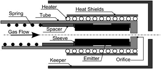
Figure 1. Hollow cathode general architecture.
HC60 was designed to be coupled with SITAEL's HT20k, a high-power Hall effect thruster under development for space exploration and transportation [30]. The nominal current range required by the thruster is 30–60 A. The HC60 guarantees stable operation between 15 and 100 A at a mass flow rate lower than 3 mg/s (Xe). HC20 is the hollow cathode developed for SITAEL's HT5k, a mid-range power Hall effect thruster which requires 5–20 A of discharge current [31]. HC20 can reliably provide 5–30 A at a mass flow rate lower than 2.5 mg/s (Xe). Both cathodes were previously tested in stand-alone configuration to characterize their performance as well as in coupled mode with the thrusters [32].
The design of both cathodes follows the general architecture shown in Figure 1. Due to the different current levels required from HC60 and HC20, the main differences between the two cathodes lie in the emitter and orifice dimensions. Approximately, the emitter of HC60 has a 35% larger diameter and a 40% longer length with respect to HC20. Considering the different emitter geometry, the rest of the cathode dimensions are increased accordingly. The HC60 cathode plate orifice diameter is 60% larger as compared with HC20 (nominal geometries).
HC60 is assembled with a dedicated heater, used to heat up the cathode prior to ignition. The heater is turned on for 10 min at 300 W of power so that the emitter temperature is increased to allow for the thermionic emission. In this way, after the initialization of the mass flow rate, the ignition can be performed by applying only the discharge voltage between the cathode and the keeper required to ionize the propellant.
HC20 is manufactured without a dedicated heater. The ignition procedure of HC20 thus requires the initialization of the propellant flow rate, usually higher (up to three times) with respect to a cathode provided with a heater, and then the application of a high voltage (800–1,000 V) between keeper and cathode to initiate the gas breakdown.
The emitter material selected for these high current cathodes is lanthanum hexaboride (LaB6), which provides electrons through the field-enhanced thermionic effect. LaB6 is characterized by a work function of 2.67 eV [33], and, consequently, the operating temperature of the LaB6 emitter to provide a current density in the order of 105 A/m2 is about 1,700°C. Despite the high operating temperature of the boride compound, LaB6 was selected for its low evaporation rate and low sensitivity to contaminants and air exposure.
The main functional dimensions of the cathode derive from a theoretical model developed at SITAEL [34] to describe the operation of orificed hollow cathodes. The model results were analyzed to select the emitter inner and outer diameters, the emitter length, and the orifice diameter and length. The plasma model is then coupled with a dedicated lumped-parameter thermal model, and the combined systems of equations are solved by means of an iterative procedure to compute the plasma parameters, temperature profile, and total discharge power. For a detailed description of the model see Albertoni et al. [35] and Pedrini et al. [36, 37].
Both HC60 and HC20 are tested with different orifice dimensions, defined by the orifice aspect ratio (AR), which is the ratio of orifice length to orifice diameter. To assess the effect of only the diameter, the length of the orifice is maintained constant for both cathodes. Thus, larger AR corresponds to smaller orifice diameter, while smaller AR corresponds to larger diameter.
Experimental Setup
The experimental campaign was performed in SITAEL's LFF vacuum facility.
The experimental apparatus includes a cylindrical anode made of stainless steel and the cathode under test, both placed over a base plate, insulated with appropriate ceramic supports. The cylindrical anode allows the current to attach radially and the neutral gas to flow unimpeded downstream [5]. The anode has an inner diameter of 150 mm, a length of 200 mm and is placed at a distance of 30 mm from the keeper exit plane. The experimental setup in shown in Figure 2 (left) with HC20 and in Figure 2 (right) with HC60.
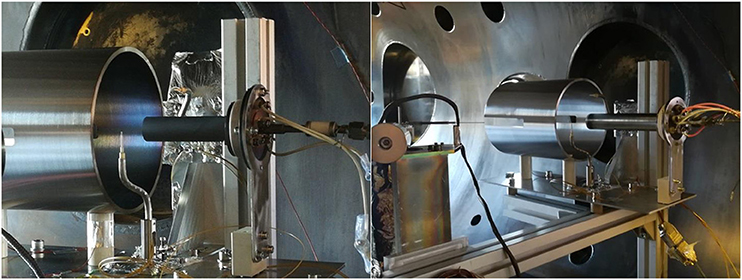
Figure 2. HC20 (Left) and HC60 (Right) mounted on the test setup.
Langmuir Probes
As mentioned above, the analysis of the cathode plume parameters was carried out with triple Langmuir probes placed on dedicated motors capable of scanning the plume along three different directions. The application of triple Langmuir probes offers interesting features to study the plume of hollow cathodes. As a matter of fact [38], triple Langmuir probes do not require any voltage sweep, and they guarantee the continuous acquisition of the parameters, along the whole scanning path.
Fast Probe
The electron temperature, plasma potential and plasma density along the axis of the cathode were measured using a triple Langmuir probe mounted on an articulated arm. The moving system and the arm were the same used to measure the plasma parameters inside the SITAEL Hall thruster channel [39], whereas the Langmuir probe was modified according to the expected plasma parameters in the cathode plume. Following the approach described in Andreussi et al. [39], the arm rapidly inserts and extracts the probe from the cathode plume, with a maximum residence time in the dense plasma region of less than 0.2 s. It is important to notice that, even though the residence time of the probe is less than 0.2 s, such measurements are intrusive, since the spatial gradients as well as part of the plasma dynamics may be affected by the probes [40]. As a matter of fact, all the fundamental plasma frequencies are higher than few Hz, and the plasma rapidly adapts itself to the presence of the probe. The measurements thus refer to the plasma conditions with the presence of the probe, which differ from the unperturbed conditions. A careful examination of the variation in cathode-anode discharge voltage and the cathode-reference-potential during the probe insertion gives a rough estimation of the plasma perturbation induced by the probe. Additional considerations regarding the variations in measured voltage are proposed in section Plume Characterization.
The three electrodes of the probe are made of a 0.25 mm dia. tungsten wire (99.9% purity) and are placed inside a 1.7 mm dia. alumina tube. The electrodes are 3 mm long and are separated by a distance of 0.5 mm. The probe remains in a parking position when not in use, to reduce the interference with the plasma plume and possible deterioration of the probe itself. A high-speed magnetic actuator allows for the fast insertion of the probe inside the plasma. An encoder is used to measure the probe position during the insertion. The movement system was designed to ensure a quasi-linear trajectory of the probe tip across the channel exit. Figure 3 shows the trajectory of the fast probe (left figure, in red). The probe tip stops at 0.9 mm before the keeper entrance when in use with HC20 and at the keeper entrance when in use with HC60. The quasi-linear trajectory is ensured at a distance up to 100 mm away from the cathode, with a maximum radial error of 1 mm.

Figure 3. Concept of the triple Langmuir probes scanning path.
Horizontal and Vertical Probes
The plasma parameters were measured at a fixed radial distance with respect to the keeper exit with two additional triple Langmuir probes. The Langmuir probes were mounted on dedicated motors, able to scan the cathode plume horizontally and vertically.
A LabVIEW-based software controlled the motors movement. The acquisition was performed at fixed points along the scanning circumference. The probes remain in parking position (at 90° with respect to the cathode centerline) when not in use. The dimensions of the electrodes and the ceramic insulator are the same as for the fast probe. The scanning trajectory performed by the horizontal and vertical probes is shown in Figure 3 (in blue).
The probes scan horizontally and vertically the cathode plume at a radial distance of 61.5 mm from the keeper exit.
Langmuir Probes Analysis
The analysis of the measurements collected by the triple Langmuir probes was performed with standard techniques, as described in Chen and Sekiguchi [38]. The plasma conditions in the cathode plume allowed for applying the thin sheath theory along the whole scanning positions. The three electrodes were connected in “voltage mode” (see Figure 4), in which one of them (namely, electrode F) is left floating, while the bias voltage is applied between electrode C and electrode B.
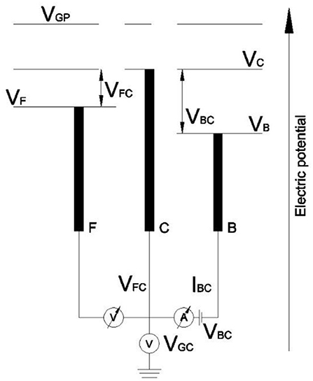
Figure 4. Triple Langmuir probe electrodes configuration.
In the “voltage mode” configuration, the floating voltage (VFC) and the current passing through electrode C and electrode B (I) are measured. Hence, the electron temperature (Te), plasma density (ne) and plasma potential with respect to electrode C (VGP) are obtained by solving the following system of equations:
The applied bias voltage was set to 0 and 36 V, and multiple probe acquisitions were performed with different electrode arrangements, to compensate the geometrical differences of the electrodes.
After a preliminary evaluation of the model results, the thin sheath theory resulted applicable everywhere. The data will be further analyzed implementing the parameterization described in Mausbach [41] of the Laframboise solution for cylindrical Langmuir probes. In addition, a Bayesian integrated data analysis will be implemented, following the approach of Andreussi et al. [39].
Vacuum Facility and Electrical Test Equipment
The test setup was accommodated in SITAEL's LFF vacuum facility [29]. LFF consists of two stainless steel AISI 316 vessels: the main chamber (MC) and the auxiliary chamber (AC). The main chamber has a diameter of 1.2 m and a length of 2.8 m, whereas the auxiliary chamber is 0.5 m in-diameter, 1 m in-length. The two volumes are connected by a large gate valve (LGV) which can be exploited to use the auxiliary chamber as recovery area during maintenance and regeneration of the MC. LFF is equipped with two separated pumping systems. The main pumping system (MPS) is located in the MC and includes a rotary pump Varian Triscroll PTS 600 (28 m3/h) for fore vacuum, a turbopump Varian TV-2000HT (2000 l/s) for high vacuum, a cryopump Leybold Coolvac 1500 for ultra-high vacuum, and a cold head Leybold Coolpower 140T. The auxiliary pumping system (APS), located in the AC, includes a rotary pump Varian Triscroll PTS 300 (15 m3/h) for fore vacuum and a turbopump Varian V-301HT (300 l/s) for high vacuum. The pressure level in the chamber is continuously monitored by one Alcatel AHC 1010 sensor and one Leybold ITR90 sensor both placed in the AC, and two Leybold ITR90 sensors placed in the MC. The facility can reach an ultimate pressure lower than 5 × 10⁻⁶ Pa.
The electrical equipment to test HC20/HC60 includes: anode-cathode power supply TTi Dual CPX400D 20–60 V/Regatron TopCon Quadro 50–200 V; keeper-cathode power supply Magna Power TSD 1000-15 15–1,000 V/Sorensen DLM150-20E 20–150 V; HC60 heater TTi CPX400A 20–60 V. The relative accuracy provided by the power supplies readings is within ±2%.
The diagnostic system includes 5 K-type thermocouples, located in the two anode insulation supports, the horizontal and vertical probes motors and the base plate. All the measurements are recorded via LabVIEW DAQ. The cathode was fed with N48 grade of xenon. The propellant flow rate is controlled by one Bronkhorst F-201C-FAC-22-V.
Hollow Cathodes Performance
The HC20 and HC60 were tested in their operating envelopes, namely 10–30 A discharge current, 1–2 mg/s xenon mass flow rate for HC20; 10–50 A discharge current, 1–2.5 mg/s xenon mass flow rate for HC60. Furthermore, both cathodes were subjected to geometrical changes, namely the performance differences were assessed with two different orifice length-to-diameter aspect ratios. The tests were carried out with the keeper always in floating conditions, with a background pressure lower than 8 × 10⁻³ Pa.
The I-V characteristic curves of the cathodes are shown in Figure 5. The curves report the discharge voltage, keeper voltage and cathode-reference potential (CRP, namely the potential difference between cathode and ground) vs. the discharge current for the various conditions tested.
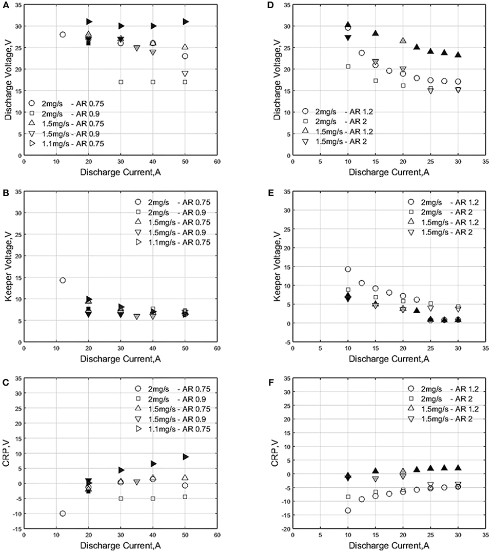
Figure 5. Voltage parameters as function of the discharge current: (A) HC60 discharge voltage, (B) HC60 keeper voltage, (C) HC60 CRP, (D) HC20 discharge voltage, (E) HC20 keeper voltage, (F) HC20 CRP. Black markers refer to plume mode, white markers to spot mode, gray markers to transition.
The discharge voltage and keeper voltage indicate power supplies readings, whereas the CRP was measured with a digital multimeter.
The trends in the I–V characteristics are similar to previous characterization tests performed on the same cathodes [29]. Nevertheless, comparing the I-V curves reported in Pedrini et al. [29] with the ones presented in this paper, a slight improvement of the cathode performance is observed, in terms of operating envelope ensuring cathode running in spot mode. This occurrence is ascribed to the replacement of the anode plate of the previous setup with a cylindrical anode. As a matter of fact, the new anode configuration allows the cathodes to sustain the discharge at lower mass flow rate, at a given current, with the keeper left floating.
Figures 5A,D present the electrical characteristics in terms of discharge voltage as a function of discharge current for the two cathodes at the various operating conditions and ARs. The discharge voltage varies between 16 and 31 V for HC60, between 15 and 30 V for HC20. The general trends presented here are consistent with the behavior of cathodes of this power range found in the literature [16, 42, 43].
The higher discharge voltages observed at lower current levels can generally be ascribed to a higher power required to maintain the emitter temperature due to insufficient plasma bombardment on the emitter surface [4]. However, a deeper understanding of the processes involved in this operational regime would require additional information. As a matter of fact, the sustainment of the emission as the discharge current is reduced involves the coupling of different processes in the cathode interior [44]. First of all, a possible increase of the internal plasma potential due to an increase of the discharge voltage could reduce the power deposition on the emitter surface. This occurrence is due to recombining electrons, to which the power coming from ion bombardment must adapt, having an impact on the plasma density, on the ionization and hence on the neutral gas. As such, the explanation of the trend in the discharge voltage should be supported by complete 2D plasma simulations, or by simplified analyses based on internal plasma measurements, which will be considered among the future developments of the described activities.
Decreasing the mass flow rate implies a decrease in plasma density leading to an increase of the cathode discharge voltage if the same current level is maintained [4], as experimentally evidenced in the available literature [43, 45, 46]. Similar trends observed for the keeper voltage are reported in Goebel and Chu [47].
The effect of orifice geometry changes is similar to the variation of the mass flow rate. Increasing the orifice diameter (thus lowering the AR, for the same orifice length) causes higher discharge voltage, at given operating conditions. This effect can be theoretically explained considering that a larger orifice leads to a lower input power due to the resistive drop in the plasma across the orifice [48]. The resistive drop, derived from Ohm's law, affects the plasma potential in the orifice region, which in turn determines the voltage drop at the orifice sheath, ultimately defining the corresponding power deposition. As such, the maintenance of the emitter operative temperature requires higher input power from the emission region, obtained with a higher voltage drop in the emitter sheath, in turn increasing the total discharge voltage. The cathode model described in [34] corroborates this explanation; however, one of the main assumption of the model is the perfect contact conditions among surfaces (thermal gluing), an ideal situation from which experiments deviate by an amount difficult to be quantified. Further analyses will be performed, including the evaluation of the possible presence of ion acoustic turbulence at the keeper exit, which may be the cause of the increase in the discharge voltage as well [18, 49].
For the whole operative conditions tested, the keeper was used only for the ignition of the cathode and then left floating. The keeper voltage, shown in Figure 5B for HC60 and Figure 5E for HC20, follows similar found in the literature [43], decreasing as the discharge current increases, without significant variation with the propellant flow rate or the orifice geometry.
The CRP, being the potential difference between cathode and ground, mainly depends both on the characteristics of the cathode plume (especially in terms of its divergence) and on the test setup. Despite the latter dependence on the test setup, the experimental campaigns are useful for a comparison between different cathode geometries and operating conditions, as well as to verify the operational capability of the cathodes. Nevertheless, the coupling tests with the respective Hall thrusters are essential to address the effect of the cathode on the thruster unit performance and lifetime. The CRP values as a function of discharge current and mass flow rates follow similar trends as those reported in Thomas et al. [46]. From Figures 5C,F it can be noticed that the CRP increases for both cathodes with the following conditions: increase in discharge current, decrease in mass flow rate, and decrease in orifice diameter. From visual observation, the conditions listed here above correspond to a wider and denser plume, which likely interferes with the experimental setup mounted on the vacuum chamber. Moreover, the positive CRP readings at some conditions (namely for HC20 at 1.5 mg/s with larger orifice, for HC60 at 1.1 and 1.5 mg/s with larger orifice) correspond to the transition to plume mode [46].
Plume Characterization
Plasma parameters were measured by means of the Langmuir probes described in section Langmuir Probes.
Figure 6 shows the plume parameters measured with the fast probe at the scanning position closest to the cathode, immediately before the keeper entrance. The graphs show a comparison between the different operating conditions and provide trends of the parameters varying the discharge current. The parameters considered are plasma density (a), electron temperature (b), plasma potential with respect to ground (c) for HC20 and plasma density (d), electron temperature (e) and plasma potential with respect to ground (f) for HC60.
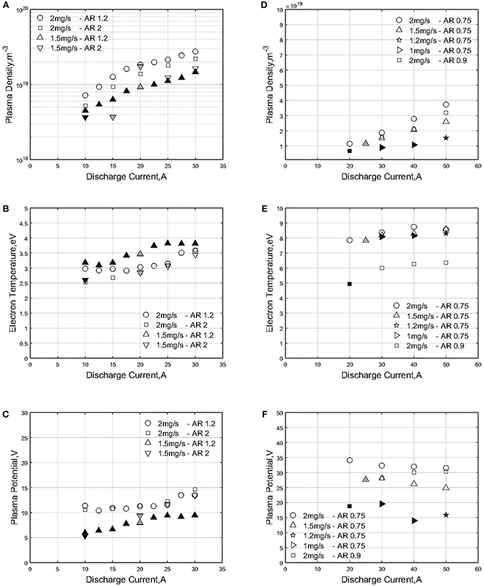
Figure 6. Plume plasma parameters measured at the exit of the keeper as function of the discharge current: (A) HC20 plasma density, (B) HC20 electron temperature, (C) HC20 plasma potential with respect to ground, (D) HC60 plasma density, (E) HC60 electron temperature, (F) HC60 plasma potential with respect to ground. Black markers refer to plume mode, white markers to spot mode, gray markers to transition.
The plasma parameters presented were calculated with the thin sheath theory described in section Experimental Setup. The relative accuracy is ± 30% for the electron temperature and plasma potential, and ± 50% for the plasma density. The error, in line with the error associated with these types of diagnostics as found in the literature [50], is computed with standard propagation analysis [51], considering the data acquisition error (current and voltage read by the DAQ system) and the position of the probe accuracy. Furthermore, the perturbation induced by the probe insertion on the CRP measurements is taken into account. No significant changes of the CRP were observed until the probe tip reached the proximity of the keeper, where a change of ~10% of the CRP was measured.
Figures 6A,D show plasma density for HC20 and HC60 as a function of operating conditions and orifice geometries. The plasma density follows similar trends as found in the literature [18, 46, 52], increasing when the discharge current is increased, and decreasing when the mass flow rate is decreased. Interestingly, with a larger orifice and for the same operating conditions, the plasma density at the exit of the keeper increases for both HC20 and HC60. Additional studies are in progress to understand the effect of the anomalous diffusion in hollow cathodes due to geometrical changes.
Electron temperature, shown in Figures 6B,E for HC20 and HC60, seems not particularly affected by the variations of operative conditions, considering measurement accuracy. Electron temperature increases of about 30% when the discharge current is increased, while it decreases about 10% at higher mass flow rate. In addition, a larger orifice entails an increase of the electron temperature. Possible explanations to this effect are hereafter proposed. First, a larger orifice leads to lower neutral density in the plume, due to the larger expansion, and thus the loss of electron energy due to collision with neutrals tends to decrease. Secondly, increasing the orifice diameter could increase the instabilities in the plume which in turn enhance the electron heating.
Figures 6C,F show the plasma potential with respect to ground measured in HC20 and HC60. The potential at the exit of HC60 is maintained between 23 and 30 V, except for the case at 20 A, 2 mg/s, AR 0.9, where it is at 15 V. The potential at the exit of HC20 sets in the range 5–15 V. The difference between the two cathodes potential operating at the same discharge current could be attributed to the different position at which the measurements are made (immediately outside the keeper for HC60, at a distance of 0.9 mm for HC20) and to the different size, which affects the overall plasma resistivity [4].
Cathode Modes of Operation
In general, hollow cathodes for electric thrusters are characterized by two modes of operation [4]. Spot mode of operations, characterized by a small, convergent plume (Figure 7, left), is desirable when the cathode is coupled with the thruster, due to the low amplitude oscillations. Plume mode of operation arises at low mass flow rates or at the extreme range of the discharge current interval. Plume mode is characterized by relatively large amplitude oscillations of discharge voltage and discharge current. The onset of plume mode is associated with a divergent plume, as shown in Figure 7 (right).
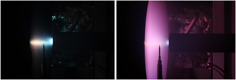
Figure 7. HC20 cathode modes of operation: spot mode (Left) and plume mode (Right).
The measurement of the plasma parameters at the selected operating conditions allowed for characterizing the plasma in the different modes of operation of the cathodes. The transition between plume and spot mode was visually detected and then associated with oscillations of the cathode reference potential, whose amplitude reached roughly 30% of the voltage value in plume mode, compared to about 1.5% in spot mode. The graphs illustrated in Figures 5, 6 present the plasma parameters for spot (white markers) and plume (black markers) modes. Both cathodes experience plume mode when certain conditions are reached. In particular, HC20 operates in plume mode at 1.5 mg/s of mass flow rate for the whole range of discharge current with the smaller AR orifice, whereas it operates in plume mode only at 10 A when tested with the larger AR ratio, at the same mass flow rate. The plasma parameters for HC20 (Figure 6, right column) show that plume mode of operation is characterized by a 30% higher electron temperature and 40% lower plasma potential.
Conclusion
Hollow cathodes for Hall effect thrusters are required to provide the electron current needed to sustain the discharge and to neutralize the exit ion beam. The high-power Hall effect thrusters under development at SITAEL and in many agencies and industries necessitate hollow cathodes capable of emitting relatively high currents (tens of amperes) with the minimum power consumption and for the life dictated by the mission scenarios.
The hollow cathodes subjected to this research, named HC20 and HC60, have been developed at SITAEL to be coupled with a 5 kW and a 20 kW Hall effect thruster. So far, the cathode performance was investigated at SITAEL by measuring I-V characteristics at different operating conditions. In this paper, a wider investigation has been presented, having integrated I-V measurements with plasma parameter measurements in the plume, performed for different cathode geometries. The diagnostics, based on triple Langmuir probes, have demonstrated to be effective and reliable.
The measured plasma parameters have shown typical ranges of values as found in the literature, along with expected trends as a function of operating conditions and cathode geometry. In particular, a smaller cathode plate orifice diameter was found to shift the transition to plume mode at lower discharge current and mass flow rate. This trend, if confirmed by further tests, could give indications for the design of more efficient cathodes with a longer lifetime.
Further studies are in progress to complete the characterization of HC60 at different orifice aspect ratios and to further evaluate the characteristics of plume mode in terms of plasma parameters and voltage oscillations.
Author Contributions
The experimental campaign and the data analysis were performed by GB and BK with the supervision of FP. The cathode design was conceived by DP with the supervision of FP and MA. All the authors contributed to the writing of the paper.
Conflict of Interest Statement
The authors declare that the research was conducted in the absence of any commercial or financial relationships that could be construed as a potential conflict of interest.
Acknowledgments
The authors would like to thank Nicola Giusti and Stefano Caneschi, Luca Pieri, Carlo Tellini, and Ugo Cesari for the preparation of the experimental setup and the electronic assistant in the diagnostic measurements. Fruitful discussion with Tommaso Andreussi and Federico Torrini has been helpful in the application of plasma diagnostics technology. This work was performed at SITAEL S.p.A., in collaboration with University of Pisa.
References
1. Del Amo JG. Electric propulsion activities at ESA. In: 35th International Electric Propulsion Conference. Atlanta, GA (2017).
3. Boniface C, Arcis N. An overview of electric propulsion activities at CNES. In: 35th International Electric Propulsion Conference. Atlanta, GA (2017).
4. Goebel DM, Katz I. Fundamentals of Electric Propulsion: Ion and Hall Thrusters. Vol. 1. John Wiley & Sons (2008).
5. VanNoord JL, Kamhawi H, McEwen HK. Characterization of a High Current, Long Life Hollow Cathode. NASA Technical Report (2006).
6. Becatti G, Goebel DM, Polk JE, Guerrero P. Life evaluation of a lanthanum hexaboride hollow cathode for high-power hall thruster. J Propul Power. (2018) 4:893–900. doi: 10.2514/1.B36659
7. Sengupta A, Brophy J, Anderson J, Garner C, Banks B, Groh K. An overview of the results from the 30,000 Hr life test of deep space 1 flight spare ion engine. In: 40th AIAA/ASME/SAE/ASEE Joint Propulsion Conference and Exhibit, Joint Propulsion Conferences. Fort Lauderdale,FL (2004).
8. Doerner RP, Whyte DG, Goebel DM. Sputtering yield measurements during low energy xenon plasma bombardment. J Appl Phys. (2003) 93:5816–23. doi: 10.1063/1.1566474
9. Polk J, Anderson J, Brophy J, Rawlin V, Patterson M, Sovey J, et al. An overview of the results from an 8200 hour wear test of the NSTAR ion thruster. In 35th Joint Propulsion Conference and Exhibit. Los Angeles, CA (1999).
10. Sengupta A, Brophy J, Goodfellow K. Status of the extended life test of the deep space 1 flight spare ion engine after 30,000 hours of operation. In 39th AIAA/ASME/SAE/ASEE Joint Propulsion Conference and Exhibit. Huntsville, AL (2003).
11. Kameyama I. Effects of Neutral Density on Energetic Ions Produced Near High-Current Hollow Cathodes. NASA CR-204154. (1997).
12. Katz I, Mikellides I, Goebel D, Jameson K, Wirz R, Johnson L. Production of high energy ions near an ion thruster discharge hollow cathode. In: 42nd AIAA/ASME/SAE/ASEE Joint Propulsion Conference & Exhibit. Sacramento, CA (2006).
13. Gallimore AD, Rovey JL, Herman DA. Erosion processes of the discharge cathode assembly of ring-cusp gridded ion thrusters. J Propul Power. (2007) 23:1271–8. doi: 10.2514/1.27897
14. Williams GJ, Domonkos MT, Chavez JM. Measurement of doubly charged ions in ion thruster plumes. In: 27th International Electric Propulsion Conference. Pasadena, CA. (2001). p. 15–19.
15. Goebel DM, Jameson K, Katz I, Mikellides IG. Energetic ion production and keeper erosion in hollow cathode discharges. In: IEPC Paper. (2005).p. 266.
16. Goebel DM, Watkins RM, Jameson KK. LaB6 hollow cathodes for ion and Hall thrusters. J Propul Power. (2007) 23:552–8. doi: 10.2514/1.25475
17. Mikellides IG, Ira K, Dan MG, Kristina KJ, James EP. Wear mechanisms in electron sources for ion propulsion, II: discharge hollow cathode. J Propul Power. (2008) 24:866–79. doi: 10.2514/1.33462
18. Jorns BA, Mikellides IG, Goebel DM. Ion acoustic turbulence in a 100-A LaB 6 hollow cathode. Phys Rev E. (2014) 90:063106. doi: 10.1103/PhysRevE.90.063106
19. Dodson CA, Perez-Grande D, Jorns BA, Goebel DM, Wirtz RE. Ion heating measurements on the centerline of a high-current hollow cathode plume J Propul Power. (2018) 34:1225–34. doi: 10.2514/1.B36788
20. Rawlin VK, Pawlik EV. A Mercury plasma-bridge neutralizer, J Spacecraft Rockets. (1968) 5:814–20. doi: 10.2514/3.29363
21. Brophy J, Garner C. Tests of high-current cathodes for ion engines. In: 24th AIAA/ASME/SAE/ASEE Joint Propulsion Conference. Boston, MA (1988).
22. Brophy J, Brim D, Polk J, Henry M. The DS1 hyper-extended mission. In: 38th AIAA/ASME/SAE/ASEE Joint Propulsion Conference and Exhibit, Joint Propulsion Conferences. Indianapolis, IN: American Institute of Aeronautics and Astronautics (2002).
23. Goebel DM, Jameson KK, Katz I, Mikellides IG. Potential fluctuations and energetic ion production in hollow cathode discharges. Phys Plasm. (2007) 14:103508. doi: 10.1063/1.2784460
24. Goebel DM, Jameson KK, Katz IJ, Mikellides IG. Plasma potential behavior and plume mode transitions in hollow cathode discharges. In: 30th International Electric Propulsion Conference. Florence (2007).
25. Mikellides IG, Guerrero P, Ortega AL, Polk J. Spot-to-plume mode transition investigations. In: The HERMeS Hollow Cathode Discharge Using Coupled 2-D Axisymmetric Plasma-Thermal Simulations. 2018 Joint Propulsion Conference. Cincinnati, OH (2018).
26. Georgin MP, Jorns B, Alec A, Gallimore D. An experimental and theoretical study of hollow cathode plume mode oscillations. In: 35th International Electric Propulsion Conference, IEPC-2017. Atlanta, GA (2017).
27. Mikellides IG, Katz I, Goebel DM, Polk JE. Hollow cathode theory and experiment. II. a two-dimensional theoretical model of the emitter region. J Appl Phys. (2005) 98:113303–14. doi: 10.1063/1.2135409
28. Mikellides IG, Katz I, Goebel DM, Jameson KK. Evidence of nonclassical plasma transport in hollow cathodes for electric propulsion. J Appl Phys. (2007) 101:15. doi: 10.1063/1.2710763
29. Pedrini D, Torrini F, Grassi J, Paganucci F, Andreussi T, Misuri T, et al. Development of hollow cathodes for 5 to 20 kW hall thrusters. In: 35th International Electric Propulsion Conference. Atlanta, GA (2017).
30. Piragino A, Leporini A, Giannetti V, Pedrini D, Rossodivita A, Andreussi, et al. Characterization of a 20 kW-class hall effect thruster. In: 35th International Electric Propulsion Conference. Atlanta, GA (2017).
31. Giannetti V, Piragino A, Faraji F, Reza M, Leporini A, Saravia M, et al. Development of a 5kW low erosion hall effect thrsuter. In: 35th International Electric Propulsion Conference. Atlanta, GA (2017).
32. Pedrini D, Becatti G, Cannelli F, Tellini C, Torrini F, Ducci, et al. (2018). Overview of Hollow Cathodes Development at Sitael. Seville: Space Propulsion 2018, 14 – 18 May, SP2018_00280.
34. Pedrini D, Albertoni R, Paganucci F, Andrenucci M. Modeling of LaB6 hollow cathode performance and lifetime. Acta Astronautica. (2015) 106:170–8. doi: 10.1016/j.actaastro.2014.10.033
35. Albertoni R, Pedrini D, Paganucci F, Andrenucci M. A reduced-order model for thermionic hollow cathodes. IEEE Trans Plasma Sci. (2013) 41:1731–45. doi: 10.1109/TPS.2013.2266512
36. Pedrini D, Albertoni R, Paganucci F, Andrenucci M. Theoretical model of a lanthanum hexaboride hollow cathode. IEEE Trans Plasma Sci. (2015) 43:209–17. doi: 10.1109/TPS.2014.2367815
37. Pedrini D, Cannelli F, Ducci C, Misuri T, Paganucci F, Andrenucci M. Hollow cathodes development at Sitael. In: Proceedings of the Space Propulsion. Roma (2016).
38. Chen SL, Sekiguchi T. Instantaneous direct-display system of plasma parameters by means of triple probe. J Appl Phys. (1965) 36:2363–75. doi: 10.1063/1.1714492
39. Andreussi T, Giannetti V, Leporini A, Saravia MM, Andrenucci M. Influence of the magnetic field configuration on the plasma flow in Hall thrusters. Plasma Phys Control Fusion. (2017) 60:1. doi: 10.1088/1361-6587/aa8c4d
40. Jorns BA, Goebel DM, Hofer RR. Plasma perturbations in high-speed probing of Hall thruster discharge chambers: quantification and mitigation. In: 51st AIAA/SAE/ASEE Joint Propulsion Conference. Orlando (2015).
41. Mausbach M. Parametrization of the laframboise theory for cylindrical langmuir probe analysis. J Vacuum Sci Technol A. (1997) 15:2923–9. doi: 10.1116/1.580886
42. Kubota K, Oshio Y, Watanabe H, Cho S, Ohkawa Y, Funaki I. Numerical and experimental study on discharge characteristics of high-current hollow cathode. In: 52nd AIAA/SAE/ASEE Joint Propulsion Conference Salt Lake, UT (2016).
43. Chu E, Goebel DM. High-current lanthanum hexaboride hollow cathode for 10-to-50-kW Hall thrusters. IEEE Trans Plasma Sci. (2012) 40:2133–44. doi: 10.1109/TPS.2012.2206832
44. Mikellides IG, Goebel DM, Snyder JS, Katz I, Herman DA. The discharge plasma in ion engine neutralizers: numerical simulations and comparisons with laboratory data. J Appl Phys. (2010) 108:113308. doi: 10.1063/1.3514560
45. Goebel DM, Chu E. High-current lanthanum hexaboride hollow cathode for high-power hall thrusters. J Propul Power. (2014) 30:35–40. doi: 10.2514/1.B34870.
46. Thomas RE, Kamhawi H, Williams Jr GJ. High current hollow cathode plasma plume measurements. In: 33rd International Electric Propulsion Conference. (Washington, DC) (2013).
47. Goebel DM, Chu E. High current lanthanum hexaboride hollow cathodes for high power hall thrusters. In: 32nd International Electric Propulsion Conference.. Wiesbaden (2011).
48. Katz I, Mikellides IG, Goebel DM, Polk DE. Plasma heating of inert gas hollow cathode inserts. In: 30th International Electric Propulsion Conference (2007).
49. Ortega AL, Jorns BA, Mikellides IG. Hollow cathode simulations with a first-principles model of ion-acoustic anomalous resistivity. J Propul Power. Florence (2018) 34:1026–38. doi: 10.2514/1.B36782
50. Goebel DM, Jameson KK, Watkins RM, Katz I, Mikellides IG. Hollow cathode theory and experiment. I plasma characterization using fast miniature scanning probes. J Appl Phys. (2005) 98:113302. doi: 10.1063/1.2135417
51. Coleman HW, Steele WG. Experimentation, Validation, and Uncertainty Analysis for Engineers. John Wiley & Sons. (2009).
Keywords: hollow cathode, electric propulsion (EP), Hall effect thrusters (HET), plasma diagnostic, space exploration
Citation: Becatti G, Pedrini D, Kasoji B, Paganucci F and Andrenucci M (2019) Triple Langmuir Probes Measurements of LaB6 Hollow Cathodes Plume. Front. Phys. 7:27. doi: 10.3389/fphy.2019.00027
Received: 12 November 2018; Accepted: 15 February 2019;
Published: 13 March 2019.
Edited by:
Gianpiero Colonna, Italian National Research Council (CNR), ItalyReviewed by:
Ioannis (Yiangos) G. Mikellides, NASA Jet Propulsion Laboratory (JPL), United StatesJayr Amorim, Instituto Tecnológico de Aeronáutica, Brazil
Copyright © 2019 Becatti, Pedrini, Kasoji, Paganucci and Andrenucci. This is an open-access article distributed under the terms of the Creative Commons Attribution License (CC BY). The use, distribution or reproduction in other forums is permitted, provided the original author(s) and the copyright owner(s) are credited and that the original publication in this journal is cited, in accordance with accepted academic practice. No use, distribution or reproduction is permitted which does not comply with these terms.
*Correspondence: Giulia Becatti, Zy5iZWNhdHRpQHN0dWRlbnRpLnVuaXBpLml0