- Independent Researcher, Manchester, United Kingdom
In this paper, I provide modeling and simulation results which show that a photonic switch can be realized by the application of two superluminescent light emitting diodes to a configuration of three 10 μm radius micro-ring resonators. The 130 nm silicon on insulator rib structure is adopted for the simulations. The three 10 μm radius rings have a resonant wavelength of 1.5487 μm. The on or off state, at a single output port, is realized by the application of a superluminescent diode at either, one or the other, of the two input ports. The output intensity, at the ring resonant wavelength, is shown as a single normalized peak representing a 1 or the “on” condition. The single peak is realized by the application of the “on” superluminescent diode. The “off” or the 0 condition, realized by the application of the “off” superluminescent diode, is exhibited at the output by the introduction of an optical transparency at the single peak resonant wavelength. The minimum of the optical transparency can be adjusted by changing the coupling gap distances of the design. The transparency minimum introduces an error detection feature whereby a failure of the “off” excitation superluminescent diode results in a zero or noise floor output. The transparency minimum can be increased to raise the off state minimum above the measurement apparatus noise floor. The output of the switch can be detected using a simple photodiode intensity detection method.
Introduction
The rapid growth of micro-machined silicon-on-insulator (SOI) [1, 2] photonic integrated circuit technology has resulted in an increasing technology gap between the operational speed of photonic devices and interconnect data speeds. The data transfer speed and power consumption bottleneck is a result of the relatively slow chip-to-chip transmission speeds of data through joule heated copper based switches and interconnects. The evolving photonic integrated circuit technology has generated a requirement for a more faster and efficient interconnect switching technology. A new data transmission regime is required to reduce data transmission bottlenecks. The all-optical photonic switch is one of the developments being investigated by various research groups to close the speed gap between on-chip and chip-to-chip data transmission rates. Various methods can be used to achieve the higher switching speed requirement. These methods include Raman-induced loss switching [3], Raman optical amplification switching [4] electro-optic [5–7] thermo-optic [8, 9], and micro-mechanical [10, 11] switching. An electro-optic induced optical switch can be realized by changing the free carrier concentration in a photonic waveguide. The SOI micro-ring resonator can be adopted as the switching vehicle with the optical properties of the resonator being changed by the applying an electric field to the micro-ring waveguide. The electric field changes the free carrier concentration in the doped ring waveguide and so the RI of the ring is changed. The change in the RI changes the confinement factor, effective index and the group effective index. These changes affect the resonant wavelength and the extinction ratio of the resonator so a switch is realized by measuring the change in the state of the resonator output. Similarly, the thermo-optic switch is achieved in a micro-ring resonator by changing the RI of the micro-ring waveguide by the application of heat to the ring waveguide material. A thermal gradient in the ring waveguide changes the RI of the ring as a consequence of the positive thermo-optic coefficient of silicon. Micro-mechanical based optical switches use the micro-machining fabrication process [12] and this process can be used to fabricate micro-machined mirrors. The mirrors can be mechanically manipulated to change the optical path of the light. Electro-optic based optical switching is relatively fast but the fabrication complexity is increased due to the doping process and added fabrication steps are required for the doping and electrode deposition. Thermo-optic switching may not include the doping requirement step but the switching speed is relatively slow due to the thermal properties of the SiO2 which isolates the heater from the waveguides. Electric field isolation, using SiO2, is required between the heater and the waveguide so that the heater material does not induce losses within the waveguide. Recent research has seen the development of thermo-optic switches using graphene heaters [13, 14]. The graphene heater does not require electric field isolation from the waveguide due to the optical properties of graphene and the thermal switching is faster as a on sequence of the thermal characteristics of graphene [15]. The use of micro-machined mirrors [16] is a technology that is being researched to realize the optical switching function. In Plander and Stepanovsky [16], electrostatic coupling is used between the micro-mirror and the excitation electrodes which results in a dynamic coupled rotation of the mirror about the mirror axis. An operational consideration of the micro-mechanical approach is the robustness of the package. The switch interconnects normally consist of mirrors, on micromachined diaphragms, suspended by silicon struts over micro-machined cavities. The optical switching method adopted in the current work uses an intrinsic approach in that this method does not rely on free carrier dispersion or thermo-optics to induce RI changes in the micro-ring waveguide to achieve the optical switching function.
Materials and Simulation Methods
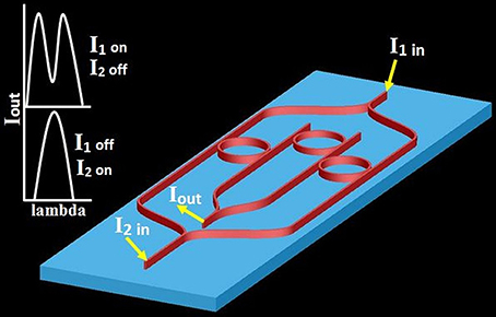
Figure 1 shows a 3D schematic model of the micro-ring configuration used to realize the optical switch. SOI technology, using the 130 nm rib waveguide and 90 nm slab fabrication process, was adopted for the model in the simulations. Each of the micro-rings has a radius of 10 μm and all waveguide widths are 400 nm. The light is introduced into and extracted out of the waveguides by integrated grating couplers [17, 18]. The silicon slab and waveguides are fabricated on top of a 2 μm silicon dioxide (SiO2) buried oxide (BOX) layer. A 1 μm SiO2 buffer layer is deposited on top of the silicon micro-rings and waveguides to provide thermal isolation from ambient temperature changes. The coupling gaps for the two outer rings are 270 nm while the coupling gaps for the central ring is 250 nm. A beam propagation method (BPM) was used to collect the dispersion data (effective and group effective index) and the ring loss and through transmission coefficient data. The data extracted from the BPM simulations were applied to a MATLAB program to show the spectral and intensity response of the optical switch. A finite difference time domain (FDTD) simulation was applied to the model to establish the validity of the equation describing the output function.

Figure 1. Schematic 3D representation of the photonic switch. The figure includes the output spectral content as a function of the input state of the controlling SLD's. The blue and red colors are shown to clearly differentiate the silicon slab (blue) from the waveguides (red). The BOX layer and SiO2 cover layers have been omitted for model clarity.
Switch States
The Switch “ON” State
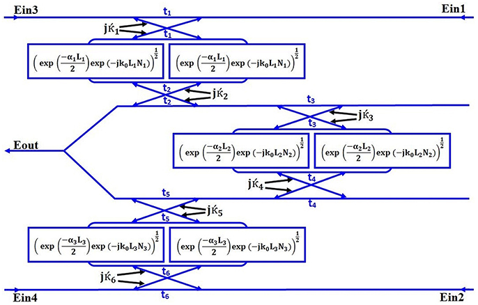
The broadband source “on” superluminescent diode (SLD) light is divided equally by a Y-splitter and is applied to the Ein3 and Ein4 inputs (see Figure 2). The “off” state SLD is in the off state so Ein1 and Ein2 = 0.

Figure 2. The mathematical model of the switch. The input Y-splitters are omitted to give a greater clarity to the model.
The Switch “OFF” State
The Broadband source “off” SLD light is divided equally by a Y-splitter and is applied to the Ein1 and Ein2 inputs. The “on” state SLD is in the off state so Ein3 and Ein4 = 0.
The Mathematical Model to Formulate the Combined Drop Output Equation
The output equation for the model of Figure 1 was derived using Mason's Rule. The mathematical representation of Figure 1 is shown in Figure 2.
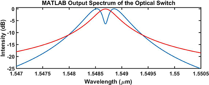
In the model of Figure 2, electric fields are used instead of intensities. The electric fields are applied throughout the development of the output equations. The output equation in the MATLAB program is processed as an intensity which provides the results for the MATLAB generated spectral outputs shown in Figure 3, section Discussion and Results.
Using Mason's Rule:
The loops are:
α is the ring absorption coefficient, t is the ring transmission coefficient, N is the group effective index, k0 is the free space wave vecor, L is the ring length.
The determinant is:
The cofactors are:
The forward path P1−1 due to Ein1 (traversing L1, L2) to the combined drop output is:
The forward path P1−2 due to Ein1 (traversing L1, L2, L3,) to the combined drop output is:
The forward path P2−1 due to Ein2 (traversing L3, L2,) to the combined drop output is:
The forward path P2−2 due to Ein2 (traversing L3, L2, L1,) to the combined drop output is:
The forward path P3 due to Ein3 (traversing L1) to the combined drop output is:
The forward path P4 due to Ein4 (traversing L3) to the combined drop output is:
The equation for the combined drop output is:
The FDTD Simulation
Two FDTD simulations were undertaken. One simulation was undertaken for the Iin1 SLD excitation = on and Iin2 = off. A second simulation was undertaken for the Iin2 SLD state = on and Iin1 state = off. Each simulation ran for 26 h and were undertaken using a workstation computer which had an 8 micro-processor cluster with each processor operating at 3.6 GHz. The system memory was 32 GB.
Discussion and Results
Switch Output Spectra
Figure 3 shows the output at the combined drop port (Iout) for the two states of the switch. The red spectrum represents the “on” state of the switch at a resonant wavelength of 1.5487 μm. Removing the “on” SLD source and applying the “off” SLD source introduces an optical transparency [19, 20] into the combined drop output spectrum and this is shown in Figure 3 by the blue spectrum. The blue spectrum exhibits a minimum at a resonant wavelength of 1.5487 μm. The transparency minimum intensity (−6.41 dB) can be adjusted by changing the coupling gaps in the design process. A finite minimum of the transparency gives the switch an error detection capability. If the “off “SLD fails, the output intensity is zero or the system noise floor intensity. The transparency minimum also gives the switch a capability to enhance the switch signal to noise ratio. As the minimum “off” intensity can be designed into this switch, the extinction ratio is adjustable. It is assumed that the extinction ratio references the difference between the energy of the positive level (transmitted 1) and the negative level (transmitted 0). In the case of Figure 3, the spectra show shows a design output “off” intensity for a worst case scenario design where there would be a substantial noise floor element. The design which exhibits a worst case extinction ratio of −6.4 dB, shown in Figure 3, could easily be adjusted and improved to a target on/off (extinction) ratio of −20 dB. The transparency minimum may be adjusted to clear the noise floor maximum of the measurement system thereby improving the signal to noise of the system.
The Generation of the Optical Transparency
One method used to introduce an optical transparency into a micro-ring resonator output spectrum, is to generate contra-rotating modes within the micro-ring cavity which results in a split resonance in the output spectrum. The contra-rotating modes may be induced by imperfections in the micro-ring or by optimizing the waveguide-to-ring coupling coefficients in a dual-ring coupled system. In the current work, the transparency is generated by the phase relationship that exists between the three micro-rings. A description of the difference between a contra-rotating induced transparency and the phase-coherent induced transparency is given in the author's previously published work [21].
Comparison of the Transfer Function Model With the FDTD Model
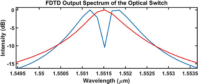
Figure 4 shows the FDTD output spectra generated for the two input states of the SLD's.
The blue spectrum represents the off state of the switch while the red spectrum represents the on state of the switch. The 3D simulation results of Figure 4, validate the formulation and use of the output equation (Equation 1) formulated from the mathematical model of Figure 2. The minimum of the transparency in Figure 4 is at a resonant wavelength of 1.55152 μm. Comparing the resonant wavelengths of the transparency minima in Figures 3, 4, there is a 0.18% difference in resonant wavelength between the FDTD and MATLAB generated output spectra.
Ring Size Fabrication Tolerance Error Correction
If the switch waveguide dimensions are undersized or oversized as a result of fabrication errors, the phase coherence between the rings will be compromised. This, results in an incorrect phase relationship between the rings and the effectiveness of the transparency would be lost. There are methods which can be used to mitigate fabrication tolerance errors and thereby overcome the problematic manifestations of a ring-to-ring phase mis-match. One remedial method is to fabricate heaters above the micro-rings to change the optical length of the rings [22] and to operate the rings at an elevated temperature above ambient. The elevated heater temperature allows the correction of the phase mis-match by reducing or increasing the heater temperature. One drawback of using an integrated heater for phase compensation is the quiescent operating power required. If using a heater compensated optical switch in a switch matrix, the power used could soon become excessive. Post-fabrication-trimming (PFT) [23–25] is alternative technique which can be used to permanently trim the effective index of the micro rings at the production stage. The PFT compensates for fabrication errors by permanently changing the RI of the waveguide or cladding material which changes the optical length of the waveguide.
Conclusions
An alternative method has been used to realize the all-optical switch using silicon-on-insulator technology. This unique approach to realize the optical switch does not use extrinsic methods, such as electro-optics or thermo-optics and so is a simpler and therefore less expensive method of optical switch fabrication.
The 3D FDTD simulation outputs gave validity to the spectral outputs produced by the application of the derived output equation. The power and the switching characteristics of the switch are a function of the switching physics and power requirements of the excitation SLD's. The successful application of the switch is only constrained by the realization of an efficient and repeatable post-fabrication-trimming technique and on the switching performance of the SLD's. Both the latter and former technologies are continually evolving and the advances in these technologies would enhance the evolution and the viability of the current switch design. The switching approach presented in this paper, hopefully, will provoke research into similar design methodologies as the use of alternative optical switching and interconnect technologies becomes a design necessity rather than a design choice.
Author Contributions
JL was solely responsible for the physical design concept of the novel switch and all mathematical simulations, derivations, and MATLAB coding.
Conflict of Interest Statement
The author declares that the research was conducted in the absence of any commercial or financial relationships that could be construed as a potential conflict of interest.
Acknowledgments
I would like to thank everyone who has given me the motivation to continue my research as an independent researcher.
MATLAB program and dispersion data available at: https://figshare.com https://figshare.com/s/2429e40b9ec6532497f5
References
1. Plößl A, Kräuter G. Silicon-on-insulator: materials aspects and applications. Solid State Electron. (2000) 44:775–82. doi: 10.1016/S0038-1101(99)00273-7
2. Mazuré C, Celler GK. Advanced electronic substrates for the nanotechnology era. Electrochem Soc Interface (2006) 15:33–40.
3. Wen YH, Kuzucu O, Hou T, Lipson M, Gaeta AL. All-optical switching of a single resonance in silicon ring resonators. Opt Lett. (2011) 36:1413. doi: 10.1364/OL.36.001413
4. Beata G, Andrzej M. Capsaicin Sensitive Neural Afferentation Gastrointest Tract from Bench to Bedside. Japan: World's largest Science, Technology & Medicine Open Access book publisher (2010).
5. Tassaert M, Roelkens G, Thourhout D Van, Baets R. All-Optical Low-Power Switch Based on III-V/SOI Heterogeneous Integration. Belgium (2009) p. 4–5.
6. Maldonado TA. Electro-Optic Modulators. Available online at: http://www.photonics.intec.ugent.be/education/IVPV/res_handbook/v2ch13.pdf
7. Tanushi Y, Yokoyama S. Design and simulation of ring resonator optical switches using electro-optic materials. Jpn J Appl Phys Part 1 Regul Pap Short Notes Rev Pap. (2006) 45:3493–7. doi: 10.1143/JJAP.45.3493
8. Watts MR, Sun J, DeRose C, Trotter DC, Young RW, Nielson GN. Adiabatic thermo-optic Mach–Zehnder switch. Opt Lett. (2013) 38:733. doi: 10.1364/OL.38.000733
9. Mingaleev S, Sokolov E, Richter A, Koltchanov I, Farina J. Induced transparency in double-ring photonic switches for optical networks-on-chip. In: Photonic Switch Using CRIT Effect. Norwood, MA (2014) p. 29–30.
10. Brosnihan TJ, Brown SA, Brogan A, Gormley CS, Collins DJ, Sherman SJ, et al. Optical IMEMS® - A fabrication process for MEMS optical switches with integrated on-chip electronics. In: TRANSDUCERS 2003 - 12th Int Conf Solid-State Sensors, Actuators Microsystems, Dig Tech Pap (2003) p. 1638–42.
11. Han S. Highly Scalable Silicon Photonic Switches Based on Waveguide Crossbar with Movable Waveguide Couplers. (2014) Available online at: http://escholarship.org/uc/item/85x7924r.pdf
12. University L. An Introduction to MEMS (Micro-Electromechanical Systems). Loughborough: Prime Faraday Partnership (2002).
13. Meng Y, Lu R, Shen Y, Liu Y, Gong M. Ultracompact graphene-assisted ring resonator optical router. Opt Commun. (2017) 405:73–9. doi: 10.1016/j.optcom.2017.07.084
14. Kim JT, Chung KH, Choi C-G. Thermo-optic mode extinction modulator based on graphene plasmonic waveguide. Opt Express (2013) 21:15280. doi: 10.1364/OE.21.015280
15. Yu L, Shi Y, Dai D, He S. Energy-Efficient Tunable Silicon Photonic Micro-Resonator with Graphene Transparent Nano-Heaters. Ithaca, NY: ARXIV (2015).
16. Plander I, Stepanovsky M. MEMS optical switch : switching time reduction. Open Comput Sci. (2016) 6:116–25. doi: 10.1515/comp-2016-0010
17. Gal JV. Addressing Fiber-to-Chip Photonics Jose Vicente Gal'. Philosophy (2010). doi: 10.4995/Thesis/10251/9196
18. Vivien L, Pascal D, Lardenois S, Marris-Morini D, Cassan E, Grillot F, et al. Light injection in SOI microwaveguides using high-efficiency grating couplers. J Light Technol. (2006) 24:3810–5. doi: 10.1109/JLT.2006.878060
19. Zheng Y, Yang J, Shen Z, Cao J, Chen X, Liang X, et al. Optically induced transparency in a micro-cavity. Light Sci Appl. (2016) 5:e16072. doi: 10.1038/lsa.2016.72
20. Cui D, Xue C, Liu C, Wei L, Wang Y, Liu J. Induced-transparency in silicon-on-insulator based novel resonator systems. In: Annual IEEE International Conference on Nano/Micro Engineered and Molecular Systems NEMS. Taiyuan (2013) p. 582–5.
21. Lydiate J. Modelling and simulation of a thermally induced optical transparency in a dual micro-ring resonator. R Soc Open Sci. (2017) 4:170381. doi: 10.1098/rsos.170381
22. Fegadolli WS, Vargas G, Wang X, Valini F, Barea LAM, Oliveira JEB, et al. Reconfigurable silicon thermo-optical ring resonator switch based on Vernier effect control. Opt Express (2012) 20:14722. doi: 10.1364/OE.20.014722
23. Schrauwen J, Van Thourhout D, Baets R. Trimming of silicon ring resonator by electron beam induced compaction and strain. Opt Express (2008) 16:3738. doi: 10.1364/OE.16.003738
24. Milosevic MM, Chen X, Cao W, Runge AFJ, Franz Y, Littlejohns CG, et al. Ion implantation in silicon for trimming the operating wavelength of ring resonators. IEEE J Sel Top Quantum Electron (2018) 24:8200107.
Keywords: photonic, optical, switch, micro-ring, resonator, transparency
Citation: Lydiate J (2018) Modeling and Simulation of the Intrinsic Function of a Photonic Switch. Front. Phys. 6:60. doi: 10.3389/fphy.2018.00060
Received: 03 April 2018; Accepted: 31 May 2018;
Published: 19 June 2018.
Edited by:
Derek Abbott, University of Adelaide, AustraliaReviewed by:
Junichi Fujikata, Photonics Electronics Technology Research Association, JapanWeiqiang Ding, Harbin Institute of Technology, China
Copyright © 2018 Lydiate. This is an open-access article distributed under the terms of the Creative Commons Attribution License (CC BY). The use, distribution or reproduction in other forums is permitted, provided the original author(s) and the copyright owner are credited and that the original publication in this journal is cited, in accordance with accepted academic practice. No use, distribution or reproduction is permitted which does not comply with these terms.
*Correspondence: Joseph Lydiate, am9lLmx5ZGlhdGVAYW9sLmNvLnVr
 Joseph Lydiate
