
95% of researchers rate our articles as excellent or good
Learn more about the work of our research integrity team to safeguard the quality of each article we publish.
Find out more
ORIGINAL RESEARCH article
Front. Aerosp. Eng. , 30 March 2023
Sec. Energetics and Propulsion
Volume 2 - 2023 | https://doi.org/10.3389/fpace.2023.1152429
This article is part of the Research Topic Pressure Gain Combustion Technologies for a Greener Propulsion View all 4 articles
Propulsion systems based on the constant-pressure combustion process have reached maturity in terms of performance, which is close to its theoretical limit. Technological breakthroughs are needed to develop more efficient transportation systems that meet today’s demands for reduced environmental impact and increased performance. The Rotating Detonation Engine (RDE), a specific implementation of the detonation process, appears today as a promising candidate due to its high thermal efficiency, wide operating Mach range, short combustion time and, thus, high compactness. Following the first proofs of concept presented in the 1960s, the last decade has seen a significant increase in laboratory demonstrators with different fuels, injection techniques, operating conditions, dimensions and geometric configurations. Recently, two flight tests of rocket-type RDEs have been reported in Japan and Poland, supervized by Professors Kasahara (Nagoya University) and Wolanski (Warsaw University), respectively. Engineering approaches are now required to design industrial systems whose missions impose efficiency and reliability constraints. The latter may render ineffective the simplified solutions and configurations developed under laboratory conditions. This requires understanding the fundamentals of detonation dynamics relevant to the RDE and the interrelated optimizations of the device components. This article summarizes some of the authors’ experimental and numerical work on fundamental and applied issues now considered to affect, individually or in combination, the efficiency and reliability of the RDE. These are the structure of the detonation reaction zone, the detonation dynamics for rotating regimes, the injection configurations, the chamber geometry, and the integration constraints.
The Chapman-Jouguet (CJ) and Zel’dovich-Von Neuman-Döring (ZND) models define the ideal detonation as a supersonic combustion wave with a constant-velocity planar front and a one-dimensional reaction zone that reaches chemical equilibrium at the same position where the condition for self-sustainability is met. These models determine the ideal characteristics of self-sustained detonations, such as the maximum pressure and propagation velocity. Detonation dynamics are observed under propagation constraints that prevent the satisfaction of at least one of these conditions. Physically, self-sustainment in detonation dynamics is an example of sonic choking, which expresses that detonation propagation has become independent of its initiation processes. The sonic locus is the head of the expansion wave propagating behind a self-sustained wave front. Choking keeps the expansion head far enough away from the reaction zone to allow chemical reactions to progress sufficiently. For example, transverse expansion of the reactive flow slows the temperature rise and hence the chemical transformation, and curves the leading shock of the detonation, reducing its velocity and possibly leading to localized successive quenching and re-ignition. Detonation devices usually make it difficult to achieve the CJ and ZND optimums. Their performance characteristics are lower than estimated from the ideal characteristics, with typical detonation velocities 20% lower than the CJ velocity (DCJ). These models should rather be considered as theoretical thermodynamic limits, useful for calibrating constitutive relations and obtaining easily representative orders of magnitude. Some causes of non-ideality in RDEs are imperfect mixing of the propellants and their dilution with hot gases (Section 2), the curvature of the chamber, too narrow a chamber width for the annular configuration of the RDE, the curved shape of the detonation front and its oblique orientation relative to the direction of rotation, wall losses due to friction and heat transfer, and propellant consumption by deflagration. Some basic experimental and numerical works on detonation dynamics in curved chambers and their relations to the local dynamics of the detonation reaction zone are described below.
Detonation waves in gases are inherently unstable and exhibit a complex cellular structure first identified in the late 1950s (Denisov and Troshin, 1959; Denisov and Troshin, 1960). A cellular detonation front is a grouping of Mach waves consisting of shocks propagating in the transverse directions and others in the longitudinal direction. The classical recording technique uses soot-coated plates, based on the erosion of the coating by the continuous interaction of the transverse and longitudinal shocks. The thermodynamic state at the interaction locus is very different from the ZND average shock state, and the soot-plate technique takes advantage of the higher magnitude of the pressure. Plates positioned along the walls of a detonation tube provide a history of the shock interactions between themselves and the walls, showing diamond-shaped cell traces, e.g., Figure 1A. Frontal impacts on a plate facing the direction of propagation provide frontal views of the transverse shocks, showing polygonal cell patterns, e.g., Figure 1B. The velocity of the forward-propagating shocks varies around the mean detonation velocity, such as DCJ (Van Tiggelen and Libouton, 1989). The boundaries of the polygonal patterns are the intersections of the forward waves with the transverse waves sweeping the surfaces of the slower forward waves. Thus, the combustion rate is much faster behind the transverse waves and the faster forward waves as shown by high-speed PLIF recordings, e.g., (Pintgen, et al., 2003; Pintgen and Shepherd, 2003; Austin, et al., 2005; Frederick, et al., 2022). The cellular reaction zone is thus a distribution of ignition and failure loci of chemical reactions that depends on the cross-section area of the tube and the mixture composition and initial pressure.
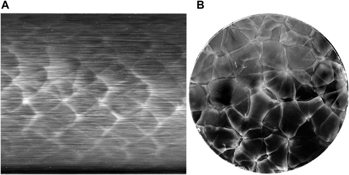
FIGURE 1. Soot recordings showing a longitudinal (A) and a front-view (B) of a cellular detonation front in the 2H2 + O2 + 2 Ar mixture at initial pressure 22.5 kPa propagating in a 56-mm wide round tube (Monnier, et al., 2022).
Typically, longitudinal recordings in square or rectangular tubes have been used to categorize the diamond-shaped cell traces as very regular, regular, irregular and very irregular (Strehlow, 1969; Libouton, et al., 1981) depending on whether the standard deviation of the diamond widths is very small or at least as large as the mean width. Regular diamonds are observed for mixtures with light fuels and oxygen and high dilution by a monoatomic inert gas, typically argon, and these mixtures are referred to as stable. Irregular diamonds are observed for mixtures with heavier fuels and dilution with nitrogen, and these mixtures are referred to as unstable (Austin, et al., 2005; Desbordes and Presles, 2012; Jackson & Short, 2013; Zhao, et al., 2016). This regularity is interpreted based on the chemical kinetics and the ZND model. Short and Sharpe (2003) and Radulescu, et al. (2013) showed that irregularity could be associated with larger ZND induction thicknesses with respect to the complete reaction length. They propose a regularity criterion involving the ratio of the former to the latter (the χ number): the larger χ, the more irregular the diamonds (the more unstable the mixture). These interpretations are based on chemical kinetics whereas the shape of the cross-section of the detonation tube also determines the behaviors and the dimensions of the detonation cells (Monnier, et al., 2022).
Detonation propagation is referred to as multicellular or marginal depending on whether the number of cells on the front surface is large or limited. The frontal views of multicellular detonations, e.g., Figure 1B (Monnier, et al., 2022), (Monnier, et al., 2023), show that the cellular patterns are irregular if the number of cells on the front is sufficiently large. For marginal detonations, the shape and dimensions of the cells can be strongly dependent on the shape of the tube cross section. Thus, rectangular front-view cellular patterns are observed only in tubes with rectangular cross-section (Hanana, et al., 1998), and the marginal detonation regimes in stable mixtures are different depending on the tube cross-section shape. Given the tube dimension and the mixture, the mean cell width decreases with increasing the initial pressure, which, therefore, is the usual control parameter for selecting marginal or multi-cellular detonation regimes.
This raises questions about the ability of longitudinal recordings alone to characterize the cell structure, compared to the information provided by front-view recordings, and thus the relevance of a single length. The longitudinal recordings provide only local information, which certainly includes how the Mach wave fronts interact with each other but also with the walls. Any physical representation of this irregular structure should be three-dimensional, and a topic of debate is whether a unique characteristic length is relevant to characterize a 3D cell.
Therefore, the one-dimensional steady-state reaction zone induced by the leading shock of the ZND model can only be considered as a representative average of the three-dimensional cellular process if the initial pressure and temperature of the gas make the detonation cells small compared to the transverse dimensions of the tube.
Nevertheless, the mean cell width derived from the longitudinal recordings is a length commonly used to characterize the cell structure. One practical interest is in the pre-dimensioning of devices where detonation dynamic behaviors may occur. Indeed, the cell width of the multicellular detonation often correlates well with the characteristic dimension of the device. The ZND chemical length and time are easy to calculate and correlate reasonably well with the mean cell width. A physical description of the reaction processes requires detailed chemical kinetic schemes calibrated for the high temperatures and pressures relevant to detonation reaction zones. This is the subject of fundamental studies and a difficult problem. The ZND chemical length and time are sensitive to the chemical scheme considered, so some caution is required when using them to estimate the mean cell width from existing correlations. Hydrodynamics and chemical kinetics are the necessary modeling ingredients for the propagation of cellular detonations in tubes whose transverse dimensions are sufficiently large compared to the mean cell width. This implies no significant influence of diffusive effects, such as boundary layers and turbulence.
From a theoretical point of view, the actual mechanisms that make the theoretical ZND 1D planar steady-state reaction zone unstable are still under investigation. Analyses consider this steady state as the origin of linearly growing small perturbations, and their goal is to select the unstable modes that should evolve into transverse waves in the limits of long times and large transverse dimensions of the channel in which the detonation propagates, e.g., (Clavin and Searby, 2016). These limits are difficult to estimate because the number of unstable modes increases with the transverse dimensions. Another model combining graph theory and statistics is being investigated (Monnier, et al., 2023). Such approaches can predict mean cell widths, but their ability is limited by the values of their assumptions, a point, that is, difficult to assess, and by those of the chemical kinetic schemes. Numerical simulations get around the difficulty of the assumptions on the fluid dynamics by running the computation long enough so that the small perturbations from the initial conditions have stabilized into statistically identical detonation cells given the boundary conditions. However, they still require large computational resources and reliable chemical kinetic schemes, e.g., (Crane, et al., 2022), to realistically account for the fundamental interplay of inviscid compressibility, chemical kinetics, and tube cross-section shape even for the simple propagation of cellular detonation. Nevertheless, considering that most practical problems also include ignition, quenching, heat transfer and deflagration, numerical simulation should be the preferred tool for a coherent combination that includes at least diffusive effects. Numerical simulations currently rely on reduced-order models and interpolations of a large amount of experimental data. Today, it is unclear when a numerical tool will be able to predict without or with a limited preliminary experimental base the necessary information for the complete design and dimensioning of operating equipment. As for RDE simulation, the underlying question is which characteristic length scales are relevant for design, from the internal structure of the detonation reaction zone to the chamber dimensions. Thus, a preliminary selection of the essential physical phenomena can help to separate difficulties. For example, numerical simulations of injection devices that improve the mixing of the fresh gases show improved properties of the detonation without resolving its cellular structure (Section 2).
RDE chambers can be annular, i.e. with a cylindrical center body, e.g., (Nicholls et al., 1966; Wolanski, 2013; Frolov et al., 2015), hollow (i.e. without a center body), e.g., (Tang et al., 2015; Anand et al., 2016), or semi-hollow, (i.e. with a conical center body), e.g., (Bykovskii and Vedernikov, 1996; Lin et al., 2015; Zhang et al., 2017; Hansmetzger et al., 2018). Detonation behavior in curved confinements also concerns the safety of industrial facilities. Laboratory setups are limited to planar or axisymmetric geometries, the design of which may also limit the detonation dynamics to 2D behavior. In a typical annular RDE chamber, the rotating detonation wave front is a three-dimensional surface due to the transverse expansion of the flow in the azimuthal and axial directions, the interaction of the front with the curved walls, and the heterogeneities of the fresh mixture. Nevertheless, the compilation of the front dynamics observed in model configurations reveals useful qualitative trends depending on the dimensions and shapes of the channels or chambers.
Short et al. (2018); Short et al. (2019) experimentally and numerically studied the dynamics of detonation propagation in a constant cross-section, two-dimensional circular arc of high and gaseous explosives. With increasing arc thickness, they observed a monotonic increase in the angular velocity of the detonation, up to a certain limit and the formation of a Mach stem, which disappeared for sufficiently wide arcs.
Edwards et al. (2018) experimentally studied detonation propagation in curved channels with rectangular cross-sections. They observed Mach stems with maximum Mach number along the outer (concave) wall. They successfully compared their experimental results with numerical modeling based on the Geometrical Shock Dynamics technique (Whitham, 1974). Thomas and Williams (2002) also observed a Mach stem moving along the outer wall of their curved channel using schlieren and soot recordings, with more stable detonation transmissions for larger bend curvatures and initial pressures.
Kudo et al. (2011); Nakayama et al. (2012); Nakayama et al. (2013) experimentally studied detonation propagation in a circular channel with an angular span of 3/4 of 2π rad. The detonation was transmitted from a tube with the same rectangular cross-section as the channel. They collected data for several mixtures and initial pressures p0. They identified three modes with increasing p0, namely 1) a subcritical (unstable) mode, with successive complete quenching and re-ignitions, 2) a critical mode, with successive local quenching and re-ignitions near the inner wall, and 3) a supercritical (stable) mode, with continuous multicellular structure and CJ velocity of the detonation front. Their analysis leads to the criterion Ri / λ > 23 for the observation of stable propagation, where Ri denotes the inner channel radius and λ the mean width of the detonation cells.
Rodriguez et al. (2019); Melguizo-Gavilanes et al. (2021) experimentally and numerically studied detonation propagation along the outer wall of a circular hollow chamber with an angular span of 3/4 of 2π rad. A CJ detonation was transmitted from a straight channel, so that the detonation, which then possibly propagated along the chamber wall after diffraction, was semi-confined, outwardly by the rigid outer wall of the chamber and inwardly by the fresh gases pre-compressed by the shock resulting from the diffraction. They identified three propagation modes, all starting with a Mach stem, i.e., the irregular oblique reflection of the initial detonation. With increasing p0, they observed 1) a subcritical unstable mode, with successive quenching and re-ignition and finally complete quenching, 2) a critical stable mode, with a steady rotation of the Mach stem (constant angular velocity and constant stem height less than the chamber radius, e.g., Figure 2 and Figure 3 a supercritical unstable mode with a regular oblique reflection of the cellular detonation that eventually propagated throughout the volume. The critical stable detonation is overdriven (D/DCJ > 1) and, therefore, has very small cells compared to those on a CJ front. This steadily-rotating overdriven Mach detonation was observed with an outer diameter smaller than the minimum value for stable rotation in a circular channel defined from the inner diameter and the channel width by the above criterion. These observations are also consistent with experimental results showing that hollow and semi-hollow RDE chambers have improved properties for rotating detonations compared to annular chambers.
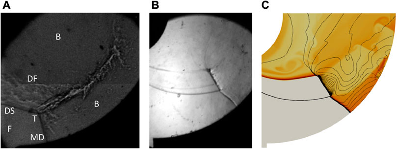
FIGURE 2. (A) Schlieren picture of a clockwise-rotating Mach detonation. (F): fresh gas, (B): burnt gas, (T): triple point, (MD): Mach detonation, (DS): diffracted shock, (DF): deflagration (Rodriguez, et al., 2019). Clockwise-rotating Mach detonation: comparison of an experimental image (B) and a simulated flowfield (C) (Rodriguez, et al., 2019; Melguizo-Gavilanes, et al., 2021).
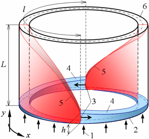
FIGURE 3. RDC operating principle. 1—direction of injection; 2—combustor inlet; 3—RDs; 4—fresh mixture layer; 5—oblique shocks; 6—combustor exit; h—height of RDs front, maximum thickness of the mixture layer; l—azimuthal period between two RDs; L—length of the combustor.
Overall, these works suggest that the larger the outer radius, the closer the wave dynamics is to the ideal CJ-ZND properties, while a too-narrow a channel results in unstable rotation. The hollow and semi-hollow configurations appear to produce higher pressures and rotation velocities, e.g. (Hansmetzger et al., 2018; Schwer et al., 2020) which may reflect the undersizing of laboratory demonstrators with annular chamber. Thus, global geometric effects on the rotation dynamics appear to predominate over the local properties of the detonation reaction zone.
These observations suggest that the relevant length scales for dimensioning RDE chambers are essentially related to the expansion of the detonation products and the mixing of the fresh gases, and to a lesser extent to the local cellular dynamics of the reaction zone. In fact, the correlations often show a large ratio of the characteristic length of the device to the mean cell width, typically 10–50, although their relevance and accuracy can be criticized. As for any detonation device, larger dimensions seem to be more favorable to obtain performance characteristics (velocity, pressure impulse) closer to the ideal values given by the CJ and ZND models. Technological constraints are intrinsic causes of non-idealities and thus of degraded performance. The first cause is an incompatibility between the total mass flow rate and the chamber dimensions. Too low rates result in instabilities and a low operation pressure if the chamber dimensions do not fit the increased detonation characteristic length. Deflagration then becomes a strong factor consuming the fresh mixture and deteriorating its quality. Too high rates can lead to initiation of multiple detonations in the fresh mixture layer under increased operational pressure, so the mixing time can be the limiting factor for the combustion efficiency. Chamber widths or outside diameters that are too small will result in excessive losses, either adiabatic losses due to transverse flow expansion or non-adiabatic losses due to heat transfer. The second cause is injection technology. Solutions based on premixed injection are favorable for higher performance but not for safety. Non-premixed injection (Section 3) can result in mixing times greater than the characteristic cell time or even the detonation rotation time. Careful tuning of the injection configuration and mass flow rates is therefore required, but faces the difficulty that their best combination may have a narrow efficiency range and depend on the chamber geometry.
In most practical situations involving detonations, the initial state of the reactive gas is non-uniform. The explosive mixtures can be unintentional, such as the cloud formed in atmospheric air with a combustible leaking from a tank or a pipe. They can be intentional, such as those in the model configurations of research works or defense and propulsion applications, for example, RDEs. For safety reasons, the fuel and the oxidizer are injected separately into the chamber, and their mixing time may not be short enough, compared to the rotation time of the detonation and the exhaust time of the burnt products. The mixing of the fresh gases with the residue of the detonation products from the previous cycle also contributes to the formation of a non-uniform composition, which is considered to be partly responsible for the performance deficit observed between measurements and models.
The operating principle of an RDC (Rotating Detonation Combustor) is shown schematically in Figure 3. The combustor is a cylindrical annular channel.
The propellant 1) is continuously injected through holes or slots in the injector wall 2), depending on the configuration, which forms a layer of fresh mixture 4) with a cross section sufficient for the stable propagation of an RD (Rotating Detonation). After initiation, one or more RDs 3) settle in the combustor and propagate in the azimuthal direction x. The layer of mixture consumed by an RD is renewed during the period between two successive passages of a RD. The RD propagation can thus be continuous and stable over time with an operation frequency of several kHz, a constant spatial period, l, between the RDs and a constant height, h, of the RD fronts. The high-pressure combustion products generated by the RDs (in red) expand in the channel before being ejected from the combustor 6). Under these conditions, oblique shocks 5) are formed as a continuation of the detonation waves in the burnt gases.
In an RDC, fuel and oxidizer can be technically injected either premixed or separately. Theoretically, a clear advantage of the fully-premixed injection is the ability to achieve complete combustion and to obtain the highest compression by detonation. To reach this goal, it is also necessary to create a continuous fresh layer with good filling of the radial section of the combustor, minimum pressure loss and low dilution of the fresh reactants by the hot combustion products.
However, it is generally accepted that premixed injection would be difficult to realize in practice. The main risks that should be tackled are the hot-gas feedback in the injector due to deflagration propagation, when the back pressure in the combustor is higher than in the supply lines, and detonation transmission through the injector orifices. The latter is the most important risk because it can cause operation failure or even mechanical damage to the feed system. To mitigate these risks, one possibility is to make the orifices smaller than the critical size that allows transmission. This would result in a high loss of injection pressure but also technological problems due to a large number of tiny openings.
Despite all these challenges, some experimental investigations were conducted by Andrus et al. (2015) to explore the possibility of direct injection of premixed propellants in an RDC. These experiments first focused on a sonic flame to simulate the effect of detonation propagation through a series of injection nozzles. In each test, a flashback was observed in the premix supply lines, despite the choice of a small diameter for the injection nozzles. A technique was then proposed to prevent flashback based on the control of boundary layers and flame arresting properties in the premix injection tubes (Andrus et al., 2017a). The goal was to at least stabilize a flame under burner conditions at the exit of the nozzles. The application to an RDC proved fruitful since the RDs could be maintained in the combustor (Andrus et al., 2017b). However, the propagation velocity was still far from the theoretical expectations (40%–60% of the CJ velocity for a C2H4/air mixture close to stoichiometry) due to the excessive consumption of fresh mixture by deflagration. This technique still needs to be adapted to the mixtures and the geometries. In particular, the authors suggested adjusting the mixing delay in the channel upstream of the injection nozzles, in order to reduce the deflagration losses while maintaining a good quality of the fresh mixture.
In the early 2D numerical simulations, premixed injection was mainly considered to demonstrate RDC operation under ideal conditions (Davidenko et al., 2007; Zhdan et al., 2007; Hayashi et al., 2009; Schwer and Kailasanath, 2010; Yamada et al., 2010; Stoddard et al., 2014). The injection was often assumed to be uniformly distributed by using a specific injection model as a boundary condition (Hishida et al., 2009). More complex 3D computations were also performed but detonation transmission is artificially prevented within the injector (Kobiera et al., 2009). The RDC was also an interesting framework to implement and test the Adaptive Mesh Refinement (AMR) method to dynamically adjust the mesh resolution following the RD propagation (Eude et al., 2011).
According to recent numerical simulations with various geometries of annular injection slots for premixed injection, the shape of the fresh mixture layer can be very different (Zheng et al., 2020). Secondary shocks can occur, leading to wave reflections at walls and complex wave structures. Even if the mixing between the fresh gases is perfect, the radial gap between the chamber walls cannot be completely filled with the fresh mixture unless the slot section is severely restricted. Deflagration losses in the fresh mixture layer prior to detonation have been numerically evaluated to be about 30% of the injected mass, considering premixed injection through holes (Gaillard et al., 2017).
Separate injection of fuel and oxidizer is commonly used in RD experiments because of the problems associated with premixed injection mentioned above. In fact, detonation cannot be transmitted to the injector orifices, so their size should not be strictly limited. However, the advantage of premixed injection is lost. It is therefore necessary to ensure efficient and rapid mixing between the reactants to obtain the expected pressure gain from detonation. Typical configurations used experimentally for oxygen/fuel injection are represented by doublets (Bykovskii et al., 2008; Ishihara et al., 2017) or triplets (Le Naour et al., 2011) of holes, evenly distributed along the circumference.
The main difficulty in obtaining good quality mixing with separate injection is related to the short duration between successive detonation waves (typically tens of microseconds for oxygen) and the presence of hot combustion products within the mixing zone. In order to obtain a rapid mixing process, it is necessary to create conditions of intense turbulence, which causes negative effects such as total pressure loss and hot gas entrainment. The presence of hot gas between the fuel and the oxidizer provokes the formation of diffusion flame fronts that prevent the formation of a new mixture.
It is generally impossible to have the same parameters of the injected propellants due to their different natures and mass flow rates. For some injector configurations, such as doublet, this can result in propellant stratification in the mixing zone. Propellant with a higher velocity will have a higher concentration farther from the injector, creating a gradient of mixture fraction across the fresh mixture layer. A similar effect can occur in an airflow with transverse fuel jets.
Another important factor in separate injection is the blocking effect of the detonation wave on the fuel injection. The recovery of the propellant flow rate after a backpressure jump usually takes a different amount of time for each propellant, resulting in a temporal variation of the mixture ratio and additional propellant stratification within the fresh mixture layer.
As an intermediate type of injection, some researchers have proposed injector designs whose function is to partially premix the propellants prior to their injection in the combustor. A common idea is to bring the propellant flows into contact in restricted cross-section duct at some distance upstream of the combustor.
A first idea resulting of a jet-in-crossflow configuration was used by Rankin et al. (2017) for a full gaseous injection of air and hydrogen. A stable propagation regime was mostly observed with one wave, or even two co-rotating waves when the mass flow rate was increased, meaning that the mixing efficiency was sufficient to sustain the propagation. However, the propagation speed was about 60%–90% of the CJ velocity evaluated for the injected mixture conditions. Explanations for this deficit can be attributed to the curvature effect, compared to a theoretical 1D detonation, and also to mixture heterogeneities. According to the authors, a lower mixing efficiency could also be responsible for the unstable regime with two counter-rotating waves (Duvall et al., 2018). also observed a speed deficit of about 20% compared to the CJ speed for a similar injection configuration. Another study from Li et al. (2018) with an ethylene-air mixture showed a propagation speed of 67% of the CJ speed with the same injection configuration. It was then used for a liquid injection of Jet-A1 with air but was not really successful in obtaining detonation. The authors expressed the need to better characterize the mixture formation and also to properly design the injector (Zhou et al., 2019). Studied detonation propagation with the same injection in an experimental combustor with the purpose of turbine integration. The experiments performed with and without a guide vane at the combustor exit show an increase in the detonation speed with a guide vane. The guide vane restricts the exit section producing a pressure increase in the combustor. Thus, the injection velocity of the propellants is reduced, which should improve the mixing efficiency during the injection process.
A second concept, still based on a jet-in-crossflow configuration, was used by Kindracki et al. (2011) in their small chamber. It consisted of an axial oxygen injection through a slot and a radial fuel injection through outward-oriented orifices in a restricted area before the chamber section. The authors successfully obtained stable propagation speed of the detonation around 1,400–1,600 m/s, for gaseous mixtures of methane, ethane and propane with oxygen. The speed deficit compared to the CJ speed was not mentioned but it is around 40% for a methane-oxygen mixture under the same conditions. The authors suspected local mixing heterogeneities and also non-repeatable mixing processes between consecutive propagation cycles (Wen et al., 2019). Studied detonation propagation in an obround combustor fed with air through an axial slot and hydrogen through an outward-oriented radial slot. In this experimental configuration, the authors obtain a speed deficit of at least 15% compared to the theoretical CJ speed. In addition, the injection section is quite small compared to the combustor section, resulting in excessive pressure loss and incomplete filling of the combustor section.
A third type of injection deals with both axial injection for fuel and oxidizer. In Xu et al. (2022), oxygen-rich air is injected through a converging-diverging slot and liquid kerosene is injected at the throat of the slot through a circular array of atomizers. Two unstable propagation regimes were alternatively obtained: a single mode and a counter-rotating mode with two fronts. Reducing the cross-sectional area ratio between the throat and the combustor increased the occurrence of the counter-rotating mode, thus affecting the operation stability (Sun et al., 2019). Simulated air injection through a converging-diverging slot with hydrogen feeding holes distributed over the entire circumference of the combustor. The propellants meet in the diverging part of the air slot. Cases with different widths of the air slot throat were studied to see the effect on mixing and detonation speed. The case with the largest width improves the mixing efficiency but also reduces the detonation speed. It means that this geometric parameter affects other critical characteristics of the fresh mixture, more precisely the average pressure and temperature in front of a detonation. With another kind of axial injection configuration (Ma et al., 2019), tested experimentally an injection scheme with coaxial flows. The oxidizer is injected through the central tube and the fuel through the peripheral annulus. With 72 coaxial elements, the injection area is around 20% of the combustor cross-section area. The observed detonation speed deficit is about 25% with respect to the CJ speed. The authors suggest that even though the propellants meet upstream of the combustor, the mixing efficiency would not be high enough, creating propellant stratification during the injection.
Injection is one of the most important topics in relation with RDC operation. Thus, this subject has been studied at ONERA since 2013 by modeling and numerical simulations with the CEDRE code (Refloch et al., 2011). So far, these studies have consisted in designing and optimizing injection element configuration for non-premixed injection.
To simplify, the injector is considered as a regular arrangement of injection elements repeated periodically along the circumference and radius of the injector face (Figure 4A). Then, the mixing process with only one element (in black in Figure 4A) can be finely simulated with the LES approach (Figure 4B). This procedure can be used to study continuous injection in an established regime (Gaillard et al., 2015) or a transitory reinjection process between two RD passages with or without chemical reactions (Gaillard et al., 2019). As a first validation case shown in Figure 4C, simulation of RD propagation can be performed on a series of injection elements without curvature effects to make last improvements in the injector design and tune the numerical approach (Gaillard et al., 2017). Finally, a simulation of RD propagation in an annular RDC with definitive injector configuration can be performed to account for realistic loss factors such as heat transfer and friction on the walls (Figure 4D).
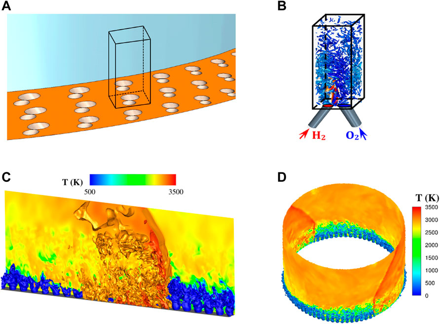
FIGURE 4. General approach for injection studies. (A) Definition of the injection elements composing the RDC injector, (B) precise computation on a fine mesh of the mixing interactions for an injection element, (C) simulation of the RD propagation on a linear series of injection elements, (D) simulation of the RD propagation in an annular RDC.
A first injection element studied at ONERA was the Semi-Impinging (SI) element. A schematic of the SI element, as well as an example of periodic arrangement of SI elements on the injector wall, are given in Figure 5. The SI element represents an intermediate configuration between the ones providing direct impact and purely shear interaction of unlike propellant jets. H2 and O2 jets first interact by impact close to the injection plane, then farther with the jets of neighboring elements due to flow shear and turbulence triggered by the impact. In the basic SI geometry, the O2 tube section is twice larger than the H2 one. The H2 tube diameter is around 1 mm. The angle between the jets is α = 30°, as a compromise between the needs to have an impact close to the injection wall, to obtain a compact injection element (considering geometric constrains on the feeding elements), and to preserve a high jet momentum along the combustor axis. The β and γ angles were defined to ensure injector feasibility, to avoid intersections between neighboring holes. A result of mixing simulation obtained for an established non-reactive injection regime (1 bar, 300 K, injection Mach number 0.7) is given in Figure 6A. It shows iso-surfaces of the Q-criterion colored by the local Equivalence Ratio (ER). Globally, it can be said that the SI element produces a low mixing efficiency close to the injection wall, and that the efficiency increases strongly above a distance of 5×dH2 from the injection wall as it can be seen in Figure 6C. The mixing efficiency, in a section Sy perpendicular to the y-axis, is given by the relation
for the mass flow rate

FIGURE 5. Design of the SI injection element (A), and scheme of a periodic pattern of SI elements on the injector face (B).
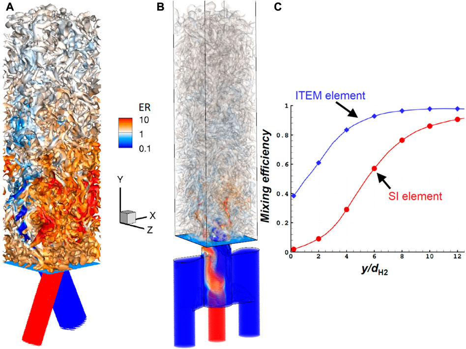
FIGURE 6. LES of established injection of gaseous H2 and O2 for the SI (A) and ITEM (B) injection elements. Turbulent structures are visualized by iso-surfaces of Q-criterion colored by Equivalence Ratio (ER). (C): Mixing efficiency profiles along the y coordinate normalized by the H2 tube diameter for the SI and ITEM elements.
Facing the lack of efficiency of the SI element, it was decided to design an improved injection element. An Injection To Enhance Mixing (referred to as ITEM element) for fuel-oxygen mixtures, has recently been patented by ONERA (Davidenko and Gaillard, 2022) and its geometry is shown in Figure 7. First, the propellants are fed through tubes (1 and 2) from manifolds not shown here. Oxygen is supplied by the lateral tubes 2) and the fuel by the central tube 1). Both propellants then enter a pre-chamber 4). The fuel flows axially while oxygen enters through opposite orifices (section H×L1) passing through lateral channels 3). Finally, both propellants are injected into the combustor through an orifice of diameter D in the injection wall 5). The main function of this ITEM element is to bring the propellant flows together within the pre-chamber and create developed contact surfaces by interpenetration. Partial mixing occurs as a secondary effect of the interaction of the propellant flows.
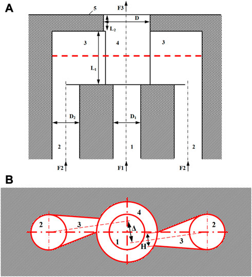
FIGURE 7. Design of the ITEM injection element with three feeding tubes (1, 2). (A) Section passing through the axes of the feeding tubes and normal to the injection wall (5), (B) section parallel to the injection wall in the middle of the pre-chamber (4).
The same type of non-reactive mixing simulation as for the SI element was carried out for the ITEM element and the resulting flow field is similarly pictured in Figure 6B. It can be seen in Figure 6C that for the ITEM element, the mixing efficiency is higher at the injector wall and reaches faster the top level. However, some heterogeneity remains just above the injection hole. Indeed, it is important to remember that the objective of the ITEM element is not to inject a full premix into the combustion chamber but to create the conditions for good contact between the reactants. Figure 8 shows that the propellants do not mix instantaneously, but the evolution of the contact surface suggests that turbulent mixing interactions are progressively triggered until the flow penetrates the combustion chamber.
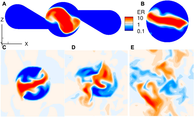
FIGURE 8. LES of established injection of gaseous H2 and O2 for the ITEM injection element. Fields of Equivalence Ratio in cross-sections at different distances from the injector face. (A): pre-chamber with lateral channels (y = −2 mm), (B): pre-chamber close to the exit (y = −1 mm), (C): injector face (y = 0), (D): combustion chamber close to the wall (y = 1 mm), (E): combustion chamber (y = 2 mm).
A simple case that can first be proposed to test the injection element design is a periodic RD propagation on a series of injection elements. This series of elements aligned in the RD propagation direction can represent a sector of an annular RDC, without taking into account the RDC curvature and the wall effects. The main interest of such simulations is to demonstrate that a stable RD propagation regime can be obtained and to evaluate the mixing quality and detonation velocity. The simulation results for a number of SI elements have been presented in (Gaillard et al., 2017).
A comparison is now made between the SI and ITEM elements in terms of performance. First, the instantaneous and averaged temperature fields for a stable propagation are shown in Figure 9. The detonation combustion is more efficient with the ITEM element (Figures 9C, D), resulting in a higher temperature of the burnt gases than with the SI element (Figures 9A, B). In particular, as a consequence of the poor mixing with the SI element, one can observe in the instantaneous temperature field (Figure 9A) the presence of cold and unburnt gas pockets behind the RD. The progressive dissipation of these pockets indicates that the mixing process continues during the expansion behind the RD. The mean RD velocity for the SI element is about 2,166 m/s whereas for the ITEM element it is 2,600 m/s. Also, the mass-flow-weighted average total pressure was evaluated in a cross section at 20 mm from the injection wall, showing a 20% higher value for the ITEM element. These comparisons both confirm the ability of the ITEM element to provide a significant improvement in detonation propagation conditions.
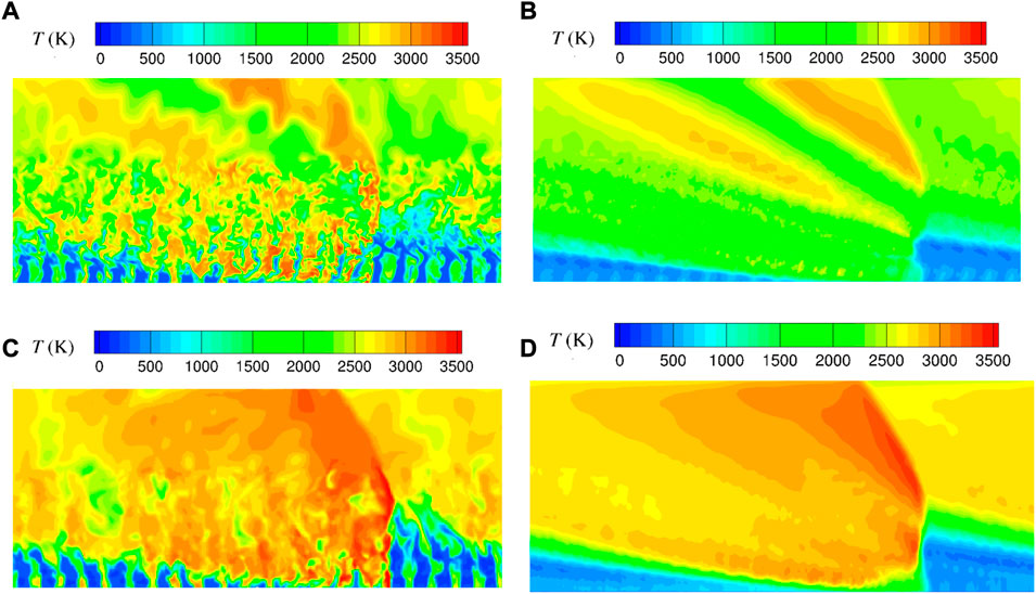
FIGURE 9. Instantaneous (A,C) and averaged (B,D) temperature fields for RD propagation on a series of SI (A,B) and ITEM (C,D) elements.
A more detailed analysis is carried out to compare the mixing performance of the two elements. A methodology has been presented in (Gaillard et al., 2017) to define a control volume (CV) in front of an RD that slides with the RD propagation, within which averaged properties in time and space can be evaluated. The three parameters determined within the CV and discussed below are YBG, the mass fraction of burnt gases, ηD, the mass of fresh mixture in stoichiometric proportions burnt by the RD with respect to the injected mass, and ηmix, the mass of stoichiometric mixture with respect to the injected mass. The injected mass corresponds to a mean temporal period of detonation propagation. Figure 10 shows the profiles of these three mixture parameters along the normalized distance to the injection wall for the ITEM element. It was found that ηD is three times greater for the ITEM element (ηD ≈ 51%) than for the SI one (ηD ≈ 17%), proving that the ITEM element allows the formation of a greater quantity of stoichiometric mixture than the SI one. With a better mixing quality, a greater quantity of fresh gases can also be consumed by deflagration between two successive RDs. Consequently, the presence of burnt gases in volume V is greater for the ITEM element (YBG ≈ 24%) than for the SI one (YBG ≈ 15%). It has been observed that the increase in the burnt gas fraction in CV causes a thickening of the fresh layer in front of the RD. Finally, ηmix is trickier to evaluate because it indicates the total amount of mixture formed in stoichiometric proportions during a RD propagation period. Only an interval can at least be given for ηmix. On the one hand, it can be assumed that the value of YBG comes from the consumption of the injected mixture by deflagration (upper limit of ηmix). On the other hand, it can be assumed that YBG represents the burnt gas from the previous RD (this is the lower limit of ηmix). With this limiting assumption, the ηmix interval is (17, 31) % for the SI element and (51, 75) % for the ITEM element, thus showing the superiority of the ITEM element.
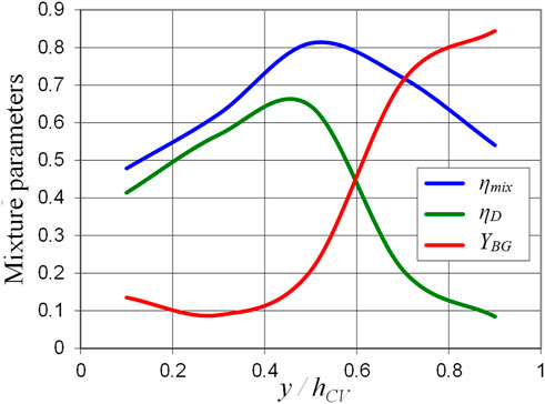
FIGURE 10. Profiles of fresh mixture parameters in front of the detonation wave for the ITEM element along the distance to the injection wall normalized by the control volume height.
As a more realistic application, half of an annular RDC fed with a stoichiometric H2/O2 mixture is calculated. The inner and outer diameters of the RDC are approximately 30 and 34 mm respectively, giving an annular gap of 4 mm, and the chamber length is 40 mm. The geometry of the injector using the ITEM element type is shown in Figure 11. For this first HPC simulation with an annular geometry, only one row of injection elements is used. The injection area ratio is close to 20% according to the previous ONERA simulations. Each injection element has a 1.7 mm diameter exit hole. There are three manifolds (one for H2 in the center and two for O2 on the inner and outer sides) which form annular ducts around the RDC axis (Figure 11A) and allow the fuel and oxidizer to be injected through the supply tubes of all the elements. Each O2 tube supplies two elements through the lateral channels (see Figure 11B). The sharing of the supply tubes between the elements was chosen because of the need to have a compact arrangement of injector elements to achieve the desired injection area ratio. As a result, the complete injector consists of 78 elements with the same number of supply tubes for O2 and H2. With the interconnected lateral channels, the injection elements form a V-shaped periodic pattern around the circumference. This compactness could be probably be increased with a higher number of injection elements, up to the technological manufacturing limit.
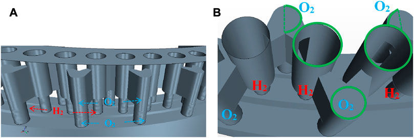
FIGURE 11. Assembly of ITEM elements as an annular injector. (A) View of the ITEM elements and their manifolds. (B) Closer view at the pre-chambers, oxygen feeding tubes and lateral channels. The green contours highlight a periodic pattern.
A LES with the Smagorinsky subgrid viscosity model is performed on a 70-million cell mesh, with 100 μm cells in the injector and near to the injector wall. As in the simulations shown in Figures 6, 11 reacting species are considered. A physical time of 1 µs takes about 500 CPU hours. A pressure sensor located at the mid radius of the RDC allows the recording of pressure signals from fully premixed to fully separate injection regimes, e.g., Figure 12. The fully premixed injection regime is simulated from 0 to 736 µs. The pressure peaks do not appear regularly, i.e., a completely stable operation is not obtained, with extinction and re-ignition phenomena. From 736 to 1,100 µs, a transition takes place from fully premixed to fully separate injection regimes at the inlet boundary of the manifolds. Then, it takes about 100 µs, from 1,100 to 1,200 µs, to reach fully separated injection conditions in the fresh mixture layer. Figure 12 also shows plots of the different regimes.
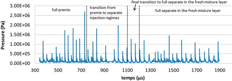
FIGURE 12. Pressure signal in the HPC simulation of an annular RDC, showing the corresponding injection regimes.
The pressure peaks are well repeated between 1,020 and 1,244 µs, indicating the stable propagation of a single RD wave, with a mean velocity of 2,694 m/s and a standard deviation of 60 m/s (here, the number of RDs is given for one-half of the chamber circumference). This first regime, i.e., the first stable propagation, is obtained during the transition phase. Between 1,244 and 1,568 µs, chaotic propagation with one to three counter-rotating waves is observed. Finally, after 1,568 µs, a single wave regime is established, with a mean velocity of 2,550 m/s and a standard deviation of 250 m/s. In conclusion, stable propagations can be obtained for both premixed and separate injection regimes. Their propagation velocities are close to each other for both the linear and annular configurations. The ITEM injector looks promising as it provides a good mixture quality under RDC conditions.
Today, many laboratory demonstrators are producing results with different fuels, injection techniques, operating conditions and RDE chamber dimensions and geometries. Combined research and technology efforts are now required to understand the fundamentals of rotating detonation engines and to develop sufficient knowledge and models to assess which performance an operational engine can achieve. The engineering effort now focuses on:
- the effect of injection configuration and conditions,
- the stable operating range and the key parameters influencing it,
- the effects of high-speed tangential flow (skin friction and heat fluxes),
- the thermal and mechanical strengths of the combustion wall (fuel-cooled structure, high-frequency mechanical shocks),
- the effect of asymmetric injection on thrust vectoring with the inclusion of a full nozzle,
- the generated environment (vibration and acoustics),
- . .
Since 2010, two test rigs at MBDA France have been able to address these issues. The first is a small-scale demonstrator designed to validate laboratory results under industrial conditions. The second is representative of a full-scale engine. Its modularity makes it possible to replace each engine component with a flight-suitable one. The final result will be a working demonstrator that can address all technological issues and ensure that the desired performance is achievable.
This demonstrator has an annular chamber (Figure 13A) with a length of 90 mm, inner and outer diameters of 80 and 100 mm, respectively, and an outer wall thickness of 25 mm (Le Naour, et al., 2011). The material is an alloy consisting mainly of copper and zirconium. There is no cooling system, so heating limits the test durations to a few seconds. We set the maximum duration to 5s. The center body of the chamber can be changed to study its influence on engine performance.
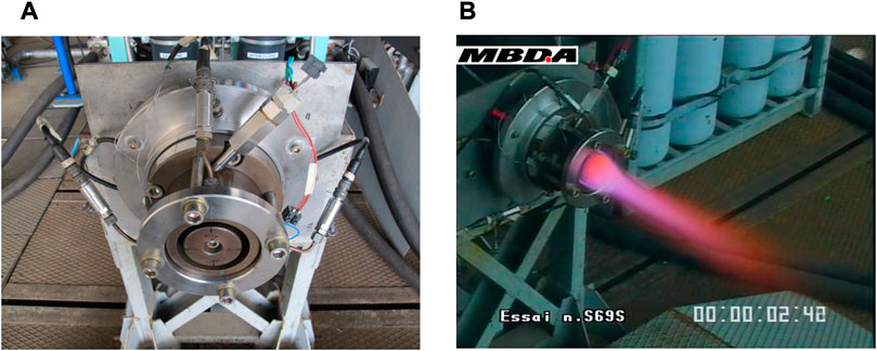
FIGURE 13. The small scale RDE demonstrator and its ignition device (A), and its operation with a H2/O2 mixture (B).
The fuel is either hydrogen or a mixture of hydrogen and methane. In the rocket mode operation (Figure 13B), the fuel and the oxidizer are injected separately in the axial direction through an injection plate. The injection device can be replaced and modified to test different configurations. The injection manifolds are divided into four sectors to vary the local mass flow rate and investigate the thrust vectoring effect.
The fuel and oxidizer tanks can withstand a maximum pressure of 80 bar. They have the same volume of 20 dm3. The supply pressures of the fuel and the oxidizer monitor the equivalence ratio of the injected mixture. The equivalence ratio and specific flow rate vary as the receivers empty, so a large number of operating points can be collected.
Ignition is performed tangentially to the annular chamber through an explosive wire device delivering energy of approximately 10 J.
The thrust is obtained from three strain gauges positioned between the engine and the structure of the bench (Figure 14A) shows an example of a thrust measurement for a mixture of hydrogen and oxygen. Here the measured thrust is 54.7 N on the ground, equivalent to 338.5 N in vacuum. The corresponding specific impulse is 341.7s. These results agree well with those calculated for these injection conditions (Le Naour et al., 2011). This bench is modular and easy to implement, so many injection configurations, materials and measurements of thermal fluxes, for example, can be carried out quickly.
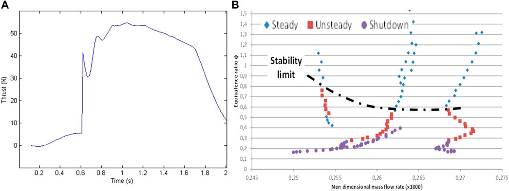
FIGURE 14. (A): Small scale demonstrator: filtered signal of the total thrust. (B): Large-scale demonstrator: stability limit in hydrogen/air injection conditions.
This large-scale demonstrator operates in air-breathing mode. Its purpose is to demonstrate the feasibility of integrating an RDE into a turbojet engine and show the expected efficiency gains over a conventional constant-pressure combustor. This demonstrator is an element of a test bench that addresses the key issues for developing such an engine, namely the.
- stable operating range for a given fuel,
- thermo-mechanical conditions generated at the chamber wall,
- validation of the fuel-cooled structures,
- vibration conditions generated by the whole system,
- integration of a compressor and a turbine.
This requires the supply of fluids to the engine under precise and representative temperature and pressure conditions, which MBDA France’s ramjet facility in Bourges can achieve (Figure 15A). The facility allows long-duration tests and provides air mass flow rates of up to 60 kg/s under the maximum conditions of 15 bar and 750 K for the total pressure and temperature. The air/O2/H2 heaters increase the air temperature, and the hydrogen combustion achieves the required temperature. A supplemental oxygen flow provides an exhaust mixture with an oxygen molar fraction of 23%.
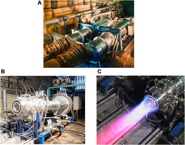
FIGURE 15. (A) The ramjet facility of MBDA France in Bourges. (B,C) The large-scale RDE demonstrator connected to the ramjet facility (A), and its operation with hot air and gaseous hydrogen.
O-ring joints ensure the connection between the facility and the RDE. The heated air from the burner passes through a first annular sonic throat, which makes it possible to maintain constant pressure in the air heater. A constant annular section then stabilizes the flow before its injection into the chamber. A second sonic throat, actually the air injection device of the RDE, maintains the injection pressure to a maximum value of 8 bar.
The current version of the demonstrator (Figure 15B) is an annular chamber made of stainless steel and acts as a heat sink. The maximum duration of the tests is approximately 10 seconds. The outer and inner diameters of the chamber are 330 and 280 mm, respectively. The air is injected along the engine axis, and the fuel is injected perpendicular to the airflow through calibrated holes distributed around the outer and inner walls of the engine.
Ignition is achieved using a pre-detonation tube tangential to the RDE annular channel, similar to that used on the small-scale demonstrator. A spark plug ignites a flame in the fresh reactive mixture fed into the tube. Inspired by the Shchelkin spiral technique, obstacles in the tube accelerate the flame to quasi-sonic speeds. The transition from deflagration to detonation occurs if the tube is long enough, depending on the mixture conditions.
Preliminary tests considered a mixture of gaseous hydrogen and hot air (Figure 15C). The objectives were 1) to verify the correct operation of the test-line and engine-demonstrator assembly and 2) to define a method for analyzing measured data and thus determining the detonation regime set in the chamber. A parametric study of the operating conditions was carried out by varying the injected mass flow rate, the total temperature at the engine inlet and the injected equivalence ratio. The results determined the stability range of the engine with hydrogen and air injection (Figure 14B). The data seem to show that, for a given geometry, the higher the mass flow and total temperature, the more stable the detonation regime (Le Naour, et al., 2017). Other key issues to be addressed are the quality of the mixing and the homogeneity of the fuel/air mixture to approach as closely as possible the theoretical performance.
A sufficiently high level of technological readiness is a necessary starting point for defining the dimensions and technologies of RDE chambers, as for more classical propulsion devices. That means that the constraints of the assigned mission must be considered first, and only then the limited conclusions from laboratory demonstrators or numerical simulations. These are necessary for proofs of concept at a lower cost but can provide only partial qualitative information on the difficulties to be overcome, such as the interplay of all the phenomena involved in real situations and the thermal and mechanical properties of the materials.
All authors listed have made a substantial, direct, and intellectual contribution to the work and approved it for publication.
ONERA study was funded by the General Scientific Directorate of ONERA.
The authors are grateful to R. Zitoun (University of Poitiers & CNRS-Pprime) for her advice and suggestions. Drs TG and DD thank the ONERA IT team for having attributed high CPU time as part of an HPC simulation of RD propagation to test the last upgrade of ONERA’s cluster.
The authors declare that the research was conducted in the absence of any commercial or financial relationships that could be construed as a potential conflict of interest.
All claims expressed in this article are solely those of the authors and do not necessarily represent those of their affiliated organizations, or those of the publisher, the editors and the reviewers. Any product that may be evaluated in this article, or claim that may be made by its manufacturer, is not guaranteed or endorsed by the publisher.
Anand, V., George, A. C. S., and Gutmark, E. (2016). “Hollow rotating detonation combustor,” in 54th AIAA Aerospace Sciences Meeting, Reston, Virginia, 1–15. s.n.
Andrus, I. Q., King, P., Fotia, M., Schauer, F., and Hoke, J. (2015). “Experimental analogue of a pre-mixed rotating detonation engine in plane flow,” in 53rd AIAA Aerospace Sciences Meeting, Kissimmee, Florida, 1105. s.n.
Andrus, I. Q., King, P. I., Polanka, M. D., Schauer, F. R., and Hoke, J. L. (2017a). Design of a premixed fuel-oxidizer system to arrest flashback in a rotating detonation engine. J. Propuls. Power 33 (5), 1063–1073. doi:10.2514/1.b36259
Andrus, I. Q., Polanka, M. D., King, P. I., Schauer, F. R., and Hoke, J. L. (2017b). Experimentation of premixed rotating detonation engine using variable slot feed plenum. J. Propuls. Power 33 (6), 1448–1458. doi:10.2514/1.b36261
Athmanathan, V., Braun, J., Ayers, Z. M., Fugger, C. A., Webb, A. M., Slipchenko, M. N., et al. (2022). On the effects of reactant stratification and wall curvature in non-premixed rotating detonation combustors. Combust. Flame 240, 112013. doi:10.1016/j.combustflame.2022.112013
Austin, J. M., Pintgen, F., and Shepherd, J. E. (2005). Reaction zones in highly unstable detonations. Proc. Combust. Inst. 30 (2), 1849–1857. doi:10.1016/j.proci.2004.08.157
Bykovskii, F., and Vedernikov, E. (1996). Continuous detonation combustion of an annular gas-mixture layer. Combust. Explos. Shock Waves 32 (5), 489–491. doi:10.1007/bf01998570
Bykovskii, F. A., Zhdan, S. A., and Vedernikov, E. F. (2008). Continuous spin detonation of hydrogen-oxygen mixtures. 1. Annular cylindrical combustors. Combust. Explos. Shock Waves 44 (2), 150–162. doi:10.1007/s10573-008-0021-1
Clavin, P., and Searby, G. (2016). Combustion waves and fronts in flows: Flames, shocks, detonations, ablation fronts and explosion of stars. Cambridge University Press. s.l.
Crane, J., Lipkowicz, J. T., Shi, X., Wlokas, I., and Kempf, A. M. (2022). Three-dimensional detonation structure and its response to confinement. Proc. Combust. Inst. doi:10.1016/j.proci.2022.10.019
Davidenko, D. M., Gökalp, I., and Kudryavtsev, A. N. (2007). Numerical simulation of the continuous rotating hydrogen-oxygen detonation with a detailed chemical mechanism. Moscow, Russia. s.n.
Denisov, Y. N., and Troshin, Y. K. (1959). Pulsating and spinning detonation of gaseous mixtures in tubes. Dokl. Akad. Nauk. SSSR 125 (1), 110–113.
Denisov, Y. N., and Troshin, Y. K. (1960). Structure of gaseous detonation in tubes. Sov. Phys. Tech. Phys. 5 (4), 419–431.
Desbordes, D., and Presles, H. N. (2012). “Multi-scaled cellular detonation,” in Shock Waves Science and Technology Library (Berlin, Heidelberg: Springer), 281–338.
Duvall, J., Chacon, F., Harvey, C., and Gamba, M. (2018). “Study of the effects of various injection geometries on the operation of a rotating detonation engine,” in AIAA Aerospace Sciences Meeting. s.l.
Edwards, D., Fearnley, P., Thomas, G., and Nettleton, M. (2018). Shocks and detonation in channels with 90° bends, Talence, France, 431–435. s.n.
Eude, Y., Davidenko, D., Falempin, F., and Gökalp, I. (2011). “Use of the adaptive mesh refinement for 3D simulations of a CDWRE (continuous detonation wave rocket engine),” in 17th AIAA International Space Planes and Hypersonic Systems and Technologies Conference, San Francisco, California, 2236.
Frederick, M. D., Gejji, R. M., Shepherd, J. E., and Slabaugh, C. D. (2022). Time-resolved imaging of the cellular structure of methane and natural gas detonations. Shock Waves 32, 337–351. doi:10.1007/s00193-022-01080-8
Frolov, S., Aksenov, V., Ivanov, V., and Shamshin, I. (2015). Large-scale hydrogen-air continuous detonation combustor. Int. J. Hydrogen Energy 40 (3), 1616–1623. doi:10.1016/j.ijhydene.2014.11.112
Gaillard, T., Davidenko, D., and Dupoirieux, F. (2015). Numerical optimisation in non reacting conditions of the injector geometry for a continuous detonation wave rocket engine. Acta Astronaut. 111, 334–344. doi:10.1016/j.actaastro.2015.02.006
Gaillard, T., Davidenko, D., and Dupoirieux, F. (2017). Numerical simulation of a rotating detonation with a realistic injector designed for separate supply of gaseous hydrogen and oxygen. Acta Astronaut. 141, 64–78. doi:10.1016/j.actaastro.2017.09.011
Gaillard, T., Davidenko, D., and Dupoirieux, F. (2019). Numerical investigation of an unsteady injection adapted to the continuous detonation wave rocket engine operation. Prog. Propuls. Phys. 11, 347–370.
Hanana, M., Lefebvre, M. H., and Van Tiggelen, P. J. (1998). “On rectangular and diagonal three-dimensional structures of detonation waves,” in Gaseous and heterogeneous detonations: Science to applications (St Petersburg: ENAS Publishers), 121–129.
Hansmetzger, S., Zitoun, R., and Vidal, P. (2018). A study of continuous rotation modes of detonation in an annular chamber with constant or increasing section. Shock Waves 28, 1065–1078. doi:10.1007/s00193-018-0846-9
Hayashi, A. K., Kimura, Y., Yamada, T., Yamada, E., Kindracki, J., Dzieminska, R., et al. (2009). “Sensitivity analysis of rotating detonation engine with a detailed reaction model,” in 47th AIAA Aerospace Sciences Meeting including The New Horizons Forum and Aerospace Exposition, Orlando, Florida. s.n.
Hishida, M., Fujiwara, T., and Wolanski, P. (2009). Fundamentals of rotating detonations. Shock waves 19 (1), 1–10. doi:10.1007/s00193-008-0178-2
Ishihara, K., Nishimura, J., Goto, K., Nakagami, S., Matsuoka, K., Kasahara, J., et al. (2017). “Study on a long-time operation towards rotating detonation rocket engine flight demonstration,” in 55th AIAA Aerospace Sciences Meeting, Grapevine, Texas, 1062. s.n.
Jackson, S. I., and Short, M. (2013). The influence of the cellular instability on lead shock evolution in weakly unstable detonation. Combust. Flame 160 (10), 2260–2274. doi:10.1016/j.combustflame.2013.04.028
Kawalec, M. (2021). The world’s first launch of a rocket powered by a detonation engine. Lukasiewicz Institute of Aviation. [En ligne]. Available at: https://ilot.lukasiewicz.gov.pl/en/the-worlds-first-launch-of-a-rocket-powered-by-a-detonation-engine/.
Keisuke, G., and al, e. (2022). Flight demonstration of detonation engine system using sounding rocket S-520-31: Performance of rotating detonation engine. San Diego: American Institute of Aeronautics and Astronautics Inc, AIAA.
Kindracki, J., Wolański, P., and Gut, Z. (2011). Experimental research on the rotating detonation in gaseous fuels–oxygen mixtures. Shock waves 21, 75–84. doi:10.1007/s00193-011-0298-y
Kobiera, A., Folusiak, M., Swiderski, K., Kindracki, J., and Wolanski, P. (2009). “Three-dimensional modeling of the rotating detonation engine,” in 22nd ICDERS, Minsk, Belarus, July 27–31.
Kudo, Y., Nagura, Y., Kasahara, J., Sasamoto, Y., and Matsuo, A. (2011). Oblique detonation waves stabilized in rectangular-cross-section bent tubes. Proc. Combust. Inst. 33 (2), 2319–2326. doi:10.1016/j.proci.2010.08.008
Le Naour, B., Falempin, F., and Miquel, F. (2011). “Recent experimental results obtained on continuous detonation wave engine,” in 17th AIAA International Space Planes and Hypersonic Systems and Technologies Conference, San Francisco, California, 2235.
Le Naour, B., Falempin, F., and Coulon, K. (2017). “MBDA R&T effort regarding continuous wave engine for propulsion - status in 2016,” in 21st AIAA International Space Planes and Hypersonics Technologies Conference, Xiamen, China.
Li, J. M., Chang, P. H., Li, L., Yang, Y., Teo, C. J., Khoo, B. C., et al. (2018). “Investigation of injection strategy for liquid-fuel rotating detonation engine,” in AIAA aerospace sciences meeting. s.l.
Libouton, J. C., Jacques, A., and Van Tiggelen, P. J. (1981). “Cinétique, structure et entretien des ondes de détonation,” in Actes du Colloque International Berthelot-Vieille-Mallard-Le Chatelier (2), Bordeaux, 649–660.
Lin, W., Zhou, J., Liu, S., and Lin, Z. (2015). An experimental study on CH4/O2 continuously rotating detonation wave in a hollow combustion chamber. Exp. Therm. Fluid Sci. 62, 122–130. doi:10.1016/j.expthermflusci.2014.11.017
Ma, J. Z., Zhang, S., Luan, M., and Wang, J. (2019). Experimental investigation on delay time phenomenon in rotating detonation engine. Aerosp. Sci. Technol. 88, 395–404. doi:10.1016/j.ast.2019.01.040
Melguizo-Gavilanes, J., Rodriguez, V., Vidal, P., and Zitoun, R. (2021). Dynamics of detonation transmission and propagation in a curved chamber: A numerical and experimental analysis. Combust. Flame 223, 460–473. doi:10.1016/j.combustflame.2020.09.032
Monnier, V., Rodriguez, V., Vidal, P., and Zitoun, R. (2022). An analysis of three-dimensional patterns of experimental detonation cells. Combust. Flame 245, 112310. doi:10.1016/j.combustflame.2022.112310
Monnier, V., Vidal, P., Rodriguez, V., and Zitoun, R. (2023). “From graph theory and geometric probabilities to a representative width for three-dimensional detonation cells,” in Submission #8 to the 30th ICDERS. Available at arXiv and HAL.
Nakayama, H., Moriya, T., Kasahara, J., Matsuo, A., Sasamoto, Y., and Funaki, I. (2012). Stable detonation wave propagation in rectangular-cross-section curved channels. Combust. Flame 159 (2), 859–869. doi:10.1016/j.combustflame.2011.07.022
Nakayama, H., Kasahara, J., Matsuo, A., and Funaki, I. (2013). Front shock behavior of stable curved detonation waves in rectangular-cross-section curved channel. Proc. Combust. Inst. 34 (2), 1936–1947.
Nicholls, J., Cullen, R., and Ragland, K. (1966). Feasibility studies of a rotating detonation wave rocket motor. J. Spacecr. Rockets 3, 893–898. doi:10.2514/3.28557
Pal, P., Demir, S., and Som, S. (2023). Numerical analysis of combustion dynamics in a full-scale rotating detonation rocket engine using large eddy simulations. J. Energy Resour. Technol. 145 (2).
Pintgen, F. P., and Shepherd, J. E. (2003). “Simultaneous soot foil and PLIF imaging of propagating detonations,”. Paper 119 in Proceeding of the 19th International Colloquium on the Dynamics of Explosions and Reactive Systems. s.l.
Pintgen, F. P., Eckett, C. A., Austin, J. M., and Shepherd, J. E. (2003). Direct observations of reaction zone structure in propagating detonations. Combust. Flame 133 (4), 211–229. doi:10.1016/s0010-2180(02)00458-3
Prakash, S., Raman, V., Lietz, C. F., Hargus, W. A., and Schumaker, S. A. (2021). Numerical simulation of a methane-oxygen rotating detonation rocket engine. Proc. Combust. Inst. 38 (3), 3777–3786. doi:10.1016/j.proci.2020.06.288
Radulescu, M. I., Sharpe, G. J., and Bradley, D. (2013). “A universal parameter quantifying explosion hazards, detonability and hot spot formation: Number,” in Proceedings of the 7th International Seminar on Fire and Explosion Hazards (Research Publishing).
Rankin, B. A., Richardson, D. R., Caswell, A. W., Naples, A. G., Hoke, J. L., and Schauer, F. R. (2017). Chemiluminescence imaging of an optically accessible non-premixed rotating detonation engine. Combust. Flame 176, 12–22. doi:10.1016/j.combustflame.2016.09.020
Refloch, A., Courbet, B., Murrone, A., Villedieu, P., Laurent, C., Gilbank, P., et al. (2011). CEDRE software. Aerosp. Lab J. 2, 1–10.
Rodriguez, V., Jourdain, C., Vidal, P., and Zitoun, R. (2019). An experimental evidence of steadily-rotating overdriven detonation. Combust. Flame 202, 132–142. doi:10.1016/j.combustflame.2019.01.016
Sato, T., Chacon, F., Gamba, M., and Raman, V. (2021). Mass flow rate effect on a rotating detonation combustor with an axial air injection. Shock Waves 31 (7), 741–751. doi:10.1007/s00193-020-00984-7
Schwer, D., and Kailasanath, K. (2010). “Numerical investigation of rotating detonation engines,” in 46th AIAA/ASME/SAE/ASEE Joint Propulsion Conference & Exhibit, Nashville, Tennessee, 6880. s.n.
Schwer, D. A., Johnson, R. F., Kercher, A., Kessler, D. A., and Corrigan, A. T. (2020). “Numerical investigation of centerbody-less rotating detonation combustors,” in AIAA Scitech 2020 Forum, 2158.
Short, M., and Sharpe, G. (2003). Pulsating instability of detonations with a two-step chain-branching reaction model: Theory and numerics. Combust. Theory Model. 7 (2), 401–416. doi:10.1088/1364-7830/7/2/311
Short, M., Quirk, J., Chiquete, C., and Meyer, C. (2018). Detonation propagation in a circular arc: Reactive burn modelling. J. Fluid Mech. 835, 970–998. doi:10.1017/jfm.2017.751
Short, M., Chiquete, C., and Quirk, J. (2019). Propagation of a stable gaseous detonation in a circular arc configuration. Proc. Combust. Inst. 37 (3), 3593–3600. doi:10.1016/j.proci.2018.06.212
Stoddard, W., St. George, A. C., Driscoll, R. B., and Gutmark, E. J. (2014). “Computational analysis of existing and altered rotating detonation engine inlet designs,” in 50th AIAA/ASME/SAE/ASEE Joint Propulsion Conference, Cleveland, Ohio, 3668. s.n.
Sun, J., Zhou, J., Liu, S., Lin, Z., and Lin, W. (2019). Effects of air injection throat width on a non-premixed rotating detonation engine. Acta Astronaut. 159, 189–198. doi:10.1016/j.actaastro.2019.03.067
Tang, X., Wang, J., and Shao, Y. (2015). Three-dimensional numerical investigations of the rotating detonation engine with a hollow combustor. Combust. Flame 162, 997–1008. doi:10.1016/j.combustflame.2014.09.023
Thomas, G., and Williams, R. (2002). Detonation interaction with wedges and bends. Shock Waves 11 (6), 481–492. doi:10.1007/s001930200133
Van Tiggelen, P. J., and Libouton, J. C. (1989). Evolution des variables chimiques et physiques à l'intérieur d'une maille de détonation. Ann. Phys. 14 (6), 649–660. doi:10.1051/anphys:01989001406064900
Weiss, S., Bohon, M. D., Paschereit, C. O., and Gutmark, E. J. (2020). Computational study of reactants mixing in a rotating detonation combustor using compressible RANS. Flow, Turbul. Combust. 105 (1), 267–295. doi:10.1007/s10494-019-00097-x
Wen, H., Xie, Q., and Wang, B. (2019). Propagation behaviors of rotating detonation in an obround combustor. Combust. Flame 210, 389–398. doi:10.1016/j.combustflame.2019.09.008
Wolanski, P. (2013). Detonative propulsion. Proc. Combust. Inst. 34 (1), 125–158. doi:10.1016/j.proci.2012.10.005
Xu, G., Wu, Y., Xiao, Q., Ding, C., Xia, Y., Li, Q., et al. (2022). Characterization of wave modes in a kerosene-fueled rotating detonation combustor with varied injection area ratios. Appl. Therm. Eng. 212, 118607. doi:10.1016/j.applthermaleng.2022.118607
Yamada, T., Hayashi, K., Tsuboi, N., Yamada, E., Tangirala, V., and Fujiwara, T. (2010). “Numerical analysis of threshold of limit detonation in rotating detonation engine,” in 48th AIAA Aerospace Sciences Meeting Including the New Horizons Forum and Aerospace Exposition, Orlando, Florida, 153. s.n.
Zhang, H., Liu, W., and Liu, S. (2017). Experimental investigations on H2 − air rotating detonation wave in the hollow chamber with laval nozzle. Int. J. Hydrogen Energy 42 (5), 3363–3370. doi:10.1016/j.ijhydene.2016.12.038
Zhao, H., Lee, J. H. L. J., and Zhang, Y. (2016). Quantitative comparison of cellular patterns of stable and unstable mixtures. Shock Waves 26 (10), 621–633. doi:10.1007/s00193-016-0673-9
Zhdan, S. A., Bykovskii, F. A., and Vedernikov, E. F. (2007). Mathematical modeling of a rotating detonation wave in a hydrogen-oxygen mixture. Combust. Explos. shock waves 43 (4), 449–459. doi:10.1007/s10573-007-0061-y
Zheng, Y., Wang, C., Xiao, B., Liu, Y., and Cai, J. (2020). Numerical simulation of radial-stratified rotating detonation flow field structures with different injection patterns. Int. J. Hydrogen Energy 45 (6), 32619–32631. doi:10.1016/j.ijhydene.2020.09.005
Keywords: rotating detonation, cellular structure, injector design, mixing quality, numerical simulation, large-scale demonstrator
Citation: Le Naour B, Davidenko D, Gaillard T and Vidal P (2023) Rotating detonation combustors for propulsion: Some fundamental, numerical and experimental aspects. Front. Aerosp. Eng. 2:1152429. doi: 10.3389/fpace.2023.1152429
Received: 27 January 2023; Accepted: 17 March 2023;
Published: 30 March 2023.
Edited by:
Simone Salvadori, Polytechnic University of Turin, ItalyReviewed by:
Jinglei Xu, Nanjing University of Aeronautics and Astronautics, ChinaCopyright © 2023 Le Naour, Davidenko, Gaillard and Vidal. This is an open-access article distributed under the terms of the Creative Commons Attribution License (CC BY). The use, distribution or reproduction in other forums is permitted, provided the original author(s) and the copyright owner(s) are credited and that the original publication in this journal is cited, in accordance with accepted academic practice. No use, distribution or reproduction is permitted which does not comply with these terms.
*Correspondence: Pierre Vidal, cGllcnJlLnZpZGFsQGVuc21hLmZy
Disclaimer: All claims expressed in this article are solely those of the authors and do not necessarily represent those of their affiliated organizations, or those of the publisher, the editors and the reviewers. Any product that may be evaluated in this article or claim that may be made by its manufacturer is not guaranteed or endorsed by the publisher.
Research integrity at Frontiers

Learn more about the work of our research integrity team to safeguard the quality of each article we publish.