- 1Department of Aerospace Engineering, Institute of Fluid Science, Tohoku University, Sendai, Japan
- 2Institute of Fluid Science, Tohoku University, Sendai, Japan
A conceptual design optimization problem for commercial transport airplanes with turboelectric propulsion, with a reasonable fidelity and comprehensiveness suitable for industrial purposes, is formulated, in order to allow for proper assessment of the benefits of turboelectric propulsion. As a sample problem, we carry out conceptual design optimization of a turboelectric propulsion airplane concept in a conventional tube-and-wing configuration with a turbofan and an associated electric fan on each (i.e., left and right) wing, varying the performance of the turboelectric propulsion devices. The results indicate that proper assessment of the benefits of the turboelectric propulsion can be carried out using the formulated optimization problem. The findings from the sample problem, including notable benefits of the turboelectric propulsion and the performance crossover point where the fuel efficiency of an airplane with conventional propulsion and that of an airplane with turboelectric propulsion cross over, are also presented.
1 Introduction
Airplane conceptual design, such as conceptual design of commercial transport airplanes, is a complex and time-consuming task, as many design parameters need to be optimized within numerous contradicting constraints where many factors are inter-related (Roskam, 1985; Raymer, 1989; Jenkinson et al., 1999). For example, a higher bypass ratio (BPR) of a turbofan (TF) improves the propulsive efficiency, providing better fuel efficiency. However, it also increases the engine diameter, which requires a longer main landing gear to retain a proper roll margin and prevent the airframe from contacting the ground in maneuvers during takeoffs and landings. This longer—and, hence, heavier—main landing gear could cancel out the fuel efficiency improvement provided by the higher BPR.
Various preliminary conceptual design optimization problems have been formulated for commercial transport airplanes, focusing on fuel economy with a single objective (Roth and Crossley, 1998; Perez et al., 2000) and with multiple objectives Perez and Behdinan (2002), then, focusing on environmental sustainability (Antonie and Kroo, 2005; Henderson et al., 2012). However, conceptual design optimization of commercial transport airplanes for industrial purposes, such as those performed in airplane manufacturing companies as a day-to-day business, requires a reasonable fidelity and comprehensiveness, because failing to select an appropriate airplane concept could be fatal to the airplane development program. The fidelity and comprehensiveness are also required because the results of the conceptual design constitute a baseline of the system design requirements used in subsequent design phases. For this, a conceptual design optimization problem, with a reasonable fidelity and comprehensiveness suitable for industrial purposes, has been formulated by the authors Takami and Obayashi (2022b) for commercial transport airplanes with conventional propulsion.
Owing to the recent progress in power electronics technologies, the performance of power electronics devices has significantly improved. Based on such improvement, propulsion systems with these devices—referred to as turboelectric propulsion (TEP) systems—have become the object of intensive research, with the aim of improving fuel efficiency of commercial transport airplanes.
One benefit of TEP systems is that the power generated by the turbine can be relocated relatively freely: not only to the fan mechanically connected to the turbine, but also to remotely located but electrically connected electric fans, referred to as the remote fans (RFs) in this study. This feature of TEP systems allows for a flexible arrangement of the propulsion system in an airplane. The potential of TEP was intensively investigated in NASA’s N+3 aircraft concept development Greitzer et al. (2010). Various TEP airplane concepts have ever been proposed and studied, applying this feature to various airplane configurations: innovative blended wing–body configurations (Felder et al., 2011; Kim et al., 2013), truss-braced wing configurations Bradley and Droney (2012), and conventional tube-and-wing configurations with RF(s) in the wing (Gibson et al., 2010; Schiltgen et al., 2012; Schiltgen et al., 2016) or at the aft end of the fuselage (Welstead and Felder, 2016); Jansen et al., 2016; 2017b). NASA’s research on TEP for large subsonic transports was well overviewed by Jansen et al. (2017a). Comprehensive reviews on technological issues regarding TEP were well summarized in National Academies (2016) and Brelje and Martins (2019).
From the perspective of airplane configuration design, TEP has various potentials. For example, the main landing gear, which retains the proper roll margin of the airplane for safe takeoffs and landings, could be made shorter—and, hence, lighter—by relocating a part of the power generated by the turbine to the RF and shrinking the diameter of the TF. The potentials of TEP, however, have not been investigated well enough from the perspective of industrial purposes, because conceptual design optimization problems for commercial transport airplanes with TEP have not yet been formulated with a reasonable fidelity and comprehensiveness to allow for the proper assessment of the benefits of TEP.
In this study, a conceptual design optimization problem for commercial transport airplanes with TEP, with a reasonable fidelity and comprehensiveness suitable for industrial purposes, is formulated, in order to allow for the proper assessment of the benefits of TEP, extending upon the conceptual design optimization problem formulated by Takami and Obayashi (2022b) for commercial transport airplanes with conventional propulsion. The scope of airplane configuration is limited to the conventional tube-and-wing configuration with a low wing, tail surfaces, and wing-mounted engines and main landing gear. As a sample problem, conceptual design optimization of a TEP airplane concept in a tube-and-wing configuration with a TF and an associated RF on each (left and right) wing was performed, varying the performance of the TEP devices.
The remainder of this paper is structured as follows. The TEP system is modeled in Section 2. The optimization problem is formulated in Section 3. The sample problem is defined and its optimization results are discussed in Section 4. Finally, directions for future research are presented in Section 5.
2 TEP system modeling
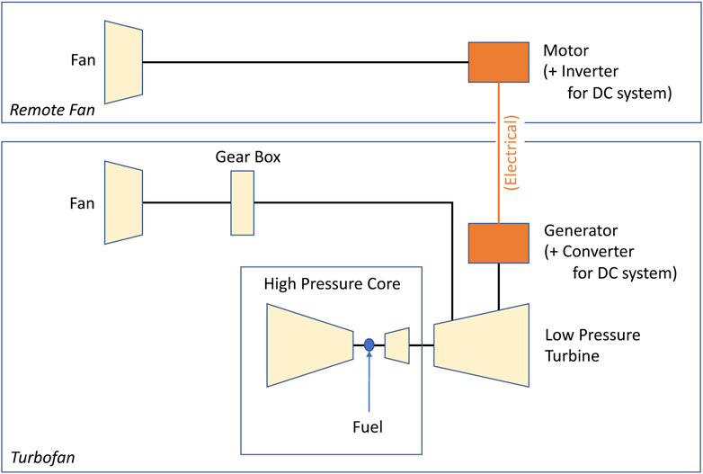
The TEP system model considered in this study is shown in Figure 1. A part of the power generated by the low-pressure turbine (LPT) is supplied to the TF fan mechanically connected to the LPT. Between the LPT and its fan, a gear box may be inserted to allow for independent optimal speeds of both the fan and the LPT (i.e., a geared TF). The rest of the power generated by the LPT is supplied to the RF electrically connected to the LPT, wherein the LPT drives a generator and its electric output is transmitted via electric wires to the motor of the RF. This TEP architecture is often called as the “partial” TEP. Refer to National Academies (2016) for the classification of electric propulsion architectures.
There are two types of electrical system for the TEP: Alternating current (AC) system Sadey et al. (2016) and direct current (DC) system Vratny et al. (2017). For an AC system, the power generated by the LPT is converted to electric power by a generator mechanically connected to the LPT. The electric power, normally in a three-phase AC, is directly conveyed to an electric motor, often called an induction motor, of the RF. The speed of the induction motor is determined solely by that of the generator. For a DC system, the electric power generated by the generator is converted to a DC by the converter immediately after the generator, conveyed to the inverter immediately before the motor of the RF, and inverted to an appropriate AC for the motor speed. This allows for an independent RF motor speed from the LPT speed, which facilitates optimal operations of both RF and TF under various flight conditions.
The model shown in Figure 1 covers both types (AC and DC) of the TEP electrical system and is suitable for the formulation of conceptual design optimization problem for commercial transport airplanes using TEP.
3 Formulation
In this study, the scope of airplane configuration was limited to the conventional tube-and-wing configuration with a low wing, tail surfaces, and wing-mounted engines and main landing gear. For the TEP airplane concepts, an RF was additionally installed outboard of the TF on each (left and right) wing. This scope is considered to be a good starting point to formulate conceptual design optimization problems for more complex commercial transport airplane concepts using TEP, such as those with TEP at the aft end of the fuselage (to be discussed in Section 5).
Selecting appropriate design parameters, constraints, and objectives is a key for a successful formulation of design optimization problem. In this study, the design parameters, constraints, and objectives, selected in the formulation of conceptual design optimization problem for commercial transport airplanes with conventional propulsion proposed by the authors Takami and Obayashi (2022b), were used as the baseline in formulating the conceptual design optimization problem for commercial transport airplanes with TEP, aiming to achieve a reasonable fidelity and comprehensiveness suitable for industrial purposes.
Details of the selection of the design parameters, constraints, and objectives, used as the baseline for this formulation, are elaborated in Takami and Obayashi (2022b).
3.1 Design parameters
In formulating the conceptual design optimization problem for commercial transport airplanes with TEP, two design parameters were added to the design parameters selected for commercial transport airplanes with conventional propulsion in Takami and Obayashi (2022b), as follows:
1. The mass flow fraction of the RF is the ratio of the RF mass flow to the overall bypass mass flow (the TF bypass mass flow plus the RF mass flow), which affects the thrust balance between the TF and RF fans. Coupled with the BPR, it also affects the diameters of the TF and RF. In conventional propulsion, the RF mass flow fraction is equal to zero (= 0), as there is no RF mass flow.
2. The spanwise location of the RF is the fraction between the spanwise location of the TF and the wing tip, which affects the stability and control characteristics of the airplane, such as the lateral-directional oscillation (Dutch roll) characteristics, roll performance, and controllability in critical engine inoperative conditions on the ground and in the air.
In this formulation, the definition of the BPR, which is the ratio of the bypass mass flow to the core mass flow Saravanamuttoo et al. (2009), is extended such that the bypass mass flow includes the RF mass flow in addition to the TF bypass mass flow. The fan pressure ratio (FPR) of the RF could be an independent design parameter; however, the FPR of the RF was assumed to be equal to that of the TF in this formulation for simplicity.
The design parameters selected in this formulation for the TEP airplanes are summarized in Table 1. A total of 21 design parameters were selected.
The upper and lower bounds of the design parameters to be used in the sample problem (see Section 4) are also listed in Table 1, which were determined from statistical analyses of existing commercial transport airplanes, based on public data (Airbus, 2022; Boeing, 2022). In the sample problem, a fixed value was set for the turbine inlet temperature to reduce the number of design parameters.
3.2 Constraints
In formulating the conceptual design optimization problem for commercial transport airplanes with TEP, one constraint was added to the constraints selected for commercial transport airplanes with conventional propulsion in Takami and Obayashi (2022b), as follows:
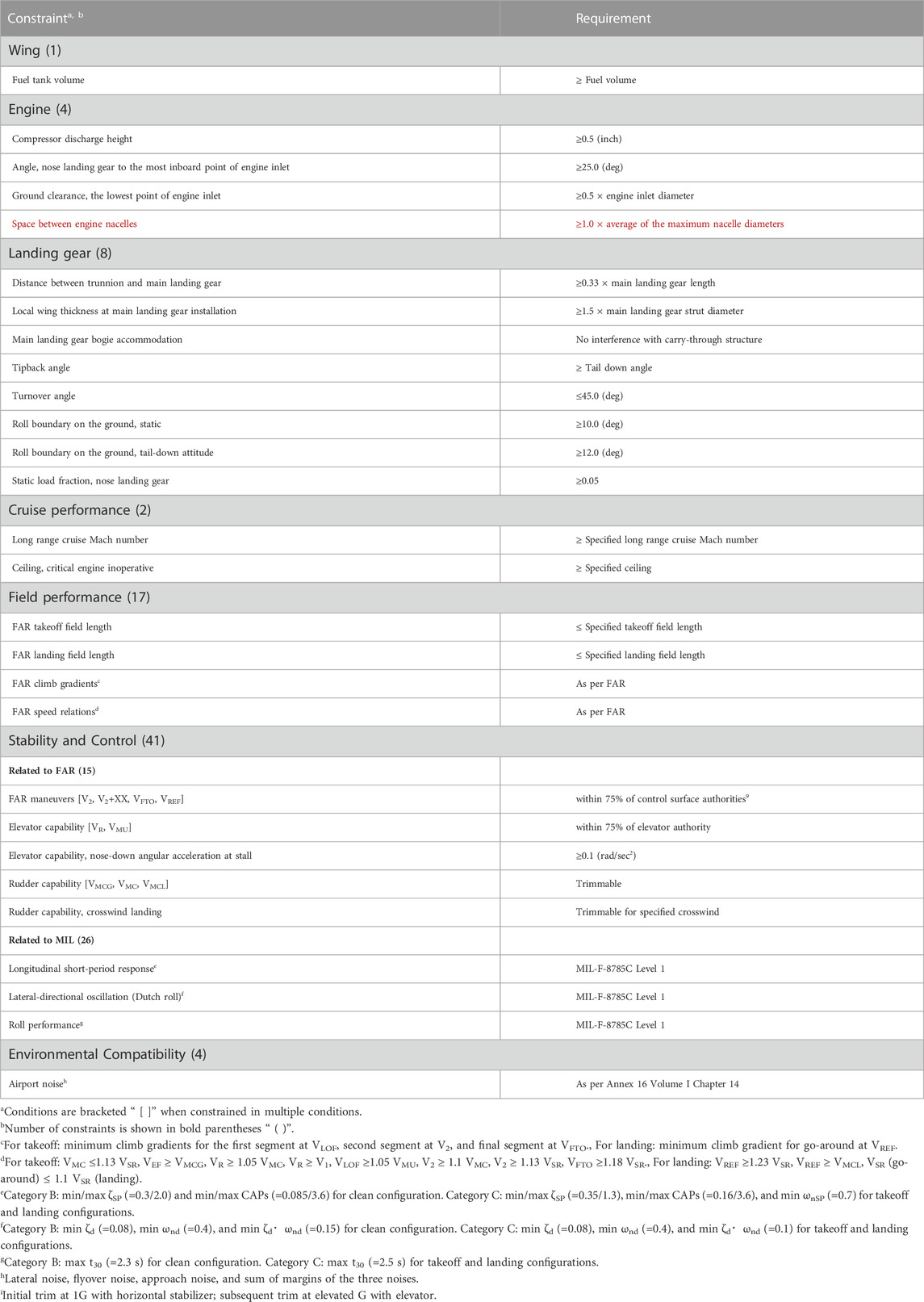
1. A reasonable space is required between the engine nacelles next to each other (in this study, the TF and RF nacelles), in order to prevent unfavorable aerodynamic interference between the two nacelles. The minimum spacing was determined from statistical analyses on the geometry of existing commercial transport airplanes, based on public data (Airbus, 2022; Boeing, 2022).
The constraints selected in this formulation are summarized in Table 2. Detailed constraints are described in the footnotes, where appropriate. A total of 77 constraints were selected. Many of the constraints originate from the aviation regulations and standards, such as FAA 2021, ICAO 2017, and US Department of Defence (1980). For the abbreviations and symbols in Table 2, refer to the Nomenclature section at the end of this paper.
3.3 Objectives
Objectives can be assigned arbitrarily, depending on the optimization problem. Generally, the block fuel weight or operating cost would be appropriate for commercial transport airplane concepts with TEP, as was suggested for conventional transport airplanes in Takami and Obayashi (2022b). Life cycle cost may become an important factor as the TEP devices tend to use costly materials, such as rare metals.
4 Sample problem
In this section, conceptual design optimization of an airplane concept with TEP (and a conventional airplane concept for comparison) was performed to assess the optimization problem formulated in Section 3.
4.1 Airplane performance specifications
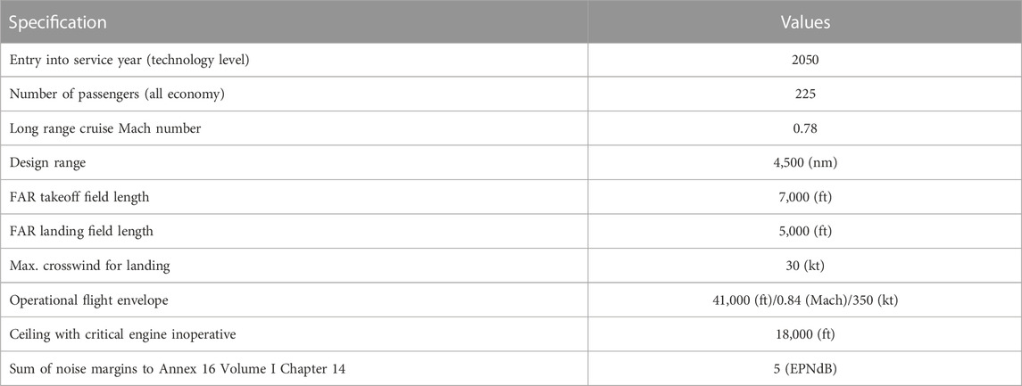
In the sample problem, a medium-size single-aisle subsonic commercial transport airplane to be developed typically for trans-Atlantic routes was considered. The performance specifications of the airplane considered in the sample problem are presented in Table 3. Single-objective optimization to minimize the block fuel weight for the design mission was performed. For the mission profile, a typical profile for commercial transport airplanes was assumed.
4.2 TEP specifications
In the sample problem, from the perspective of flight safety, the TEP system on the left wing and that on the right wing were assumed to be electrically independent, in order to exclude the possible “common-mode failures” that could lead to a simultaneous loss of all propulsive power of an airplane. Hence, the electric power to drive each RF was assumed to be supplied only by the TF on the same wing. Under such an assumption, the TF on a wing becomes the critical engine; when the TF loses power, the associated RF on the same wing loses power. Therefore, in the sample problem, “critical engine inoperative” means “a simultaneous loss of power of both the TF and RF on the same wing.”
The specific power (kW/kg) is an indicator that represents the weight performance of TEP devices National Academies (2016). In the sample problem, a parametric study of the weight performance of the TEP devices on the airplane properties was performed, varying the specific power of the TEP devices, as detailed in Table 4. An AC system was assumed for simplicity. Five cases were studied; each airplane is referred to as TEP10, TEP20, TEP50, TEP100, and TEP∞, respectively. An identical specific power was assumed for both the generator and motor, as they are based on similar technologies. The weight of the circuit protection devices was included in the weight of the associated generator and motor, by definition. For the electrical power distribution wire, pure copper wire with density of 8.96 (g/cm3) and electrical resistivity of 2.23 (μΩcm) was assumed. The wire was assumed to be directly routed from the generator to the motor via the TF pylon, wing leading-edge, and RF pylon.
Regarding electrical system voltage, a higher electrical system voltage generally provides a lighter electrical system. However, the system voltage is limited by the Paschen curve, which gives the breakdown voltage National Academies (2016). Modern commercial transport airplanes, such as the Boeing 787 and Airbus A350, use 230 Vac for the AC system Sarlioglu and Morris (2015). A significant increase in the electrical system voltage may be unrealistic, as has been pointed out in National Academies (2016). In the sample problem, 460 Vac was assumed for the system voltage of the TEP system, assuming a moderate technological advance from 230 Vac currently used in commercial transport airplanes.
From the perspective of system integration of an airplane, electro-magnetic interference (EMI) is an issue SAE International (2022). The electric devices and power lines operating at kiloampere level may cause serious EMI on the electronic devices and signal lines operating at milliampere levels, thus necessitating extensive EMI shielding. If the TEP devices are installed in the fuselage, where numerous avionics and signal lines are normally installed, an additional weight penalty due to the EMI shielding may need to be considered. In the sample problem, because the TEP devices are installed on the wing, where avionics are seldom equipped, no additional weight penalty due to EMI shielding was assumed.
The loss of work in the electrical system turns into heat, increasing the temperature of the electrical devices. As the propulsive work of the TEP system is relatively large, the temperature rise is significant and thermal management becomes an issue Schiltgen et al. (2016). In conventional commercial transport airplanes, the devices of the propulsion system are normally cooled by heat exchange between the oil circulating in the propulsion system and the fuel supplied from the wing fuel tank. In such an architecture, part of the work lost at the propulsion system is recovered by the fuel and, eventually, the thermal efficiency of the propulsion system is improved Rolls-Royce (2015). If the TEP devices are installed in the fuselage, a dedicated cooling system would be necessary and an additional weight penalty for cooling may need to be considered. In the sample problem, because the TEP devices are installed on the wing, where the existing TF cooling system is available, no additional weight penalty due to TEP device cooling was assumed.
To decelerate a commercial transport airplane on the ground, both thrust reversers and wheel brakes are normally used. Thrust reversers are effective at high speeds, while wheel brakes are effective at low speeds. The thrust reverser of a commercial transport airplane is a relatively heavy device Wells et al. (2017). Because reversal of the RF thrust is considered to be performed by switching its electrical circuit, no dedicated thrust reverser was assumed for the RF in the sample problem.
4.3 Optimization method
In the sample problem, a conceptual design optimization method using an evolutionary algorithm (EA), used for the conventional commercial transport airplanes in Takami and Obayashi (2022b), was used as well for the commercial transport airplanes with the TEP. EAs are robust and, therefore, they are suitable for simultaneously optimizing many design parameters within numerous constraints, such as is the case in airplane conceptual design optimization. The framework of the design parameter optimization process is shown in Figure 2. In the process, the proposal and evaluation of the design parameters are cycled repeatedly.
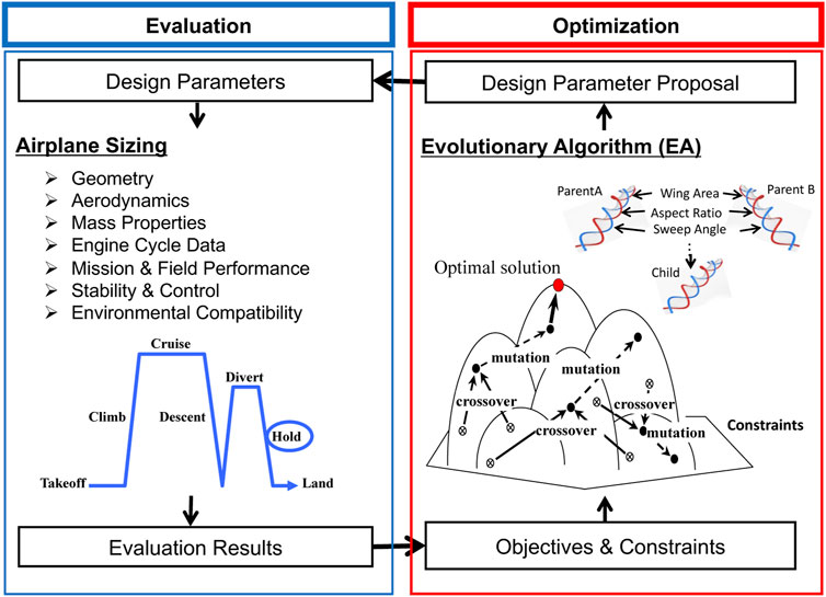
FIGURE 2. Design parameter optimization framework Takami and Obayashi (2022b).
To propose the design parameters, the computer code CMOGA (Constrained Multi-Objective Genetic Algorithm) developed by Tohoku University, was used. It is a constrained multi-objective optimization code, using the genetic algorithm (GA) Fonseca and Fleming (1993) as the optimizer and the more less-violations method (MLVM) Takami and Obayashi (2022a) as the constraint-handling technique (CHT). It reads sets of design parameters and resulting objectives and constraint violations, then, proposes new sets of desirable design parameters so that the objectives are improved within the constraints.
When EAs are used for design optimization problems with numerous constraints, such as airplane conceptual design optimization problems, the CHT becomes a key as feasible solutions are confined in a region with a limited extent, restricted by numerous contradicting constraints (Coello, 2002; Mezura-Montes and Coello, 2011). Robustness as well as efficiency is required to search for and find the desired feasible solutions within a limited timeframe. The MLVM, developed by the authors for EAs, is a robust and efficient CHT, where a strategy to keep solutions in a region next to the feasible region, called the acceptable region, preserves the diversity of solutions and improves the optimization level. Its strong search bias toward the acceptable region provides a robustness as well as an efficiency in solving design optimization problems with numerous constraints, such as airplane conceptual design optimization problems. The MLVM module, written in Fortran, is available online at Takami (2022).
To evaluate the design parameters proposed by CMOGA, the airplane-sizing computer code TCAD (Transport-Category Airplane Design program) developed by Mitsubishi Heavy Industries, Ltd., was used. It reads the design parameters and estimates major airplane characteristics, such as the geometry, aerodynamic characteristics, mass properties, propulsion system thermodynamic cycle properties and performances, mission performance, field performance, stability and control characteristics, and environmental compatibility.
The architecture of TCAD is similar to that of Smith et al. (2018). TCAD is structured with several functional modules, where each module is dedicated to a specific property of an airplane. The following is a brief description of the functional modules.
The aerodynamics module estimates aerodynamic forces, moments, and derivatives including the dynamic stability derivatives and control surface effectiveness, using a vortex lattice method (VLM) as by Miranda et al. (1977) and correcting for the zero-lift drags, such as the profile drag and friction drag, and the non-linear effects, such as the flow separation effects, as by Fink 1978; Hoerner 1965. The propulsion module estimates the installed engine performance by performing an engine cycle analysis for the uninstalled engine performance as by Kurzke and Halliwell (2018), considering the flat rating, and finally correcting for the installation drags (Covert, 1985; Seddon and Goldsmith, 1985). The masses and dimensions of the engine components are estimated based on the results of the engine cycle analysis Pera et al. (1977), selecting the most suitable material for each part in accordance with its thermal environment. The mass property module estimates the mass of airframe components using empirical formulae developed indigenously with statistical analyses on mass data of various airframe components as in Glatt (1974). For the inertia properties and CGs, a typical airframe component distribution on commercial transport airplanes is assumed. The performance module estimates the field performance and mission performance by integrating the equation of airplane motion as in Jenkinson et al. (1999), taking trims in roll, pitch, and yaw into consideration. The stability and control module estimates the stability and control characteristics, such as the natural frequencies and damping ratios of the longitudinal short-period response and lateral-directional Dutch roll modes, based on the linearized equations of airplane motion (McLean, 1990; Katayanagi, 2007; Scholz, 2022). The airport noise module estimates the airport noise levels by calculating the magnitudes of the engine and airframe noise sources in the form of broadband noises and tones based on the results of the engine cycle analysis (Zorumski, 1982; Stone et al., 2011; Stone et al., 2009), correcting for the propagation effects with the takeoff and landing trajectories from the performance module (Royal Aeronautical Society, 2011a; Royal Aeronautical Society, 2011b; Royal Aeronautical Society, 2019), and integrating them into the EPNLs as prescribed in ICAO (2017).
The computer system Affinity, installed in the Institute of Fluid Science at Tohoku University, was used to perform the optimization. Each node of Affinity has two 2.4 GHz CPUs (20 cores per CPU) and a 768 GB memory. A moderate population size of 32 was selected and the evaluations of the 32 individuals were performed in parallel in a single optimization loop, which was cycled to 2000 generations. Each optimization cycle took approximately 1 min and a single run took approximately 1.5 days. To ensure robustness, nine independent runs were performed.
The other EA setups used in the sample problem were identical to those used in Takami and Obayashi (2022b), as follows. The ranking was performed with the procedure in Fonseca and Fleming (1993). The fitness was calculated with a formula c (1 − c)rank−1 with c = 0.075. No fitness-sharing techniques were used. For the selection, the stochastic selection was used with the best-N elitism. For the crossover, the blended crossover was used with a probability of 1 and a distribution index of 0.5. For the mutation, the polynomial mutation was used with a probability of 0.05 and a distribution index of 5. In the MLVM, the acceptable region was inhibited until the first feasible solution emerged.
4.4 Results and discussion
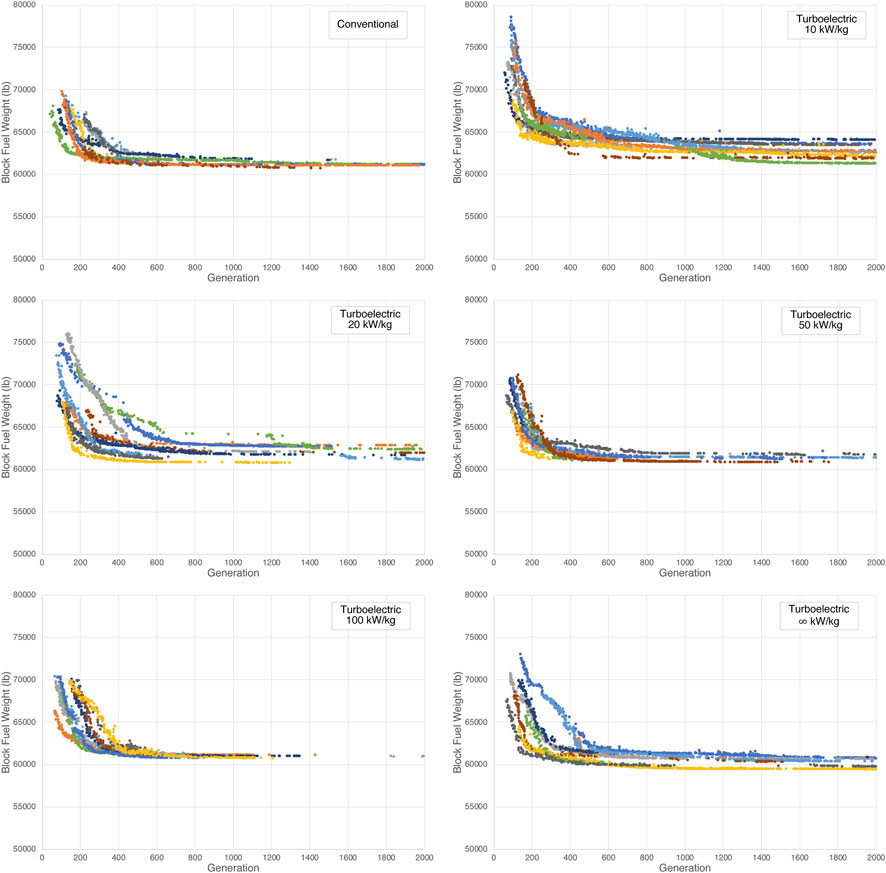
The optimization progresses (i.e., the development of feasible solutions) for the six cases—one for the conventional airplane and five for the TEP airplanes—are shown in Figure 3. In each graph, all of the nine independent runs are plotted.
In all cases, the optimization progresses converged within the pre-determined optimization cycle limit (2000). The feasible solutions of some runs failed to generate new feasible solutions beyond intermediate generations, as the feasible regions were considered to be too narrow for the preserved solutions to generate new feasible solutions, restricted by the contradicting constraints. Because feasible solutions occasionally fail to generate new feasible solutions beyond intermediate generations for the optimization method, the convergence was determined with engineering judgements. Automatic detection of convergence, using convergence criteria, is a future work.
Furthermore, the feasible solutions tended to converge prematurely, especially in cases with inadequate weight performance of the TEP devices. As the population (32) was relatively small with respect to the number of design parameters (21 for the TEP airplanes, 19 for the conventional airplane), the randomly generated initial population was considered not to be distributed widely enough in the design parameter space.
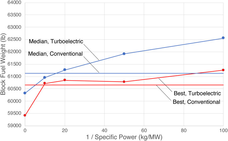
In Figure 4, the median and best objectives (block fuel weights) of the nine independent runs for the five cases with different weight performances of the TEP devices were compared with those for the conventional airplane. Note that the inverse of the specific power, kg per megawatt (kg/MW), is the abscissa in Figure 4, where the weight performance of a TEP device is better when the abscissa is smaller.
The best solution’s objectives of the TEP airplanes almost coincided with that of the conventional airplane, until the weight performance of the TEP devices was improved adequately to approximately below 10–20 kg/MW (specific power above 50–100 kW/kg). This is reasonable, as the best solution for inadequate weight performance of the TEP devices would be a TEP airplane with no RF mass flow; that is, a “conventional” airplane. Furthermore, specifically at 100 kg/MW (specific power of 10 kW/kg), the best solution’s objective for the TEP airplane was supposed to, but did not, coincide with that of the conventional airplane, which indicated that the EA was not able to find the optimal solution (“conventional airplane”), because the constraints became increasingly difficult to be met as the weight of the airplane grew due to the inadequate weight performance of the TEP devices.
For the medians, the objectives were improved as the weight performance of the TEP devices improved (smaller kg/MW). The crossover point—that is where the fuel performance of the TEP airplane and that of the conventional airplane crossed over—seemed to be around 10–20 kg/MW (specific power of 50–100 kW/kg), which is remarkably better than the specific power of 2–20 kW/kg expected to be achieved by the TEP devices in the near future (projected by National Academies (2016).
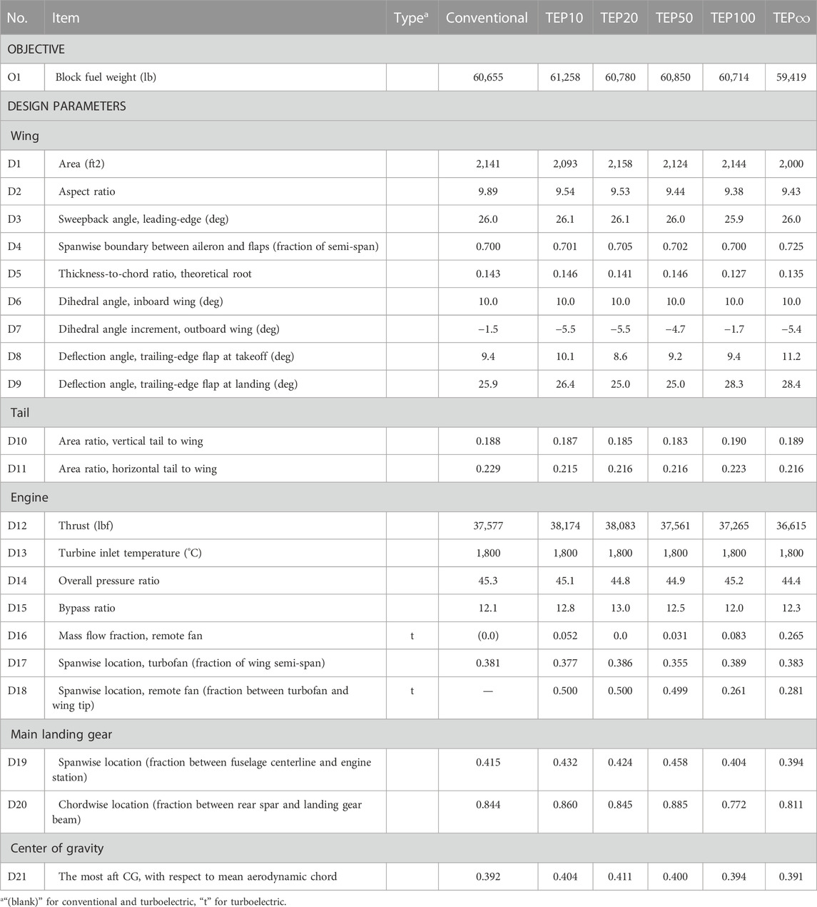
The optimized objective (block fuel weight) and design parameters are summarized in Table 5; the mass properties of the propulsion system, landing gear system, and thrust reverser, which are considered to be strongly inter-related from the perspective of airplane conceptual design, are summarized in Table 6. All properties are of the best solutions.
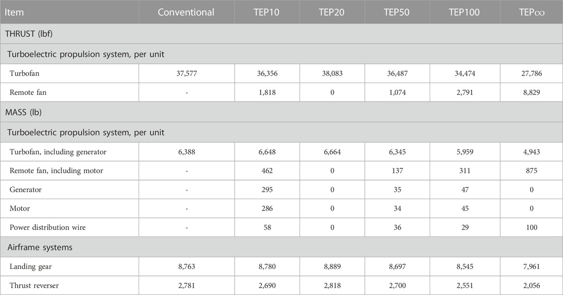
TABLE 6. Properties of the propulsion system, landing gear system, and thrust reverser of the best solutions.
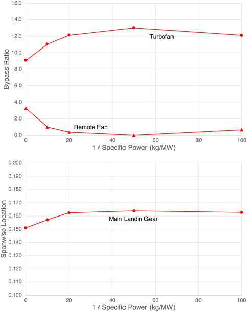
From the parameters listed in Table 5, the BPR of the TF [= D15 × (1-D16)], the BPR of the RF (= D15 × D16), and the spanwise location (fraction of the wing semi-span) of the main landing gear (= D17 × D19) are calculated and shown in Figure 5. Here, the spanwise location of the main landing gear represents the length of the main landing gear, as it is retracted sideways into the fuselage. As the weight performance of the TEP devices improved (smaller kg/MW), the BPR of the RF increased and that of the TF decreased. Accordingly, the spanwise location of the main landing gear was displaced toward inboard (i.e., shorter main landing gear), suggesting a configuration benefit of the TEP airplane.
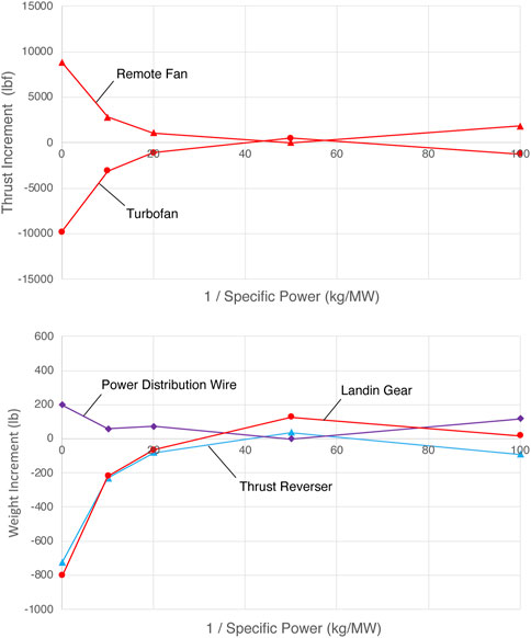
Based on the properties listed in Table 6, increments of the TF and RF thrusts and increments of the airframe component weights of the TEP airplane, from those of the conventional airplane, were calculated, as shown in Figure 6.
As shown in Figure 6, as the weight performance of the TEP devices improved to below the crossover range of 10–20 kg/MW (specific power of 50–100 kW/kg), the RF thrust increased and, conversely, the TF thrust decreased, indicating that allocating more power to the RF was beneficial for the TEP airplane. The weight of the turboelectric power distribution wire increased accordingly, as more electric power was conveyed to the RF from the LPT. The landing gear weight decreased with the TF thrust, due to the shorter landing gear length, as suggested by Figure 5. The thrust reverser weight also decreased in accordance with the TF thrust, as the weight of the thrust reverser is generally proportional to the TF thrust. At maximum, the resulting weight reductions were approximately 9% for the landing gear and 26% for the thrust reverser, respectively, which are notable benefits of the TEP airplane concept over the conventional airplane concept.
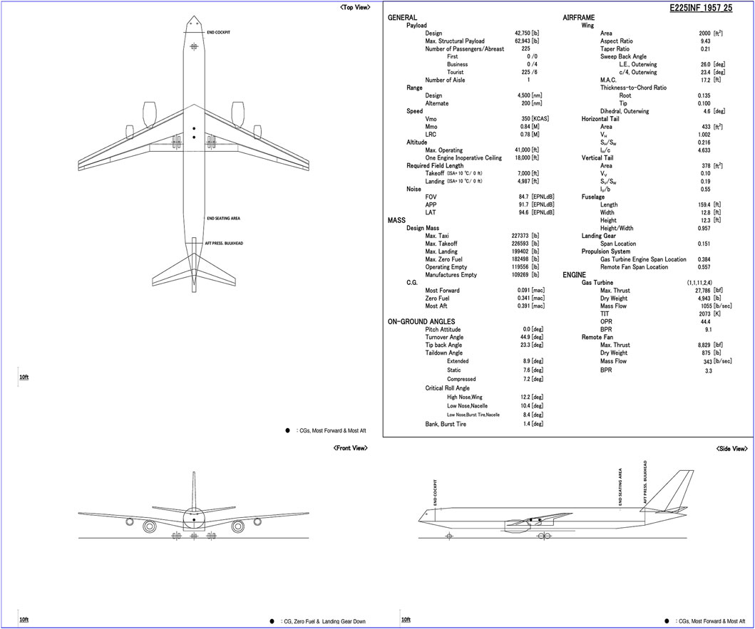
A three-view drawing of a TEP airplane concept with the TEP devices providing ideal weight performance (TEP∞) is shown in Figure 7, as a resulting solution from the conceptual design optimization problem formulated in this study for commercial transport airplanes with TEP.
Conceptual design optimization for commercial transport airplanes with TEP, with a reasonable fidelity and comprehensiveness suitable for industrial purposes, was considered to be feasible through use of the formulation proposed in this study, allowing for proper assessment of the benefits of the TEP.
5 Future work
Many TEP airplane concepts ever studied utilize the boundary layer ingestion (BLI) technology Hall et al. (2017) to improve their fuel efficiency. By installing the RF(s) at the aft end of the wing and/or fuselage and sucking the boundary layer with a reduced momentum into the RF(s), the installation drag is reduced and the installed propulsion system performance is improved Covert (1985); notably, this works not only for TEP, but also for conventional TF Drela (2012).
From the perspective of conceptual design optimization of commercial transport airplanes for industrial purposes, a reasonable fidelity and comprehensiveness is required to assess the benefits of the TEP properly. For an example, an RF at the aft end of the fuselage would decrease the tail-down angle of the airplane, increase the liftoff and touchdown speeds and, eventually, degrade the takeoff and landing performances of the airplane. Larger (and, hence, heavier) wing and high-lift devices and/or a longer (and, hence, heavier) landing gear may be required to meet the takeoff and landing performance requirements of the airplane, which could eventually cancel out the benefit derived from the TEP.
With minor modifications (possibly with no modifications), the design optimization problem formulated in this study for the airplane concepts using TEP can be applied to other airplane concepts using TEP, such as those with the RF at the aft end of the fuselage, utilizing the BLI technology. Investigating the complex but realistic effects of the BLI in such airplane concepts, applying the formulation developed in this study, is an aim for future work.
The FPR of the RF, which was assumed to be identical to that of the TF in this study, could be treated as an independent design parameter, possibly leading to better fuel efficiency and environmental compatibility. Including the FPR of the RF as a design parameter is also an aim for future work. Automatic detection of convergence in the optimization process, using convergence criteria, is an aim for future work as well.
6 Conclusion
A conceptual design optimization problem for commercial transport airplanes with TEP, with a reasonable fidelity and comprehensiveness suitable for industrial purposes, was formulated, in order to allow for proper assessment of the benefits of TEP.
As a sample problem, we performed conceptual design optimization of a TEP airplane concept in a tube-and-wing configuration with a TF and an associated RF on each (left and right) wing, varying the performance of the TEP devices. The results indicated that conceptual design optimization for commercial transport airplanes with TEP, suitable for industrial purposes, was considered to be feasible through use of the proposed formulation, allowing for proper assessment of the benefits of the TEP.
The results also indicated that, as the weight performance of the TEP devices improved, the BPR of the RF increased and the BPR of the TF decreased; accordingly, the spanwise location of the main landing gear was displaced toward inboard (for a shorter and, hence, lighter main landing gear). At maximum, the resulting weight reductions were approximately 9% for the landing gear and 26% for the thrust reverser, which are notable benefits of the TEP airplane concept.
The crossover point—that is, where the fuel performances of the TEP airplane and the conventional airplane cross over—seemed to be in the specific power range of 50–100 kW/kg for the TEP airplane concept considered in this study, which is remarkably better than the specific power projected for the near future.
Data availability statement
The datasets presented in this study can be found in online repositories. The names of the repository/repositories and accession number(s) can be found below: https://doi.org/10.6084/m9.figshare.21547149.v1.
Author contributions
Conceptualization, HT and SO; methodology, HT; software, HT; validation, HT; formal analysis, HT; investigation, HT; resources, SO; data curation, HT; writing—original draft preparation, HT; writing—review and editing, SO; visualization, HT; supervision, SO; All authors contributed to manuscript revision, read, and approved the submitted version.
Acknowledgments
The authors would like to thank Mitsubishi Heavy Industries, Ltd., for allowing us to use the computer code TCAD and to publish this paper.
Conflict of interest
The authors declare that the research was conducted in the absence of any commercial or financial relationships that could be construed as a potential conflict of interest.
The authors declare that Mitsubishi Heavy Industries, Ltd. provided the computer code TCAD for this study and granted permission to submit this article for publication under the software-use contract between the company and Tohoku university. The company was not involved in the study design, data collection, execution of analysis, interpretation of data, or the writing of this article.
Publisher’s note
All claims expressed in this article are solely those of the authors and do not necessarily represent those of their affiliated organizations, or those of the publisher, the editors and the reviewers. Any product that may be evaluated in this article, or claim that may be made by its manufacturer, is not guaranteed or endorsed by the publisher.
References
Airbus (2022). Aircraft characteristics: Airport operations and tech data – airport and maintenance planning. Airbus. Available at: https://www.airbus.com/en/airport-operations-and-technical-data/aircraft-characteristics.
Antonie, N., and Kroo, I. (2005). Framework for aircraft conceptual design and environmental performance studies. AIAA J. 43, 2100–2109. doi:10.2514/1.13017
Boeing (2022). Airplane characteristics for airport planning. Washington D.C: Boeing. Available at: https://www.boeing.com/commercial/airports/plan_manuals.page.
Bradley, M. K., and Droney, C. K. (2012). Subsonic ultra green aircraft research PhaseII: N+4 advanced concept development. Tech. Rep. NASA/CR-2012-217556, NASA. Available at: https://ntrs.nasa.gov/citations/20120009038.
Brelje, B. J., and Martins, J. R. (2019). Electric, hybrid, and turboelectric fixed-wing aircraft: A review of concepts, models, and design approaches. Prog. Aerosp. Sci. 104, 1–19. doi:10.1016/j.paerosci.2018.06.004
Coello, C. (2002). Theoretical and numerical constraint-handling techniques used with evolutionary algorithms: A survey of the state of the art. Comput. Methods Appl. Mech. Eng. 191, 1245–1287. doi:10.1016/S0045-7825(01)00323-1
Drela, M. (2012). Development of the d8 transport configuration. In AIAA 2011-3970, 29th AIAA applied aerodynamics conference (Honolulu, HI), 1–14. doi:10.2514/6.2011-3970
E. Covert (Editor) (1985). “Thrust and drag: Its prediction and verification,” Progress in astronautics and Aeronautics. 981 edn (New York, NY, USA: AIAA). doi:10.2514/4.865732
FAA (2021). Title 14 code of federal regulations. Washington D.C: U.S. Government Publishing Office. Available at: https://www.ecfr.gov/current/title-14.
Felder, J. L., Brown, G. V., Dae Kim, H. D., and Chu, J. (2011). “Turboelectric distributed propulsion in a hybrid wing body aircraft,” in International Society for airbreathing engines (ISABE 2011), ISABE-2011-1340. 1–25 (Gothenburg: Doc). ID 20120000856.
Fink, R. (1978). USAF stability and control DATCOM. Tech. Rep. AFWAL-TR-83-3048. Flight Dynamics Laboratory, Air Force Wright Aeronautical Laboratories. Available at: https://perma.cc/LQ5Y-RE5K.
Fonseca, C. M., and Fleming, P. J. (1993). “Genetic algorithms for multiobjective optimization: Formulation, discussion and generalization,” in Proceedings of the fifth international conference. Editor S. Forrest (San Mateo, CA), 1–8. Available at: https://perma.cc/SL3J-EF6U.
Gibson, A., Hall, D., Waters, M., Masson, B.P.:, Schiltgen Foster, T., et al. (2010). The potential and challenge of turboelectric propulsion for subsonic transport aircraft. In AIAA 2010-276, 48th AIAA Aerospace sciences meeting including the new horizons forum and Aerospace exposition, 2010, Orlando, Florida, USA. 1–22. doi:10.2514/6.2010-276
Glatt, C. (1974). Waats - a computer program for weights analysis of advanced transportation systems. Tech. Rep. NASA CR-2420, NASA. Available at: https://ntrs.nasa.gov/citations/19740027176.
Greitzer, E., Bonnefoy, P., delaRosaBlanco, E., Dorbian, C., Drela, M., Hall, D., et al. (2010). N+3 aircraft concept designs and trade studies, final report volume 1. Tech. Rep. NASA/CR—2010-216794/VOL1, NASA. Available at: https://ntrs.nasa.gov/citations/20100042401.
Hall, D., Huang, A., Uranga, A., Greitzer, E., Drela, M., and Sato, S. (2017). Boundary layer ingestion propulsion benefit for transport aircraft. J. Propuls. Power 33 (5), 1118–1129. doi:10.2514/1.B36321
Henderson, R., Martins, J., and Perez, R. (2012). Aircraft conceptual design for optimal environmental performance. Aeronautical J. 116, 1–22. doi:10.1017/S000192400000659X
ICAO (2017). “Environmental protection - volume I - aircraft noise,” in ICAO annex 16 to the convention on international civil aviation. 8 edn. Available at: https://digitallibrary.un.org/record/421894.
Jansen, R. H., Bowman, C., Jankovsky, A., Dyson, R., and Felder, J. (2017a). “Overview of nasa electrified aircraft propulsion research for large subsonic transports,” in AIAA 2017-4701, 53rd AIAA/SAE/ASEE joint propulsion conference 10-12 july 2017 (Atlanta, GA, 1–20. doi:10.2514/6.2017-4701
Jansen, R. H., Bowman, C., and Jankovsky, A. (2016). “Sizing power components of an electrically driven tail cone thruster and a range extender,” in 16th AIAA aviation technology, integration, and operations conference (Washington, D.C, 1–9. AIAA 2016-3766, AIAA AVIATION Forum 13-17 June 2016. doi:10.2514/6.2016-3766
Jansen, R. H., Duffy, K. P., and Brown, G. V. (2017b). “Partially turboelectric aircraft drive key performance parameters,” in 53rd AIAA/SAE/ASEE joint propulsion conference (Atlanta, Georgia, USA, 1–11. AIAA 2017-4702, AIAA Propulsion and Energy Forum 10-12 July 2017. doi:10.2514/6.2017-4702
Jenkinson, L., Simpkin, P., and Rhodes, D. (1999). Civil jet aircraft design. 1 edn. Washington, DC, USA: AIAA Education Series.
Katayanagi, R. (2007). Stability and control of airplanes. 1 edn. Japan: Morikita Publishing. (in Japanese).
Kim, H. D., Felder, J. L., Tong, M. T., and Armstrong, M. (2013). “Revolutionary aeropropulsion concept for sustainable aviation: Turboelectric distributed propulsion,” in ISABE-2013-1719, international society for air breathing engines (ISABE 2013), 1–12. Doc. ID 20140002510.
Kurzke, J., and Halliwell, I. (2018). Propulsion and power: An exploration of gas turbine performance modelling. 1 edn. Switzerland: Springer Cham. doi:10.1007/978-3-319-75979-1
McLean, D. (1990). Automatic flight control systems. Series in systems and control engineering. UK: Prentice Hall International.
Mezura-Montes, E., and Coello, C. (2011). Constraint-handling in nature-inspired numerical optimization: Past, present, and future. Swarm Evol. Comput. 1, 173–194. doi:10.1016/j.swevo.2011.10.001
Miranda, L., Elliot, R., and Baker, W. (1977). A generalized vortex lattice method for subsonic and supersonic flow applications. Tech. Rep. NASA CR-2865, NASA. Available at: https://ntrs.nasa.gov/citations/19800000236.
National Academies (2016). Commercial aircraft propulsion and energy systems research: Reducing global carbon emissions (2016). National Academies, Washington, DC. doi:10.17226/23490
Pera, R., Onat, E., Klees, G., and Tjonneland, E. (1977). A method to estimate weight and dimensions of aircraft gas turbine engines volume I: Method of analysis final report. Tech. Rep. NASA CR-135170, NASA. Available at: https://ntrs.nasa.gov/citations/19770018227.
Perez, R., and Behdinan, K. (2002). “Effective multi-mission aircraft conceptual design optimization using a hybrid multi-objective evolutionary method,” in 9th AIAA/ISSMO symposium on multidisciplinary analysis and optimization (Atlanta, GA, USA, 1–8. AIAA–2002–5464. doi:10.2514/6.2002-5464
Perez, R., Chung, J., and Behdinan, K. (2000). “Aircraft conceptual design using genetic algorithms,” in 8th symposium on multidisciplinary analysis and optimization (Long Beach, CA, USA. 1–11. AIAA–2000–4938. doi:10.2514/6.2000-4938
Raymer, D. (1989). Aircraft design: A conceptual approach. (Washington, DC, USA: AIAA Education Series), 1 edn Available at: https://perma.cc/U478-X52U
Roth, G., and Crossley, W. (1998). “Commercial transport aircraft conceptual design using a genetic algorithm based approach,” in 7th AIAA/USAF/NASA/ISSMO symposium on multidisciplinary analysis and optimization (St. Louis, MO, USA, 1–12. AIAA 98–4934. doi:10.2514/6.1998-4934
Royal Aeronautical Society (2011b). Estimation of lateral attenuation of air-to-ground jet or turbofan aircraft noise in one-third octave bands. London, United Kingdom: Royal Aeronautical Society. esdu 82027 edn.
Royal Aeronautical Society (2019). Evaluation of the attenuation of sound by an uniform atmosphere. London, United Kingdom: Royal Aeronautical Society. esdu 78002, amendment d edn.
Royal Aeronautical Society (2011a). The correction of measured noise spectra for the effects of ground reflection. London, United Kingdom: Royal Aeronautical Society. esdu 94035 edn.
Sadey, D. J., Taylor, L. M., and Beach, R. F. (2016). “Proposal and development of a high voltage variable frequency alternating current power system for hybrid electric aircraft,” in AIAA 2016-4928, 14th international energy conversion engineering conference july 25-27, 2016 (Salt Lake City, UT), 1–10. doi:10.2514/6.2016-4928
SAE International (2022). Guide to civil aircraft electromagnetic compatibility (EMC). SAE Int. ARP60493. Available at: https://www.sae.org/standards/content/arp60493/.
Saravanamuttoo, H., Rogers, G., Cohen, H., and Straznicky, P. (2009). Gas turbine theory. 6 edn. London, United Kingdom: Pearson Education Ltd.
Sarlioglu, B., and Morris, C. T. (2015). More electric aircraft: Review, challenges, and opportunities for commercial transport aircraft. IEEE Trans. Transp. Electrification 1 (1), 54–64. doi:10.1109/TTE.2015.2426499
Schiltgen, B., Green, M., Gibson, A., Hall, D., Cummings, D., and Hange, C. (2012). “Benefits and concerns of hybrid electric distributed propulsion with conventional electric machines,” in AIAA 2012-3769, 48th AIAA/ASME/SAE/ASEE joint propulsion conference and exhibit (Atlanta, Georgia, USA, 1–19. doi:10.2514/6.2012-3769
Schiltgen, B. T., Freeman, J., and Hall, D. W. (2016). “Aeropropulsive interaction and thermal system integration within the eco-150: A turboelectric distributed propulsion airliner with conventional electric machines,” in 16th AIAA aviation technology, integration, and operations conference (Washington, D.C, 1–18. AIAA 2016-4064, AIAA AVIATION Forum 13-17 June 2016. doi:10.2514/6.2016-4064
Scholz, D. (2022). Corrected: Mclean, d. automatic flight control systems; series in systems and control engineering. Available at: https://perma.cc/VPA5-JPP2.
Seddon, J., and Goldsmith, E. (1985). Intake aerodynamics. 1 edn. New York, NY, USA: AIAA Education Series.
Smith, H., Sziroczák, D., Abbe, G. E., and Okonkwo, P. (2018). The genus aircraft conceptual design environment. Proc. Institution Mech. Eng. Part G J. Aerosp. Eng. 233, 2932–2947. doi:10.1177/0954410018788922
Stone, J., Krejsa, E., and Clark, B. (2011). Enhanced core noise modeling for turbofan engines. Tech. Rep. NASA/CR-2011-217026, NASA. Available at: https://ntrs.nasa.gov/citations/20110013366.
Stone, J., Krejsa, E., and Clark, B. (2009). Jet noise modeling for suppressed and unsuppressed aircraft in simulated flight. Tech. Rep. NASA/TM-2009-215524, NASA. Available at: https://ntrs.nasa.gov/citations/20090015381.
Takami, H. (2022). Mlvm, a constraint-handling technique for evolutionary algorithms ”more less-violations method (mlvm). Available online: https://github.com/hikarutakami/MLVM.
Takami, H., and Obayashi, S. (2022a). A comparator-based constraint handling technique for evolutionary algorithms. AIP Adv. 12, 055229. doi:10.1063/5.0090572
Takami, H., and Obayashi, S. (2022b). A formulation of the industrial conceptual design optimization problem for commercial transport airplanes. MDPI Aerosp. 9 (9), 487. doi:10.3390/aerospace9090487
US Department of Defence (1980). Flying qualities of piloted airplanes. Virginia: US Department of Defence. MIL–F–8785C. Available at: https://perma.cc/FN56-6YAG.
Vratny, P., Kuhn, H., and Hornung, M. (2017). Influences of voltage variations on electric power architectures for hybrid electric aircraft. CEAS Aeronautical J. 8 (1), 31–43. doi:10.1007/s13272-016-0218-z
Wells, D. P., Horvath, B. L., and McCullers, L. A. (2017). The flight optimization system weights estimation method. Tech. Rep. NASA/TM-2017-219627/Volume I, NASA.
Welstead, J. R., and Felder, J. L. (2016). “Conceptual design of a single-aisle turboelectric commercial transport with fuselage boundary layer ingestion,” in AIAA 2016-1027, AIAA SciTech forum 4-8 january 2016 (San Diego, California: USA 54th AIAA Aerospace Sciences Meeting), 1–17. doi:10.2514/6.2016-1027
Zorumski, W. (1982). Aircraft noise prediction program theoretical manual. Tech. Rep. NASA TM-83199 Part 1, NASA. Available at: https://ntrs.nasa.gov/citations/19820012072.
Nomenclature
Abbreviations
AC alternating current
BLI boundary layer ingestion
BPR bypass ratio
CHT constraint handling technique
DC direct current
EA evolutionary algorithm
EMI electromagnetic interference
EPNdB effective perceived noise in decibel
FPR fan pressure ratio
GA genetic algorithm
LPT low-pressure turbine
NASA National Aeronautics and Space Administration
OPR overall pressure ratio
RF remote fan
TEP turboelectric propulsion
TF turbofan
TIT turbine inlet temperature
In Table 2
CAP control anticipation parameter
CG center of gravity
FAR Federal aviation regulations
MIL military specifications
V1 takeoff decision speed
V2 takeoff safety speed
VEF engine failure speed
VFTO final takeoff speed
VLOF liftoff speed
VMC minimum control speed, in the air
VMCL minimum control speed, in the landing configuration
VMCG minimum control speed, on the ground
VMU minimum unstick speed
VR rotation speed
VREF landing reference speed
VSR stall speed, reference
t30 time to achieve 30° bank angle change
ζd damping ratio, dutch roll
ζSP damping ratio, short-period response
Keywords: conceptual design, transport airplane, turboelectric propulsion, optimization, evolutionary algorithm
Citation: Takami H and Obayashi S (2023) A formulation of industrial conceptual design optimization problem for commercial transport airplanes with turboelectric propulsion. Aeroesp. Eng. 2:1113646. doi: 10.3389/fpace.2023.1113646
Received: 01 December 2022; Accepted: 20 February 2023;
Published: 10 March 2023.
Edited by:
Obula Reddy Kummitha, Padmasri Dr. B. V. Raju Institute of Technology, IndiaReviewed by:
Benard, Institut Supérieur de l’Aéronautique et de l’Espace (ISAE-SUPAERO), FranceAlessandro Ceruti, University of Bologna, Italy
Copyright © 2023 Takami and Obayashi. This is an open-access article distributed under the terms of the Creative Commons Attribution License (CC BY). The use, distribution or reproduction in other forums is permitted, provided the original author(s) and the copyright owner(s) are credited and that the original publication in this journal is cited, in accordance with accepted academic practice. No use, distribution or reproduction is permitted which does not comply with these terms.
*Correspondence: Hikaru Takami, dGFrYW1pLmhpa2FydS5zNkBkYy50b2hva3UuYWMuanA=
†ORCID: Hikaru Takami, orcid.org/0000-0002-5855-6568; Shigeru Obayashi, orcid.org/0000-0003-3876-1908
 Hikaru Takami
 Shigeru Obayashi2†