 Haiyang Wang
 Yifei Pi2
 Xie George Xu
- 1Institute of Nuclear Medical Physics, University of Science and Technology of China, Hefei, China
- 2Radiation Oncology Department, The First Affiliated Hospital of Zhengzhou University, Zhengzhou, China
- 3Technology Development Department, Anhui Wisdom Technology Co., Ltd., Hefei, China
- 4Radiation Oncology Department, First Affiliated Hospital of University of Science and Technology of China, Hefei, China
Purpose: To investigate the influencing factors of total skin irradiation (TSI) with helical tomotherapy for guiding the clinical selection of the suitable parameters and optimizing the plan quality and efficiency.
Materials and Methods: Six patients with mycosis fungoides (MF) who received TSI were retrospectively selected. They were all dressed with 5 mm thick diving suits during the CT scan and treatment as a bolus to increase the superficial dose through buildup. The dose prescription was 24 Gy in 20 fractions and 5 times per week. During the planned pretreatment, Ring0, Ring1, Ring2, Ring3, and Ring4 of 1 cm thick away from the planning target volume (PTV) at the distances of 0, 1, 2, 3, and 4 cm and other normal tissues (NTs) were generated, respectively. The auxiliary structures were completely blocked during planning; while the field widths were 5 and 2.5 cm, the pitches were 0.287 and 0.215, the modulation factors were 4 and 3, and the other parameters remained consistent. Finally, the dose parameters of PTV and auxiliary structures, as well as the beam on time (BOT) and gantry period, were compared and analyzed.
Results: when the auxiliary structures were completely blocked with distance to PTV (dPTV) above 3 cm were used, the mean dose (Dmean), conformity index (CI), and heterogeneity index (HI) of the PTV met the clinical requirements. As the dPTV gradually increased, the BOT decreased while the volume of normal tissue that received excessive radiation increased correspondingly. If the dPTV was less than 3 cm, the clinical requirements were not met. The field widths (FWs), pitches, and modulation factors (MFs) had no effect on PTVmean and the HI. The FW of 2.5 cm was slightly better than 5 cm for the CI. The FW and MF had a significant impact on the BOT, which gradually increased with decreasing FW and increasing MF. Pitch had no effect on the BOT.
Conclusion: During planning with TSI patients, dPTV is the key factor that has a significant influence on the plan quality. We found that the plan with the dPTV above 3 cm can meet clinical objectives. The BOT increases as the dPTV increases. The FWs also have an effect on the CI and BOT. Therefore, it is necessary to comprehensively balance these factors to optimize the quality and efficiency of the plan. We also found that different MFs and pitches have no obvious effect on the results.
Introduction
Cutaneous T-cell lymphoma (CTCL), a relatively rare group of mature T-cell lymphomas, mainly manifests in the skin and accounts for about 71% of all primary cutaneous lymphomas. The common subtype of CTCL is mycosis fungoides (MF) (1). According to the latest statistics data from the National Cancer Institute (NCI) “Monitoring Epidemiology and Results,” CTCL (mainly MF) is currently increasing at a rate of 9.6 cases/million every year, and the incidence rate accounts for about 50% of CTCL (2). CTCL is usually highly radiosensitive, and the traditional treatment technique as well as one of the most effective methods for CTCL is total skin electron irradiation (TSEI) (3). At present, the dual-frame six-field irradiation technology developed by the Stanford University School of Medicine was mostly used; however, the long treatment distance requires the patient to stand and perform multifield irradiation with a rotating gantry, which is a burden for the patient (4). With the development of radiotherapy technology, especially the emergence of helical tomotherapy (HT) (5), which equips 51 equally spaced beam angles at 360-degree helical irradiation, the opening and closing of 64-leaf, pneumatically powered, binary multileaf collimator and translation motion of the treatment couch. These unique components endows HT with many advantages, such as a high degree of freedom, power in dose optimization and the treatment of an ultralong target (160 cm × 40 cm) (6), so HT is very suitable for the treatment of long and complex targets, such as total body multiple metastatic irradiation, craniospinal radiotherapy, total body irradiation, and total marrow irradiation (7). Moreover, compared to the traditional TSEI in which patients are required to stand all the time during treatment, the lying-down treatment method of TSI makes patients less fatigued, more comfortable, and get a better dose distribution. Hsieh CH et al. (8) used a 3 mm diving suit as a bolus. The dPTV was 2.5 cm and the FW, pitch, and MF were 2.5, 0.287, and 3.5 cm; Haraldsson A et al. (9) used a 7 mm diving suit as bolus, and the dPTV was 3 cm as, the FW, pitch and MF was 5, 0.2, and 2.3 cm, respectively, they were designing plans only to meet clinical objectives without a further study of the optimal planning and the effect of other parameters on the results. The purpose of this work is to study the influence of the different parameters and auxiliary structures of the complete mode on the plan quality, in order to guide the clinical selection of the best parameters combination and improve the plan quality and performance.
Materials and Methods
Patients’ Clinical Characteristics
The first six consecutive patients with MF who received TSI between 2020 and 2021 at the Department of Radiotherapy of the First Affiliated Hospital of Zhengzhou University were retrospectively selected, as all patients had pathologically confirmed.
Bolus
Six patients were dressed in the 5 mm diving suit as a bolus. The diving suits were tailored according to the patients’ external shape to achieve a tight wrap around the body.
Immobilization
Patients dressed with a 5 mm diving suit were immobilized in a supine position (Figure 1). Thermoplastic masks were used for the head and neck, thorax, and abdomen, while the lower limbs were immobilized in a vacuum cushion. The upper marks and lower masks are located near the patient’s belly button and near the patient’s patella, respectively, and the segment line made of lead is located around 10 cm above the patella as the boundary between the upper and lower target.
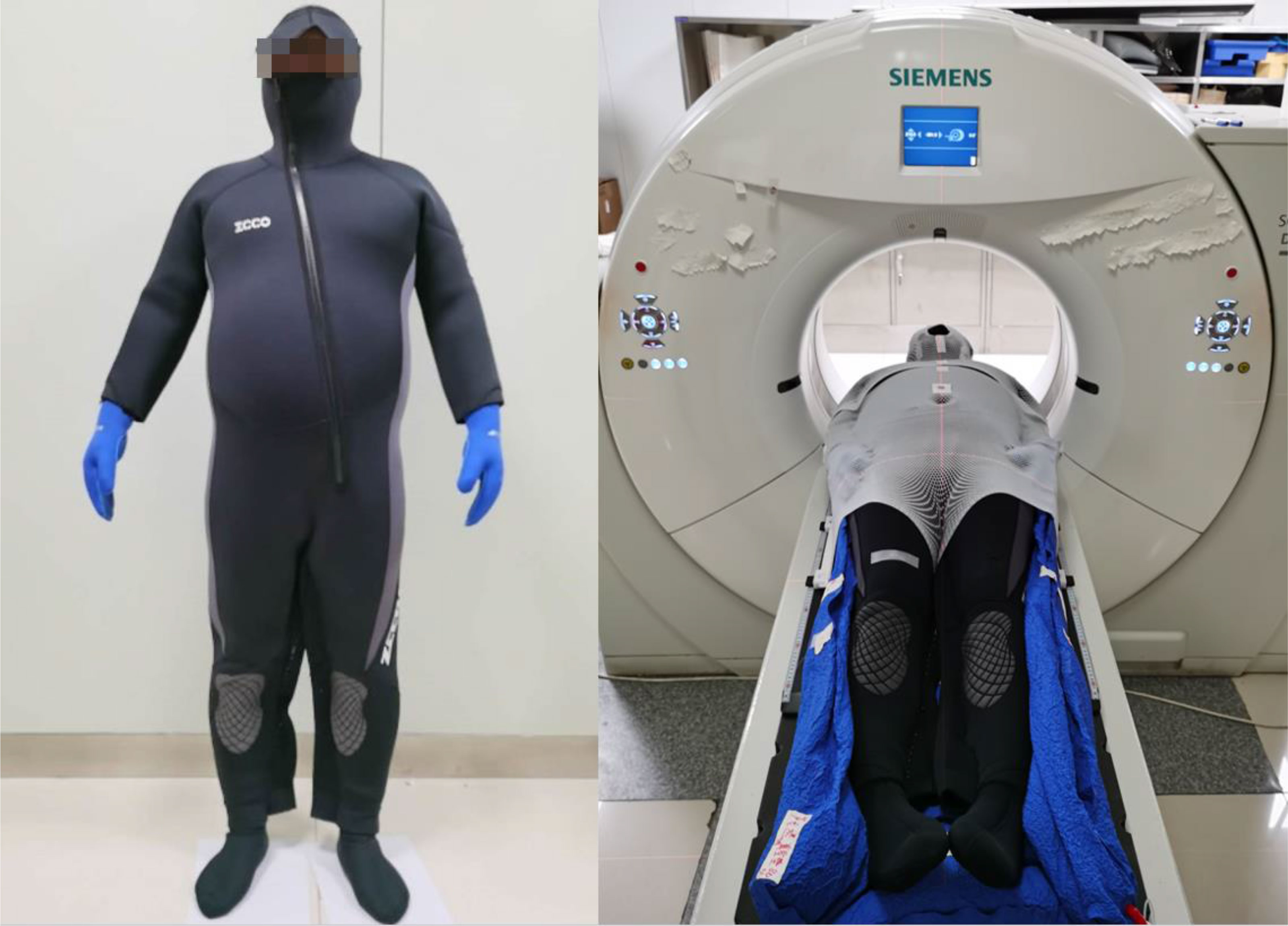
Figure 1 Patient dressed with a 5 mm diving suit.
Image Acquisition at Simulation
Helical computed tomography (CT) scans (SOMATOM Definition AS40; Siemens) were performed under the following condition: a scan and reconstruction slice thickness of 5 mm. The patients were scanned in upper and lower segment, respectively. The upper segments were scanned from the skull to 10 cm below the boundary, while the lower segments scanned from the toes to 10 cm above the boundary.
Delineation of Target Volumes and Organs at Risk
The target volumes and organs at risk (OARs) for all patients were delineated by radiation oncologists based on the planning CT according to the ICRU50 (10) and ICRU62 reports (11). The clinical target volume (CTV) was defined between the skin surface and 5 mm below it (8). The planning target volume (PTV) was generated by expanding the CTV with 5 mm and then retracting it with 3 mm in the outside region, considering the setup error and dose buildup effect. OARs were delineated based on the ICRU 83 report (12), primarily including the total bone marrow (head and neck bones, upper limb bones, ribs, spine, pelvis, lower limb bones), eyeballs, lens, parotid, lungs, heart, kidneys, liver, bladder, rectum, spinal cord, and brainstem. The junction between the upper and lower sections of TBI had been studied in our previous publication (13); the dose in the overlap region was mostly homogeneous when the distance was equal to the FW.
Plan Designs
The planning CT and contoured structures of each patient were transferred to the treatment planning workstation (Version 5.1.6; Accuray, Sunnyvale, CA, USA) for planning. The dose prescription was 24 Gy in 20 fractions and 5 times per week. The PTV gradually retracted from 1 to 5 cm by a 1 cm step to create the ring-shape auxiliary structure as Ring0, Ring1, Ring2, Ring3, and Ring4 and the solid NT auxiliary structures as NT (Figure 2). The auxiliary structures were used as an assistant tool for plan optimization to achieve the dose objectives. During planning, all the auxiliary structures were set to a complete mode one by one (Figure 3) with the FW of 5 and 2.5 cm, pitches of 0.287 and 0.215, and MF of 4 and 3. The dose grid was 0.195 cm × 0.195 cm. Plans were designed by combining different parameters and auxiliary structures; the other parameters remained consistent. Since the planning quality did not improve significantly more than 100 iterations, the final dose calculation was performed after 100 iterations for each plan.
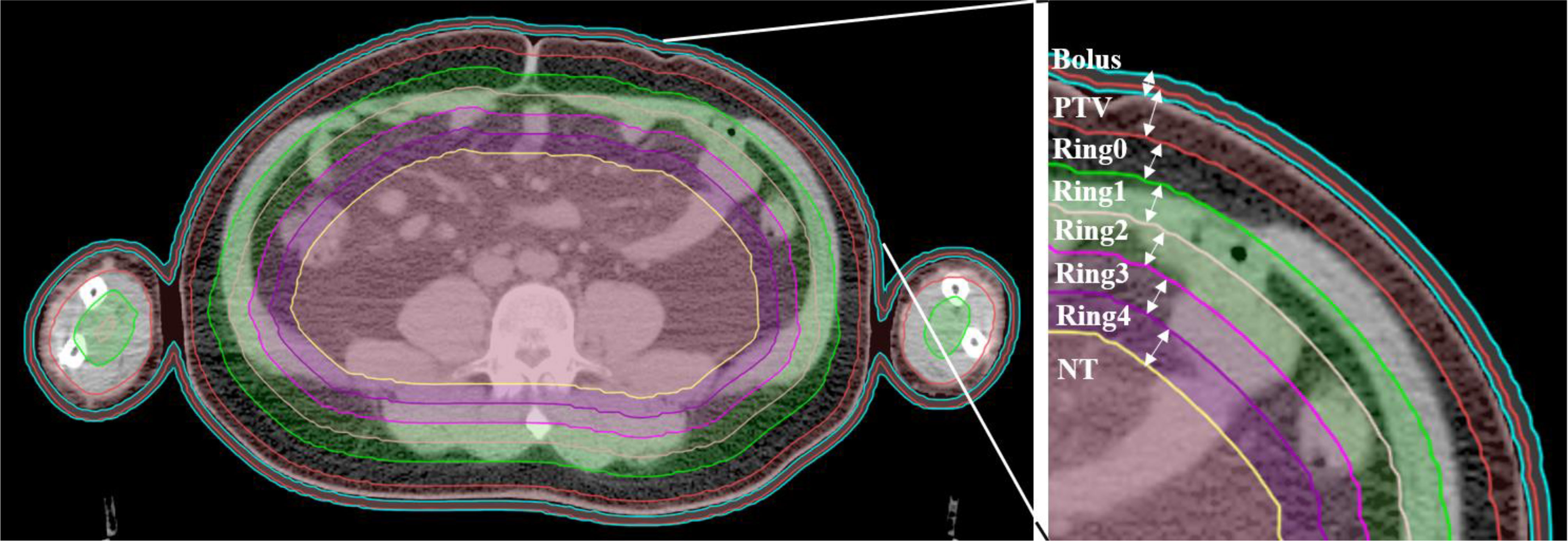
Figure 2 Structure sketches of the auxiliary structure Ring0, Ring1, Ring2, Ring3, Ring4, and NT as well as the PTV and bolus (the diving suit).
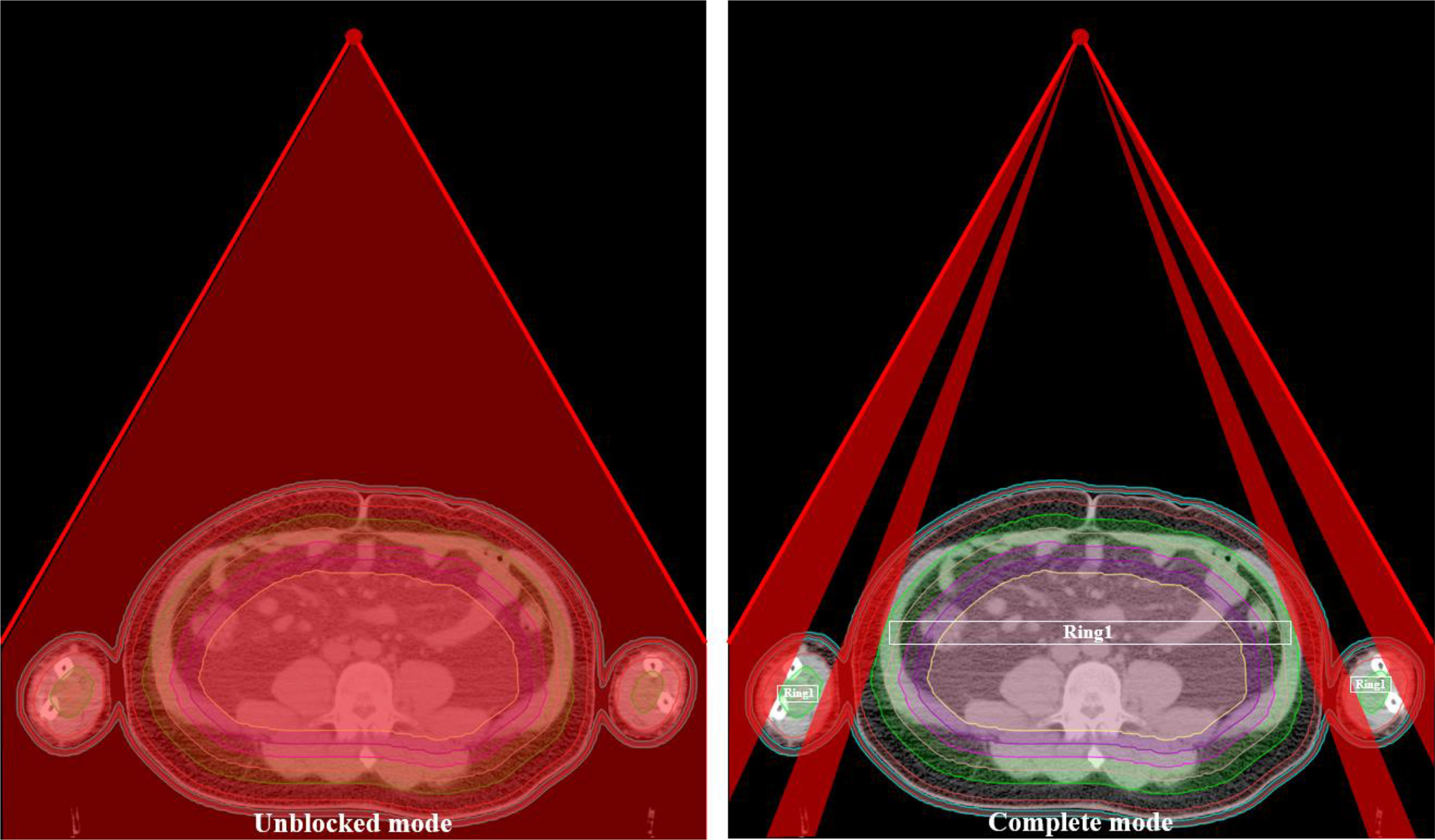
Figure 3 The ray distribution of the unblocked mode and complete mode of the Ring1.
Assessment of Plan Parameters
The parameters assessed for the patients included the mean dose, heterogeneity index (HI), and conformity index (CI) of the target volume. At least 95% of the target volumes reached the prescribed dose. The HI was calculated using the formula, HI=D5%/D95%, D5% is the dose received by 5% of the PTV volume, D95% is the dose received by 95% of the volume of the PTV. The HI value greater than 1 represents the heterogeneity dose distribution of the target volume. The CI was obtained using the following Paddick equation (14): CI=VT,ref/VT × VT,ref/Vref, VT,ref is the target volume covered by the prescription isodose (cm3), Vref is the volume encompassed by the prescription isodose (cm3), and VT is the target volume (cm3). The CI value is closer to 1, the better dose conformity of the target volume.
Statistical Analysis
All statistical analyses were performed using SPSS version 19.0 for Windows (IBM Corp., Armonk, NY, United States). The data results were expressed as mean ± standard deviation (x ± s). The graphics were plotted by Origin version 8.0 for Windows (OriginLab Corp., Northampton, MA, United States).
Results
Patients’ Characteristics Comparisons of Dosimetric Parameters of Target Volumes
All the treatment plans met the requirement of 95% prescribed dose coverage of the target volume. Figure 4 shows the trend of the PTVmean (A), HI (B), and CI (C) under different auxiliary structures (Ring2, Ring3, Ring4, NT) of the complete mode with FW=5 cm/2.5 cm, Pitch=0.287/0.215, MF=4/3. It can be clearly observed from Figure 4 PTVmean (A): with the dPTV increasing, the mean dose to PTV gradually approaches the prescribed dose. When the dPTV is above 3 cm, the mean dose to PTV meets the clinical requirements that reach the prescribed dose; FW, Pitch, and MF had no effect on the results. Figure 4 HI (B) shows the result: when the dPTV is above 3 cm, the HI of the target can be better; the result was consistent with PTVmean. Figure 4 CI (C) shows that the auxiliary structures have no obvious influence on the CI of the target. Relatively speaking, an FW of 2.5 cm was slightly better than 5 cm, but Pitch and MF had no effect on the CI. The most important influencing factor on the dose distribution of the target was the auxiliary structure of the complete mode; the recommended distance was greater than or equal to 3 cm, while FW, Pitch, and MF have no significant effect on the results. A total of 6 patients with MF received TSI; 4 patients are men and 2 patients are women as shown in the table. The age range and average are 31–65 and 51, the height range and average are 155–172 cm and 165 cm, and the weight range and average are 40–95 kg and 64.7 kg. Detailed information were listed in Table 1.
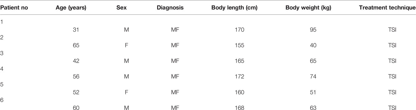
Table 1 6 patients’ characteristics.
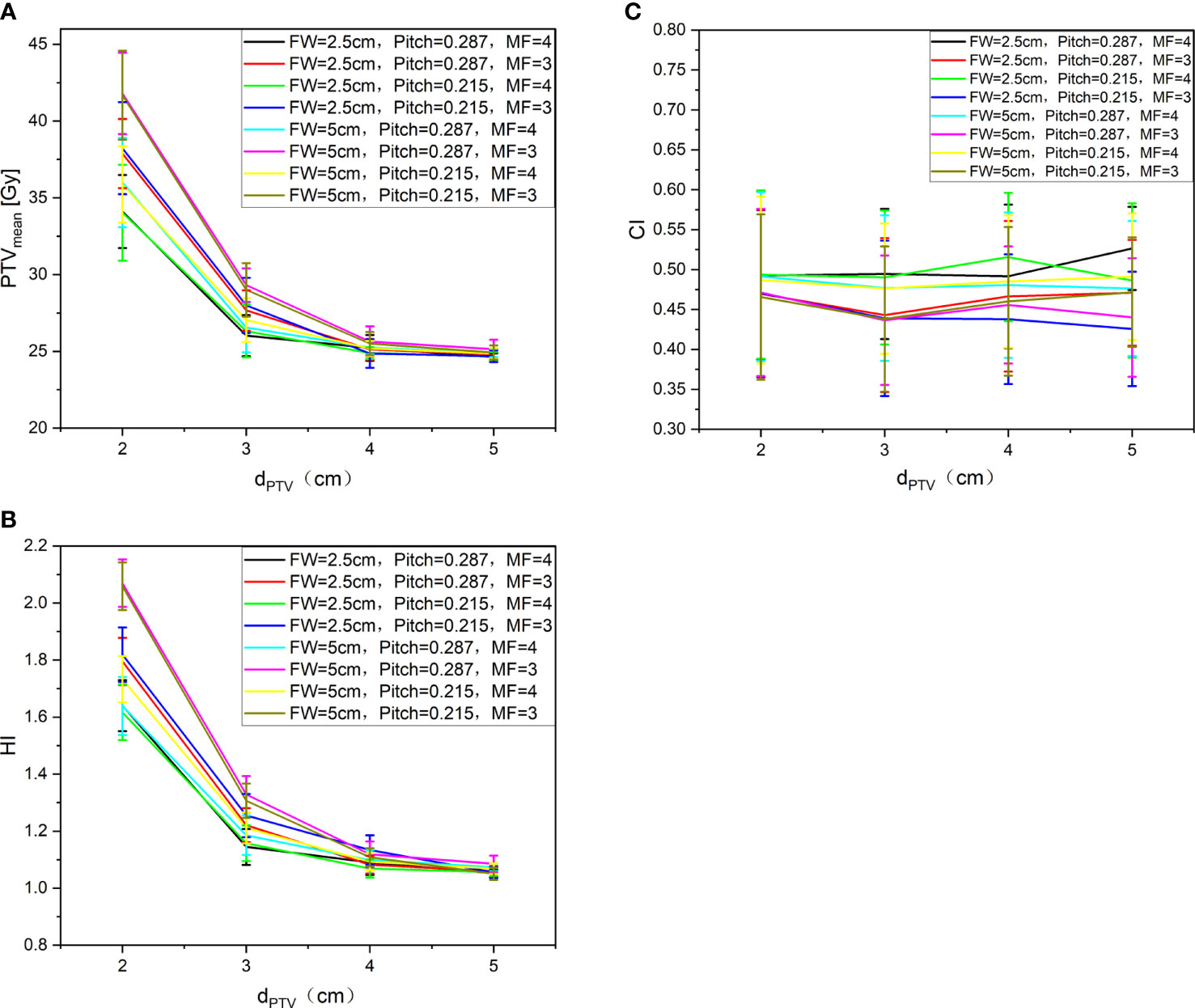
Figure 4 PTVmean (A), HI (B), and CI (C) with different auxiliary structures completely blocked.
Comparisons of Dosimetric Parameters of Auxiliary Structure
Figure 5 shows the trend of the mean dose of Ring0 (A)、Ring1 (B)、Ring2 (C)、Ring3 (D)、Ring4 (E)、and NT (F) with auxiliary structures (Ring2, Ring3, Ring4, NT) of the complete mode, FW=5 cm/2.5 cm, Pitch=0.287/0.215, and MF=4/3. We can observe from Figure 5 that to ensure that the mean dose of the auxiliary structure Ring0, Ring1, Ring2, Ring3, Ring4, and NT reaches the prescribed dose, the dPTV must be greater than or equal to 3 cm. The figure Ring0 (A)、Ring1 (B)、and Ring2 (C) show that the goal auxiliary structures Ring0, Ring1, and Ring2 meet the above conditions, and the mean dose can reach the prescribed dose. In figures Ring3 (D)、Ring4 (E)、and NT (F), none of Ring3, Ring4, and NT meet the above conditions, and the mean dose is unable to reach the prescribed dose. This conclusion is consistent with results of the target, and FW, Pitch, and MF have no significant influence on the results.
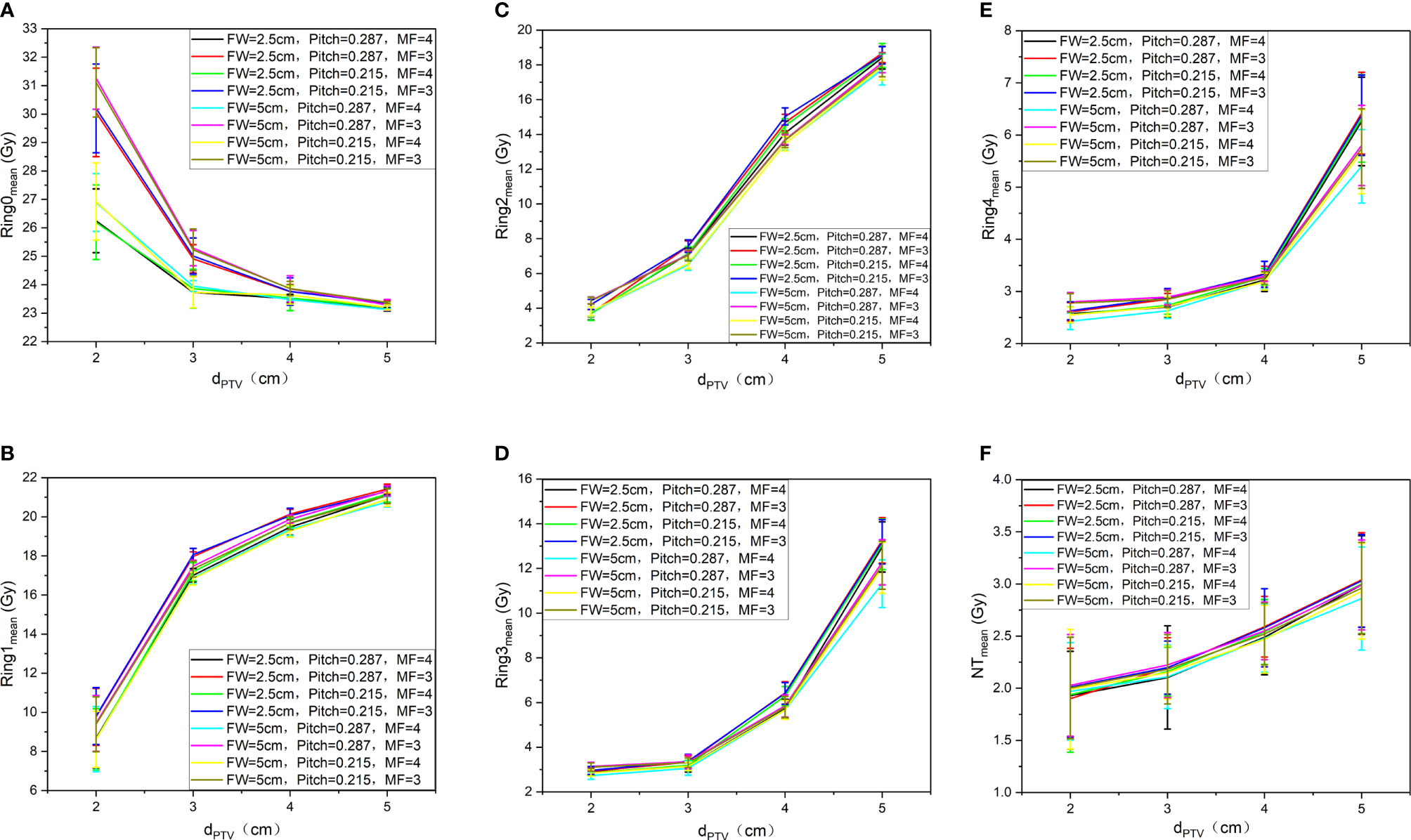
Figure 5 Trend of the mean dose of Ring0 (A), Ring1 (B), Ring2 (C), Ring3 (D), Ring4 (E), and NT (F) with auxiliary structures (Ring2, Ring3, Ring4, NT) of the complete mode, FW=5 cm/2.5 cm, Pitch=0.287/0.215, and MF=4/3.
Comparisons of Beams on Times and Gantry Periods
Figure 6 shows the trend of BOT (A) and GP (B) under different auxiliary structures (Ring2, Ring3, Ring4, NT) of the complete mode, FW=5 cm/2.5 cm, Pitch=0.287/0.215, and MF=4/3. We can observe that as the dPTV increases, BOT and GP are gradually reduced. When the dPTV is greater than or equal to 3 cm, the changing tends of BOT (A) and GP (B) are gentle; compared with 5 cm, the BOT for FW of 2.5 cm increased 86 ± 19%, but different MF and Pitch have no significant effect on the results.

Figure 6 Trend of BOT (A) and GP (B) under different auxiliary structures (Ring2, Ring3, Ring4, NT) of the complete mode, FW=5. cm/2.5 cm, Pitch=0.287/0.215, and MF=4/3.
In summary, when designing a TSI plan with helical tomotherapy, the most influential factor is the selection of the auxiliary structure in the complete mode. Only the dPTV above 3 cm can meet the clinical requirements. The BOT decreases with the gradual increasing of the dPTV. The FW has effect on the CI of the target and the BOT. Therefore, it is necessary to comprehensively balance these factors to optimize the quality and efficiency of the plan. We also concluded that different modulation factors and pitches have no obvious influence on the results.
Discussion
So far, many medical institutes have treated TSI patients with HT. Due to the lack of treatment guidelines and standards, the auxiliary structures of the complete mode and planning parameters determined by each institute for planning are quite different, which have a significant impact on the plan quality and efficiency. Hsieh CH et al. (8) were the first to achieve TSI with HT, a dPTV of 2.5 cm, an FW of 2.5 cm, Pitch of 0.287, and MF of 3.5 were used in their study. However, Haraldsson A et al. (9) selected a dPTV of 3 cm, with an FW of 5 cm, Pitch of 0.2, and MF of 2.3 for planning. Geurts M et al. (15)selected a dPTV of 5 cm, an FW of 5 cm, Pitch of 0.215, and MF of 3. Sarfehnia A et al. (16) selected a dPTV of 2 cm, FW of 5 cm, Pitch of 0.287, and MF of 2.5. Lin CT et al. (17) selected a dPTV of 1.8 cm on the phantom with an FW of 2.5 cm, Pitch of 0.287, and MF of 3.5. Geurts M et al. (15) selected a dPTV of 5 cm, with an FW of 5 cm, Pitch of 0.215, and MF of 3. Different institutes choose various parameters to design a TSI plan with HT in order to reduce the influence of human factors on the plan quality; the various auxiliary structures of the complete mode and planning parameters are studied one by one in this study to obtain the best combination between the auxiliary structures of the complete mode and planning parameters and forming treatment guidelines and standards.
All patients were dressed with a 5 mm diving suit as the bolus in this study because the 5 mm diving suit is the most common one in the market as the bolus; it is easy to obtain, and the research results will be more universal. Mainly considering the low density of the diving suit (-400~-600HU), the impact of dose is relatively small within a relatively small thickness variation range (such as within 1 mm), and the conclusion can be used for reference. However, for the diving suit of different materials (especially with large density differences) as the bolus, more work is required for a robust conclusion.
The PTV gradually retracts into the body to form 1 cm thick auxiliary structures; the volume from the distance 0, 1, 2, 3, and 4 cm and the remaining volume from the PTV are sequentially generated as the auxiliary structures of Ring0, Ring1, Ring2, Ring3, Ring4, and NT with a thickness of 1 cm. The auxiliary structures do not represent OARs or the PTV; they are only used as a tool for plan optimization to achieve dose constraints. At the same time, it is also used as a part of the plan evaluation to study the trend of the dose distribution of the auxiliary structures with distance. The auxiliary structures are formed by the stepwise movement distance of PTV into the body, 0, 1, 2, 3, and 4 cm and the remaining volume from the target sequentially are generated as Ring0, Ring1, Ring2, Ring3, Ring4, and NT auxiliary structures with a thickness of 1 cm. These structures are automatically generated by the physician workstation according to specific requirements, and will not be affected by human factors, so the research results and clinical applications are more universal and representative.
In this study, the auxiliary structures of Ring0, Ring1, Ring2, Ring3, and Ring4 with a thickness of 1 cm are generated and the remaining normal tissue volume is defined as NT. Only 5 auxiliary structures are generated, and no more auxiliary structures are made in this work; because the minimum cross-section of the head and neck is approximately 10 cm, more auxiliary structures are not able to be generated. At the same time, the maximum distance of auxiliary structures used in related research is 5 cm according to the literature (15). The auxiliary structures selected are 1 cm thick in this study, and no thinner auxiliary structures (such as 8, 5, and 3 mm) are generated. The main consideration is that the research results with thinner auxiliary structures are possibly more refined compared with 1 cm, but the change trend of the results should be consistent.
This study only contains data for Ring2, Ring3, Ring4, and NT without Ring0 and Ring1. The main reason is that the distance from the PTV is too small to optimize the plan when the Ring0 and Ring1 auxiliary structures are used in the complete mode, so no statistical results are available for Ring0 and Ring1.
This work studies the impact of auxiliary structures and planning parameters on the results. The analysis of the results employs the auxiliary structures of Ring0, Ring1, Ring2, Ring3, Ring4, and NT for evaluation instead of using the actual OARs for statistics. The analysis mainly investigated six patients who have large differences in height, weight, and weight, these factors may have a great impact on OARs. For example, the larger weight means the more fat under the skin can protect the OARs better. The lighter weight is unable to protect OARs due to the less fat under the skin; therefore, it is not universal. The only variable of the auxiliary structures selected in this work is the dPTV, which means that fewer influencing factors could disturb the results and this work can well reflect the dose drop gradient of the body and is more universal and representative.
In order to study the influence of various parameters on the results, this work chooses FW=5 cm/2.5 cm, Pitch=0.215/0.287, MF=3/4, mainly from clinical reports and related research literature as references. The FWs of 5 and 2.5 cm are defined based on the execution efficiency; The pitches of 0.215 and 0.287 are applied considering the GP; The MFs of 3 and 4 are used based on the actual complexity of the plan. Calculation grid affects were studied with one patient (dPTV=4 cm, FW=5 cm, MF=3, pitch=0.287), the results showed that PTVmean was decreased (26.75 ± 1.47 Gy, 26.54 ± 1.43 Gy, 20.30 ± 1.41 Gy), but GPs (29.29, 29.70, and 30.20 s) and BOTs (2,364.10, 2,395.20, and 2,434.90 s) increased from fine to coarse calculation resolution. Considering that the calculation grid affects the accuracy of dose calculation, this work adopts the finest grid of 0.195 cm × 0.195 cm. During the experiment, only one variable was changed at a time, and the other variables remained unchanged. The dose calculation for the plan is performed after 100 iterations to ensure the consistency and repeatability of the results.
Haraldsson A et al. (9) used a phantom for the robustness of plan by adding an 8 mm virtual bolus outside the skin for planning optimization; the impact of the positioning error within the 10 mm range on the treatment accuracy is eliminated. Geurts M et al. (15) used an anthropomorphic phantom and added a separate “flash” rind by expanding the external contour by 1.0 cm. The density of the flash structure was overridden to 0.2 g/cm3, and a dose constraint equal to the target was chosen. The plan quality began to significantly degrade if the phantom was offset by more than 10 mm using 7.0 and 10 mm target and flash thicknesses. Takenaka R et al. (18) performed total scalp irradiation, a virtual bolus with a thickness of 8 mm and a density of 0.2 g/cm3 is added to the total scalp to increase the skin dose, which is the ability to avoid dose hotspots on the scalp and eliminate the impact of positioning errors within 6 mm on the treatment accuracy. Moliner G (19) et al. studied how to optimize the selection of the density and thickness for a virtual bolus when performing TSI with HT to ensure the accuracy and stability of the radiation. Through the comparative study of the four groups of different physical densities of, 0.2, 0.4, and 1 g/cm3 and the four groups of a virtual bolus with different thicknesses of 5, 10, 5 + 3, and 10 + 3 mm, they found that a virtual bolus made of a physical density of 0.4 g/cm3 and a thickness of 8 mm can eliminate the impact of positioning errors within the range of 2.9 cm on treatment accuracy.
A hematopoietic bone marrow is very radiation sensitive and it can be considered the most important OAR for TSI. Buglione et al. (20) compared the whole bone marrow TSI plan of V10Gy, V12Gy, and V20Gy values ranging respectively between 23% and 43%, 20.1 and 38% and 9.8 and 24% with TSEBI plan V10Gy, V12Gy,and V20Gy values ranging respectively between 6.6% and 17%, 5.1% and 14.5%, and 2.8% and 9.6%. Compared with TSI, TSEBI has advantages in terms of toxicity and is generally the first choice for treatment. However, TSI should be considered for large, convex, cutaneous areas, and special requirements for less fatigue, more comfortable and better dose distribution.
The irradiation range of TSI is wide, and the irradiated organs cover almost all parts of the body. The steep dose distribution is great significance to protect normal tissues. Using an auxiliary ring to limit the dose is one of the ways. The single influence of rings to achieve a better dose drop was studied. The bone marrow as a difficult-to-reach condition will seriously affect dose distributions, which is not conducive to the analysis of variables. To achieve the effect of control variables, we only used rings as optimization, ignoring bone marrow conditions. The distribution of the TSI radiation dose under the combined effect of the bone marrow and ring is the focus of the next step.
Conclusion
The conclusion of this study has been applied in the follow-up treatment of patients in the department. It not only significantly reduces the patient’s normal tissue dose but also meets the clinical prescription requirements. Moreover, the differences caused by human factors during planning between the planner are eliminated, and the overall plan quality and efficiency are improved.
Data Availability Statement
The raw data supporting the conclusions of this article will be made available by the authors, without undue reservation.
Author Contributions
Paper idea: HW, YP, YG, XP, and XX. The source of datasets: HW, YP, and XP. Writing of the paper: HW, YP, YG, XP, XX. All authors contributed to the article and approved the submitted version.
Funding
Natural Science Foundation of Anhui Province, Grant/Award Number: 1908085MA27 China International Medical Foundation Tumor Precision Radiotherapy Spark Program Clinical Research Fund (HDRS2020010110).
Conflict of Interest
Author XP was employed by Anhui Wisdom Technology Co.
The remaining authors declare that the research was conducted in the absence of any commercial or financial relationships that could be construed as a potential conflict of interest.
Publisher’s Note
All claims expressed in this article are solely those of the authors and do not necessarily represent those of their affiliated organizations, or those of the publisher, the editors and the reviewers. Any product that may be evaluated in this article, or claim that may be made by its manufacturer, is not guaranteed or endorsed by the publisher.
References
1. Willemze R, Jaffe ES, Burg G, Cerroni L, Berti E, Swerdlow SH, et al. WHO-EORTC Classification for Cutaneous Lymphomas. Blood (2005) 105(10):3768–85. doi: 10.1182/blood-2004-09-3502
2. Yu JB, Blitzblau RC, Decker RH, Housman DM, Wilson LD. Surveillance, Epidemiology, and End Results (SEER) Database Analysis of Stage IE Primary CD30+ Cutaneous T-Cell Lymphoma (PCCTCL). Int J Radiat Oncol Biol Phys (2007) 69(3):S536–7. doi: 10.1016/j.ijrobp.20
3. Van Vloten WA, De Vroome H, Noordijk EM. Total Skin Electron Beam Irradiation for Cutaneous T-Cell Lymphoma (Mycosis Fungoides). Br J Dermatol (1985) 112(6):697–702. doi: 10.1111/j.1365-2133.1985.tb02340.x
4. Piotrowski P, Milecki M, Skórska D, Fundowicz D. Fundowicz Total Skin Electron Irradiation Techniques: A Review. Postep Derm Alergol (2013) 30(1):50–5. doi: 10.5114/pdia.2013.33379
5. Mackie TR, Balog J, Ruchala K, Shepard D, Aldridge S, Fitchard E, et al. Tomotherap. Semin Radiat Oncol (1999) 9(1):108–17. doi: 10.1016/s1053-4296(99)80058-7
6. Mackie TR. History of Tomotherapy. Phys Med Biol (2006) 51:R427–53. doi: 10.1088/0031-9155/51/13/R24
7. Sterzing F, Schubert K, Sroka-Perez G, Kalz J, Debus J, Herfarth K, et al. Helical Tomotherapy. Strahlenther und Onkol (2008) 184(1):8–14. doi: 10.1007/s00066-008-1778-6
8. Hsieh CH, Shueng PW, Lin SC, Tien HJ, Shiau AS, Chou YH, et al. Helical Irradiation of the Total Skin With Dose Painting to Replace Total Skin Electron Beam Therapy for Therapy-Refractory Cutaneous CD4+ T-Cell Lymphoma. BioMed Res Int (2013) 2013:1–11. doi: 10.1155/2013/717589
9. Haraldsson A, Engleson J, Bäck S ÅJ, Engelholm S, Engström PE. A Helical Tomotherapy as a Robust Low-Dose Treatment Alternative for Total Skin Irradiation. J Appl Clin Med Phys (2019) 20(5):44–54. doi: 10.1002/acm2.12579
10. ICRU. Prescribing, Recording, and Reporting Photon Beam Therapy. ICRU Report 50. Bethesda, MD: International Commission on Radiation Units and Measurements (1993). doi: 10.1118/1.597396
11. Wambersie A, Landberg T. ICRU Report 62, Prescribing, Recording and Reporting Photon Beam Therapy (Supplement to ICRU Report 50). ICRU News (1999) 32:1–155. doi: 10.1093/jicru/os32.1.Report62
12. International Commission on Radiation Units and Measurements. Report83. Prescribing, Recording, and Reporting Photon- Beam Intensity-Modulated Radiation Therapy (IMRT). Oxford: Pergamon Press (2010). doi: 10.1016/j.canrad.2011.04.003
13. Wang HY, Liu JQ, Pi YF, Liu Q, Mi Y, Yang XX, et al. Factors Affecting Dose Distribution in the Overlap Region of Two-Segment Total Body Irradiation by Helical Tomotherapy. Radiat Oncol (2020) 15(1):1–7. doi: 10.1186/s13014-020-01698-x
14. Singh VP, Kansal S, Vaishya S, Julka PK, Mehta VS. Early Complications Following Gamma Knife Radiosurgery for Intracranial Meningiomas. J Neurosurg (2000) 93(supplement_3):57–61. doi: 10.3171/jns.2000.93.supplement_3.0057
15. Geurts M, Bayliss A, Thapa B, et al. TomoTherapy Total Skin Treatment for Mycosis Fungoides[DB/OL] (2014). Available at: https://www.researchgate.net/publication/267453606_Total_Skin_TomoTherapy_for_Treatment_of_Mycosis_Fungoides.
16. Sarfehnia A, Poon E, Davis SD, Fleming A, Mitchell D, Freeman CR. A Novel Approach to Total Skin Irradiation Using Helical TomoTherapy [J]. Pract Radiat Oncol (2014) 4(5):330–5. doi: 10.1016/j.prro.2013.10.004
17. Lin CT, Shiau AC, Tien HJ, Yeh HP, Shueng PW, Hsieh CH. An Attempted Substitute Study of Total Skin Electron Therapy Technique by Using Helical Photon Tomotherapy With Helical Irradiation of the Total Skin Treatment: A Phantom Result. BioMed Res Int (2013) 2013:1–7. doi: 10.1155/2013/108794
18. Takenaka R, Haga A, Nawa K, Hideomi Y, Nakagawa K. Improvement of the Robustness to Set Up Error by a Virtual Bolus in Total Scalp Irradiation With Helical TomoTherapy. Radiol Phys Technol (2019) 12(4):433–7. doi: 10.1007/s12194-019-00539-1
19. Moliner G, Izar F, Ferrand R, Bardies M, Ken S, Simon L. Virtual Bolus for Total Body Irradiation Treated With Helical Tomotherapy. J Appl Clin Med Phys (2015) 16(6):164–76. doi: 10.1120/jacmp.v16i6.5580
Keywords: helical tomotherapy, total skin irradiation, influencing factors, auxiliary structure, diving suit
Citation: Wang H, Pi Y, Guo Y, Pei X and Xu XG (2022) Influencing Factors of Total Skin Irradiation With Helical Tomotherapy. Front. Oncol. 12:852345. doi: 10.3389/fonc.2022.852345
Received: 11 January 2022; Accepted: 15 March 2022;
Published: 14 April 2022.
Edited by:
Valdir Carlos Colussi, University Hospitals Cleveland Medical Center, United StatesReviewed by:
Mark Geurts, Aspirus Health, United StatesGregory Ralph Warrell, Franciscan Health Cancer Center Munster, United States
Copyright © 2022 Wang, Pi, Guo, Pei and Xu. This is an open-access article distributed under the terms of the Creative Commons Attribution License (CC BY). The use, distribution or reproduction in other forums is permitted, provided the original author(s) and the copyright owner(s) are credited and that the original publication in this journal is cited, in accordance with accepted academic practice. No use, distribution or reproduction is permitted which does not comply with these terms.
*Correspondence: Haiyang Wang, d2FuZ3NlYUBtYWlsLnVzdGMuZWR1LmNu; Yuexin Guo, Z3VveXgwMzcxQDEyNi5jb20=; Xie George Xu, eGd4dUB1c3RjLmVkdS5jbg==