- Nuclear Power Institute of China, Chengdu, Sichuan, China
The conventional Zircaloy cladding may react with coolant in light water reactors and elicit severe accident at high temperature, which constraint the safe and efficient development of nuclear energy. To avoid the tragedy happened in Fukushima, the concept of Accident Tolerant Fuel (ATF) was developed around the globe to secure the steady operation for nuclear power plants. As a short-term solution, deposition of protective coatings upon the cladding tubes are proved to be effective. Among the coatings, Chromium is one of the most outstanding choices. This paper reviews the recent study results about the performance and failure mechanisms of Cr-coated Zr cladding, including mechanical, irradiation, high-temperature oxidation tests, etc. under normal and/or accident conditions. The experiments and tests collectively suggest that Cr coating possesses excellent comprehensive properties for integrity protection of claddings and provides a promising future of the commercial application in reactor cores. Finally, this review proposes ambiguities and questions needed to be analyzed and clarified in future works.
1 Introduction
After the Fukushima Dai-ichi nuclear accident, the concept of ATF has been proposed for more than 10 years. Recent research on ATF cladding materials includes three main technical directions: coated Zr, FeCrAl cladding and SiC cladding. For the last two materials, however, several unavoidable problems in current research and development still exist. For FeCrAl, although it presents outstanding corrosion resistance, irradiation stability and high tensile strength (Aydogan et al., 2018; Umretiya et al., 2020; Field et al., 2017; Field et al., 2015; George et al., 2015; Gupta, Larsen, and Rebak, 2018; Park et al., 2015; Pint, Terrani, and Rebak, 2019; Rebak, 2015; K.A; Terrani et al., 2016), the problems are the large neutron absorption cross-section, the poor neutron economy, the low melting point with high-temperature brittleness, and the poor tritium absorption ability, which may lead to internal penetration and cannot guarantee the safety of the reactor operation (Kurt A. Terrani et al., 2013; K.A; Terrani, Zinkle, and Snead, 2014; Park et al., 2016). Compared to other ATF candidate materials, SiC is an extraordinary material with high thermal conductivity, excellent oxidation resistance and high strength in Loss-of-Coolant Accident (LOCA). It is a revolutionary fuel cladding for reactor cores. Nevertheless, it has poor hydrothermal corrosion resistance and the sealing problem has not been solved yet (Opila, 2004; Snead et al., 2007; Yvon and Carré, 2009; Park et al., 2014; Yueh and Terrani, 2014; Park et al., 2016). Therefore, the foremost near-term choice for ATF development is to apply the coating to the existing Zr alloy cladding for accident resistance improvement.
When selecting coating materials, the neutron absorption cross section (Younker and Fratoni, 2016) and the thermal conductivity (Kam et al., 2015) are of primary concern. After extensive tests, it has been demonstrated that Cr, Al, and Si can meet the objectives and form dense oxide films under the normal operating temperature (E. Kashkarov et al., 2021) to protect the substrate from oxidation and corrosion. Among these three coatings, Cr coating is considered to be the most promising material for application. In addition to the condensing Cr2O3 layer, Cr also attain a high melting point, and the eutectic point of Cr and Zr is as high as 1,332°C (Arias and Abriata, 1986; Okamoto, 1993), which is higher than the Peak Cladding Temperature (PCT) of 1,204°C, proving its great protective capability under accident conditions.
Accordingly, this paper summarizes the research results on the mechanical, irradiation and high-temperature oxidation properties of Cr-coated Zr alloy cladding under normal and/or accident conditions and provides a reference for further commercial application of Cr-coated Zr alloy cladding.
2 Performance under normal condition
2.1 Mechanical behavior
In the reactor operating environment, the cladding is subjected to mechanical loads along both axial and circumferential directions. This section summarizes mechanical experiments and their results. In addition, attention is given to current wear and fatigue properties.
2.1.1 Cracking behavior
Under normal operating conditions, the axial and circumferential stresses on the cladding mostly originate from the pellet-cladding interaction and the pressure of internal fission gas and external coolants.
The tensile strength of the Cr-coated samples prepared by radio frequency magnetron sputtering by Li et al. (2020) is close to that of the uncoated samples (500 N and 499 N), but the deformation strain of the Cr-coated samples (2.32 mm) is much lower than that of the uncoated samples (3.05 mm). Tensile and compression tests performed by Kim et al. (2015) also shows the Cr-coated samples are slightly stronger than the uncoated samples.
To investigate the effect of directions of external stress, Nguyen et al. (2022) perform the biaxial stress test. The XRD results show an average residual compressive stress of 200–300 MPa in as-received Cr coating. The cracking occurs at a principal stress level of 1,100 MPa. The lower strain (0.4%) with higher crack density occurs in axial tensile tests rather than circumferential ones, with a saturation crack density of 9–10 mm−1 (ε = 1%). The closer the external stress state is to the equiaxial, the more complex crack interweaving pattern appears, and the crack density is greater than that of the unidirectional stress state.
In a study of cracking behavior under tensile stress, J. Jiang et al. (2020) use standard samples for observation. At ε = 0.409%, the first long channel crack through the coating appears, and the tensile strength of Cr coating is estimated to be 382 MPa. Saturation of crack density occurs at ε = 4.269%, and the interfacial shear strength of the coating is estimated to be 108 MPa. In addition, there are small cracks propagate along the interface under local stress concentration. When the interfacial fracture strength σ0 is fixed, increasing the fracture toughness KIC leads to shorter crack length and late crack initiation. Conversely, when KIC is fixed, the increasement of larger σ0 results in shorter crack length and earlier crack initiation. Moreover, when the KIC is larger than 250 J/m2, the interfacial crack cannot initiate. Accordingly, Jiang et al. estimate the lower limits of σ0 and KIC at the interface to be 100 MPa–150 MPa and 100 J/m2–150 J/m2, respectively.
The effect of temperature on the cracking behavior is also investigated (J. Jiang, Zhan, et al., 2021a). The fracture mode of Cr coating switches from brittle to ductile as the temperature increases, and the difference between the two modes is shown in Figure 1. Severe plastic flow and river pattern occurs on the surface of Cr coating at 400°C, and the surface cracks appear only at the late stage. Subsequently, Jiang et al. (J. Jiang, Zhai, et al., 2021b) experimentally define the brittle-ductile transition temperature (BDTT) of Cr coatings to be 450°C.
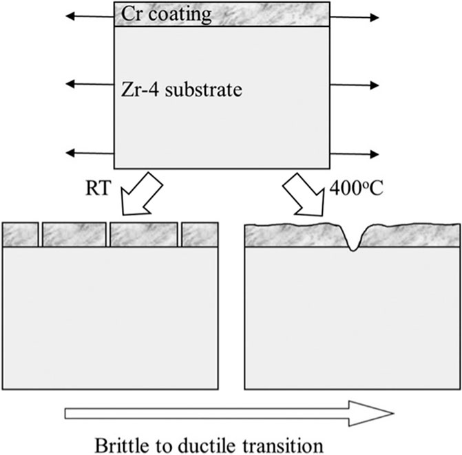
FIGURE 1. Schematic of the tensile fracture behaviors of Cr-coated Zr-4 at room temperature (RT) and 400°C, proceedings of ref (J. Jiang, Zhan, et al., 2021a) with copyright permission from the author. It is clearly shown that the fracture mode of the samples undergo a transaction from brittle to ductile.
As for the samples oxidized at high temperature (J. Jiang, Ma, and Wang, 2021c), different cracking phenomena are observed at various temperature levels. As shown in Figure 2, for samples oxidized at 900°C, the isometric crystals formed by recrystallization effectively hinder crack propagation, and the microcracks formed in the brittle Cr2O3 and ZrCr2 layers are difficult to propagate into the coating. In contrast, for samples oxidized at 1,000°C or above, large local thermal mismatch stress exists at the coating-substrate interface, and the Cr coating grains become coarser while the fracture toughness decreases. The oxygen enrichment in Zr-4 matrix promotes the formation of brittle α-Zr(O). The cracks in ZrCr2 layer penetrate the Cr coating and Zr matrix leading to samples failure. However, Jiang et al. did not give precise temperature levels for the two cracking mode transitions nor the effect of oxidation time.
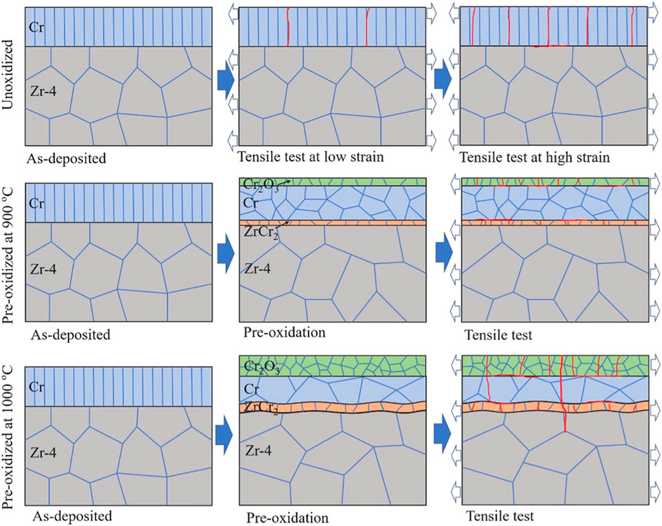
FIGURE 2. Cracking behaviors in unoxidized and preoxidized Cr-coated Zr-4 alloys at 900°C and 1,000°C, respectively, under tension, proceedings of ref (J. Jiang, Ma, and Wang, 2021b) with copyright permission from the author.
To systematically investigate the effect of coating thickness on crack propagation, Xu, Liu, and Wang (2021a) of Sun Yat-Sen University simulate the failure of Cr-coated samples in the presence of initial cracks at different thickness levels. The von Mises stress at Cr-Zr interface increases with coating thickness, implying the decreases of the critical crack length. The failure of coating is caused by stress concentration at the crack tips. Simulation results of radial crack propagation show that cracks propagate when the coating is very thick (greater than 50 µm). Wei et al. (2023) propose two failure modes for the Cr coating, namely: (1) the plastic zone of the crack tip reaches the coating-substrate interface; (2) the crack penetrates the coating and forms a coolant-substrate channel. By calculating the critical crack lengths for both modes, it is revealed that mode (2) predominates in cladding failures. Besides, with the increasing of the coating thickness, the critical crack length tends to be lower. That is, increasement of thickness promotes crack propagation. Wei et al. define a safety factor φ (the ratio of the critical crack length to the coating thickness) to evaluate the crack safety. The relationship between the safety factor φ and the coating thickness δ is shown in the following Figure 3.
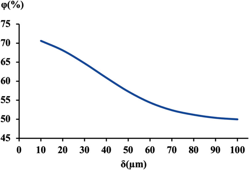
FIGURE 3. The relationship between percentage of safe crack
To compare the effect of coating thickness and crack length on crack propagation, Xu et al. (2021b) calculate the equivalent stress intensity factor for oblique cracks and find out that when the coating is relatively thick (>60 µm), the effect of coating thickness is limited. That is, the crack length has more critical effect on crack growth than the coating thickness.
So far, there is no confirming results from published literature on the effect of residual stress on cracking in Cr-coated Zr cladding, but some studies on other Cr-coated materials are reported. For instance, Pina et al. (1997) study the residual stress in Cr-coated Cu prepared by etching. The results show that three areas of different stress distribution exist inside the coating. The value of the residual stress at the surface of the coating is 800 ± 50 MPa. This region can be considered independent of the substrate and coating thickness. At the depth of about 20 μm, the residual stress tends to stabilize at a minimum value related to the coating thickness. Near the coating-substrate interface (depth of about 5 µm from substrate to the coating), there is a certain interfacial effect with a stress level of 270 ± 50 MPa, which relates to both the coating thickness and the type of substrate material. Different thickness and stress distribution levels may lead to various crack propagation behaviors within the coating.
It is concluded that crack initiation and propagation are influenced by many factors, such as temperature, the direction of external stress, coating thickness and residual stress within the coating. It should be noted that the results above do not fully consider the effect of stress in combination with corrosion and oxidation on the failure of the Cr coated Zr cladding. The coupling effect of stress along with other failure factors is suggested being studied in subsequent research.
2.1.2 Wear behavior
The fretting wear during reactor operation is mainly divided into two wear modes: grid-cladding mode and debris-cladding mode. The grid-cladding includes dimple-cladding wear and spring-cladding wear. Tests show that Cr coating can improve the wear resistance of the fuel rods.
Brachet et al. (J.-C. Brachet et al., 2019) use 6-μm-thick Cr-coated and uncoated samples on the “FROTTEAU 2” wear test rig to study the grid-cladding wear in a PWR environment. The uncoated samples have a cumulative wear depth of 65 μm–85 μm, while the Cr-coated samples have no significant scratches on the surface.
In order to accurately simulate the PWR water environment, Bischoff et al. (Jeremy Bischoff et al., 2018a) perform grid-cladding wear tests in the AURORE loop at Le Creusot Technical Center. The Cr-coated samples show nearly 98% reduction in wear volume compared to the uncoated samples, with no visible wear on the coating surface. In contrast, wears are observable at the dimples and gradually change to the shape of the cladding rods, which is consistent with the ideal configuration for wear. In the spring-cladding wear test, the Cr-coated samples also show negligible wear, while that of reference samples are severe. Cr-coated cladding reduces total wear by two orders of magnitude.
According to the GNF wear test report on ARMOR-coated Zircaloy-2 tubes (Lin et al., 2018), samples exhibit significantly less wear depth at the contact surfaces when subjected to abrasion and impingement at room temperature. However, variables such as debris size, contact force, and vibrational frequencies are not qualitatively examined in this test.
Therefore, Framatome (Delafoy et al., 2018) conducts another test using AFA 3G grid cell (Alloy 718 spring and dimple) and a AISI 316 wire brush, the results are shown in Figure 4. In the wear tests with the grids, the Cr-coated samples show smaller wear volume of 40 and 80 times in the dimple-cladding and spring-cladding tests respectively. In the wire brush tests simulating debris wear, the Cr-coated tubes show better wear resistance while the deformationof wire brush is evident in front of the samples. The Cr-coated samples show a lower wear volume by a factor of 4.5 after 100 h of testing compared to the uncoated sample stop at 23 h due to excessive wear. It can be concluded that under the same wear conditions, the Cr-coated sample will perform even better in the wear resistance test.
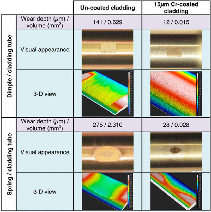
FIGURE 4. Results of grid-cladding wear tests of uncoated and Cr-coated cladding from ref (Delafoy et al., 2018).
J Bischoff et al. (2018b) observe wear on the samples in above tests. The size and depth of the notch on the Cr-coated samples decrease under the same test conditions. Despite the complete penetration of the coating, the wear rate of the Cr-coated samples remains low, which is probably due to the residual protection of the Cr coating in contact with the edges of the wire brush.
2.1.3 Fatigue behavior
As the reactor power fluctuates during normal operation, the cladding may be subjected to cyclic tension-compression loads, resulting in fatigue failure due to deformation in the axial direction. In addition, after fuel pellets contact with the claddings, the circumferential stress cycling may also lead to cladding fatigue. Therefore, this section summarizes research on the fatigue behavior of Cr-coated cladding.
Ševeček et al. (2018) examine the behavior of cold-sprayed (CS) Cr-coated samples in a four-point bending fatigue test in PWR water environment. Fatigue cracks appear earlier in the Cr-coated samples than the uncoated ones. The number of cracks in the samples increase rapidly as the test proceed, and ultimately the number of failure cycles of the Cr-coated samples are less than that of the uncoated samples (Figure 5). No cracks are shown on the top surface of the coating subjected to compressive stress, while numerous cracks are observed on the bottom surface due to tensile stress. Finally, the samples fail at the pinpoints. It is concluded that the failure of the Cr-coated samples may be due to two reasons. One is the high Young’s modulus of the Cr coating could cause high stress level during fatigue test. Meanwhile, the CS process may contribute to the additional compression stress within the coating.
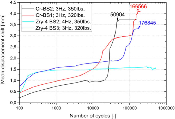
FIGURE 5. Mean displacement shift during the 4-point bending fatigue tests from ref (Ševeček et al., n.d.). Noted that the Cr-coated samples have lower plastic deformation and fail earlier than Zr-4.
In fact, some other studies (Price, Shipway, and McCartney, 2006; AL-Mangour et al., 2013; Sample et al., 2020) conclude that the shot peening effect introduced by CS can indeed cause stress concentration, early crack initiation and reduce the fatigue life of the coating samples.
X. Ma et al. (2021a) study the in-situ fatigue test at 400°C with SEM on Cr-coated standard tensile samples prepared by multi-arc ion plating under vacuum. The results show that the fatigue life of Cr-coated samples is higher than that of uncoated samples. In the test, the fatigue cracks in the Cr-coated samples are initiated within the coating and the Cr-Zr interface. The cracks are small and scattered. The samples show plastic deformation during fracture, and the bending of brittle interlayer is observed and confirmed by finite element analysis, indicating excellent Zr-Cr compatibility. The high fracture strength and toughness of Cr as well as the good compatibility with the Zr substrate, prevent the initiation of cracks in the Zr substrate and retard the propagation of the Cr-Zr interlayer cracks into the substrate.
The result of this study contradicts the study performed by Ševeček et al. (2018). However, a direct comparison is infeasible due to the different sample preparation methods, stress application methods and the test environments. In addition, no fatigue test on Cr-coated tubes is reported to date. In the future, research efforts can be intensified on the fatigue performance of Cr-coated cladding under normal PWR conditions, and the fatigue life of Cr-coated cladding can be predicted on the basis of the fatigue model (O’Donnell and Langer, 1964) of Zr cladding developed by O'Donnel and Langer.
2.2 Irradiation behavior
Because charged ions can interact with electrons and nuclei, their penetration depths are shallow. However, ion irradiation is easier to achieve and time-saving, thus it is widely used as an alternative in research.
The induction of light ions such as H+ and He2+ accumulate in the cladding and induce swelling of the materials, causing stress concentration and deterioration. As find by Huang et al. (2020), after He2+ irradiation, He bubbles are uniformly distributed in the Cr coating, with more in Cr grain boundaries than inside the grains. The size and concentration of He bubbles increase as the concentration of He2+ increases. Heavy ions have greater mass and more kinetic energy compared to light ions and penetrate deeper in the Cr coating, inducing more voids and damages. Kuprin et al. (2018) irradiate samples with 1.4 MeV Ar+ ions at 400°C and find that the Ar+ ion beam irradiation causes an increase in grain growth and anisotropy in the Cr coating. The size of voids in Cr coating increases with increasing of irradiation dose, while void density decreases. Sun et al. (2023) state that the size and density of dislocation rings increase with irradiation dose at 300°C, but the trend seems to be different at 400°C and 500°C. This may relate to the formation of dislocation networks. Regarding multiple ion beams, L. Jiang et al. (2020b) investigate that during the irradiation of Fe2+, the addition of He2+ promotes pore nucleation and enhances the ability of cavities to trap H+, while the addition of H+ would promotes cavity growth.
Compared to ion irradiation, neutrons only trigger collision effect when get close to the nuclei. This implies a larger mean free path and deeper penetration. Even for materials of certain thickness, neutron irradiation could trigger delocalization and transmutation. The primary knock-on atoms will interact with other atoms and trigger cascades of collision, resulting in Frenkel defects and gaseous phases. The aggregation of voids and gases will cause irradiation swelling and affect the performance of the cladding. Framatome (Bono et al., 2020) applies 2–8 µm Cr coating to M5 substrate samples and irradiate them in OSIRIS research reactor with a dose of 2dpa. After irradiation, the samples undergo the fixed-end Expansion Due to Compression (EDC) test at 350°C. The samples are able to withstand 2% circumferential strain without cracking. The minimum circumferential strain at fracture is 15% for irradiated samples and approximately 30% for unirradiated samples. This indicates that embrittlement occurs within the Cr-coated samples after irradiation. The surface of the irradiated samples observed by metallography and SEM are free of cracks and defects, and the interlayers are well bonded. This implies that even after irradiation, the Cr-coated samples still retain good integrity and adhesion.
The above tests indicate that the Cr-coated cladding undergoes embrittlement during neutron irradiation. Follow-up tests are required to quantitatively assess the effect of embrittlement on cladding properties.
3 Performance under LOCA
3.1 High-temperature oxidation behavior
The eutectic point of Cr-Zr is 1,332°C, which is higher than the Peak Cladding Temperature (1,204°C). To investigate the failure mode of the cladding at temperatures above the eutectic point, Jakub Krejčí et al. (2020) prepare 10.6 µm Cr-coated samples using unbalanced magnetron sputtering (UBM). The samples are quenched immediately after heating to 1,400°C in Ar environment. A molten layer of 50–100 µm is observed on the surface of the substrate with high Cr concentration (about 14%). Below the layer, the rest of the substrate remains unaffected. Another group of samples is first pre-oxidized in steam at 800°C for 12 min. The samples are then immediately transferred to 1,400°C steam environment for 2 min and quenched. The tests show that ZrO2 and α-Zr(O) layers appear on both the inner and outer surfaces, while the high Cr concentration zone (approximately 15%–16%) appears only in the center of the cladding.
Based on the comparison of the two tests, it can be concluded that in the environment above the eutectic point, oxygen accelerates Cr to transfer inward. Due to the excessive interaction with Cr and oxygen, the substrate depletion in steam environment is more severe. However, the heating steps are not exactly the same, which may be one of the reasons for the severe oxidation and melting phenomenon.
Although the temperature is lower than the eutectic temperature, many studies conclude that the coating also fails at 1,200°C, leading to oxidation of the underlying Zr substrate (Wagih et al., 2018; Yeom et al., 2019). Numerous experiments and investigations are supposed to be conducted to further understand the failure mechanism of high-temperature oxidation.
Han et al. (2019) perform high-temperature oxidation tests on coatings prepared by magnetron sputtering and find that the thickness of the Cr2O3 layer shows a trend of increasing and then decreasing after oxidized for 30–60 min. Therefore, they propose an oxidation mechanism based on the test results:
(1) At the beginning of oxidation, the Cr coating is completely oxidized to Cr2O3.
(2) When Cr2O3 layer is in contact with Zr, the Cr2O3 at the interface transfers to Cr by Zr, while a stable ZrO2 with lower Gibbs free energy forms.
The Cr2O3 reduction mechanism of this theory explains the phenomenon of Cr2O3 reduction during oxidation, but in the early stage of oxidation, the formation of a dense Cr2O3 layer on the outer surface can prevent oxygen from penetrating. In fact, the disappearance of Cr layer is not observed in the experiment. Besides, the theory cannot explains the kinetic of Zr transfers through ZrO2 to form an intermediate layer.
Based on the insufficiency of the model, J.-C. Brachet J. C. et al. (2020) perform experiments with longer oxidation times (>1,400 s) and propose a new presumption: Cr coating does not oxidize completely but still fails at high temperature (Figure 6.).
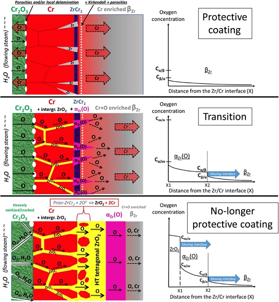
FIGURE 6. Schematic overview of the 3 stages of high temperature steam oxidation process of Cr-coated Zr, proceedings of ref (J.-C. Brachet J. C. et al., 2020).
In this theory, the failure of the Cr coating is divided into three main stages. In the first stage, the Cr layer remains dense, but the coating becomes thinner due to diffusion of Cr into the Zr substrate, and the interlayer thickens.
In the second stage, the weight gain of the sample steadily increases, but that of the Cr layer decreases as oxygen passes through the unoxidized Cr coating to form ZrO2 with Zr diffusing through Cr grain boundaries. The ZrO2 acts as a “bridge” for oxygen to pass through and continues to facilitate the inter-diffusion and oxidation of substrate. At this stage, the coating gradually loses its protectiveness. Moreover, Brachet et al. suggest that complete oxidation of Cr coatings does not exist due to the preference of oxygen with Zr, leaving residual Cr remain in the coating. Fazi et al. (2023) agree with this point and suggest that the rapid coarsening of Cr grains prepared by CS technology has a positive effect on the oxidation resistance of coatings. Liu et al. (2021) suggest that this phenomenon is only apparent in the late stage of high-temperature oxidation due to the limited distance of Zr diffusion in Cr.
And then there is the third stage: substrate oxidation. The residual Cr layer, which loses its protectiveness, adheres to the outer surface of the substrate. ZrO2 gradually forms below the layer, while oxygen continues to diffuse inward, reacting with the ZrCr2 to convert it into ZrO2 and Cr. Oddly, this conclusion is inconsistent with the results observed by Xiao et al. (2023). The thickness of the Cr-Zr interlayer increases linearly with oxidation time at 1,200°C, and the increasing rate is higher after 4 h of oxidation.
The mechanism of the changing in Cr-Zr diffusion layer thickness as well as its effect on macroscopic mechanical properties can be further investigated in the future.
Interestingly, Bell et al. (2022) perform EDS observations in the rupture area where the Cr-coated samples undergo large internal pressure. It is found that under Cr2O3 layer, the Cr layer remained is discontinuous. This suggests different stress contribution may cause diverse performances of the Cr coating oxidation.
During the oxidation, a continuous interdiffusion/intermetallic layer (31 at% Zr, 66 at% Cr, and 2.5 at% Fe) is observed (Wang et al., 2018; Wu et al., 2018; Yeom et al., 2019). It corresponds to the Cr2Zr or Zr(Fe, Cr)2 intermetallic Laves phases. Yeom et al. also find that the Cr-rich precipitates in the Zr substrate below the interface is formed due to the rapid Cr solid diffusion in β-Zr than in Zr(Fe, Cr)2. Kirkendall pores are detected around the interlayer due to faster element diffusion of Cr into Zr than that of Zr into Cr coating.
Yang et al. (2021) study the Cr-Zr interaction of Cr coated Zr cladding under inert gas environment in the temperature range from 1,100°C to 1,300°C. Samples are deposited by cold spray and magnetron sputtering respectively. The growth behavior of the Cr-Zr interlayer can be summarized as follows: Firstly, the interlayer is formed by mutual diffusion between the coating and substrate. The thickness of the interlayer continues to increase. At the same time, the Cr atoms in the Cr-Zr interlayer begin to diffuse and dissolve into the Zr matrix. The different diffusion coefficients of Cr in Zr(Fe,Cr)2 phase and Zr substrate causes the interlayer thickness to decrease. After that, the Cr-Zr interlayer gradually disappears. Additionally, they find out that the growth rate of the interlayer on cold sprayed samples is slightly larger than that on magnetron sputtered samples.
Nevertheless, Xiao et al. (2023) observe a rapid increasement of the thickness of Cr-Zr interlayer at 1,200°C in air atmosphere after 4 h oxidation. This indicates different oxidation atmospheres may lead to different growth behaviors.
Liu et al. (2021) investigate the effect of Sn on oxidation resistance of the coating. On the one hand, the affinity of Sn for oxygen is lower than that of Cr, so the segregation at the grain boundaries can prevent oxidation to a certain extent. On the other hand, the segregation leads to the aggregation of Kirkendall voids, which causes stress concentration and reduces the mechanical properties of the coating.
As mentioned in 2.1.1, the ZrCr2 interlayer cannot sustain tension or hinder the crack propagation. (J. Jiang, Ma, and Wang, 2021a). Thus, studies about diffusion barrier added between coating and substrate are reported (Sidelev et al., 2019; Michau, Ougier, and Maskrot, 2020) to restrain the interdiffusion at high temperature.
Besides, Liu et al. investigate the time of coating failure at 1,200°C and point out the start time (oxidation of about 30 min) and complete failure time (oxidation of about 90–120 min) (Liu et al., 2022). Assuming a buffer time of 30–90 min before complete failure can provide some guidance in predicting the life of the Cr coating during LOCA.
To investigate the best coating thickness with the oxidation resistance, Li et al. (2020) select 1, 2, 4, 6, and 8 μm thick coating samples for high-temperature oxidation tests at 1,200°C. The results show that the 6 and 8 μm Cr-coated samples exhibit the least weight gain. This implies the thicker Cr coatings have better oxidation resistance. On the other hand, defects such as voids and cracks are frequently observed in the over-thick coating samples. Therefore, from a comprehensive point of view, Li et al. select 6 μm as the ideal thickness of Cr coating.
A more precise test is performed by E. B. Kashkarov et al. (2020). The 4.5 μm-thick dense Cr coating is obtained by the multi-cathode magnetron sputtering, yet the 6 and 9 μm-thick columnar Cr coatings are obtained by hot target magnetron sputtering. The results show that the dense 4.5 μm-thick Cr coating with higher activation energy of 202 kJ/mol provides better oxidation resistance up to 1,100°C than thicker columnar coatings (177–183 kJ/mol). But at 1,200°C, only the 9 μm coating offers a longer diffusion path of O into the Zr substrate, and the fast interdiffusion at LOCA conditions requires thick coatings with high protection efficiency. Overall, a thicker coating of 9 μm is recommended.
In conclusion, to balance the economics with performance, a 6–9 μm coating might be an optimal coating thickness for commercial application, considering the studies from 2.1.1 section and above.
3.2 Quenching behavior and embrittlement
In the NRC Safety Standard for Reactor Emergency Core Cooling Systems (ECCS) (USNRC. Regulatory Guide 1.223-Determining Post-Quench Ductility, Washington. D.C., USA, 2018), the upper limit of the equivalent cladding reacted (ECR) is set at 17%. The ECR limit can be calculated through cladding weight-gain method and the oxidation kinetics equations - the Baker-Just (BJ) relation (Baker et al., 1961) and the Cathcart-Pawel (CP) relation (Cathcart et al., 1977). Cladding ductility are evaluated experimentally using the RCT ring compression test (Hobson and Rittenhouse, 1972). It should be clarified that the standard above applies to Zr alloy cladding, while that of Cr-coated cladding has not yet been developed. Therefore, in order to confirm whether the three ECR calculation methods and the 17% threshold are applicable to Cr-coated cladding, the relationship between the values derived from the three methods and the brittleness of coated samples will be analyzed in the following section.
The RCT test performed by J Krejčí et al. (2018) of the two thresholds of ECR = 17% and RCT = 2% are marked with red and black dashed lines respectively in Figure 7. It can be observed from both Figures 7A, B that for Zr samples, the ECR values corresponding to the brittle samples are less than 17%. Some of the samples with ECR>17% still show plasticity. This indicates that ECR = 17% is a conservative prediction for embrittlement of the Zr cladding. In contrast, for the Cr-coated samples, the ECR calculation using the CP equation (Figure 7A) shows that the 30 μm Cr coating significantly increases the threshold of embrittlement for Cr cladding. Some samples show embrittlement with ECR values much higher than 17%. However, when ECR is calculated by weight gain (Figure 7B), several coated samples show embrittlement even if ECR<5%. During the test, in fact, the weight of the Cr coated samples decreases in the pre-oxidation period and increases only after the Zr substrate was oxidized. This may be the reason for the discrepancy between the ECR values calculated by the weight gain method and the CP relation.
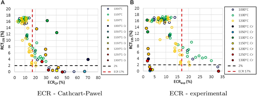
FIGURE 7. Residual ductility measured by RCT at 135°C in relation with (A) CP-ECR and (B) experimental (deduced from weight gain measurements)-ECR from ref (J Krejčí et al., n.d.).
Similarly, J. C. Brachet J.-C. et al. (2020) perform one-sided steam oxidation on 12–15 μm thick Cr-coated samples at 1,200°C, shown in Figure 8. The ECR threshold of brittleness calculated by BJ relation is approximately 50%. Meanwhile, the ECR value calculated by weight gain does not exceed 5%. This again proves the ECR values vary from weight gain method and oxidation kinetics relationship, and the 17% threshold is no longer consistent among the three methods mentioned above. Therefore, the calculation of ECR for Cr-coated cladding must be re-evaluated, and its threshold as well.
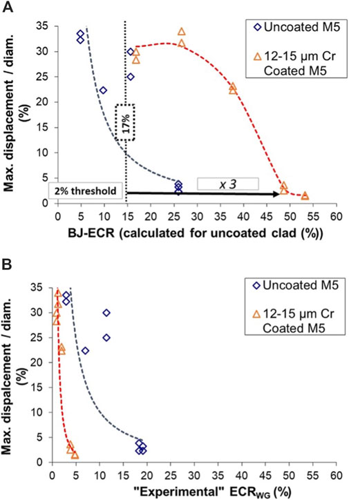
FIGURE 8. Residual ductility measured RCT at 135°C in relation with (A) BJ-ECR and (B) experimental (deduced from weight gain measurements) ECR from ref (J. C. Brachet J.-C. et al., 2020)
Moreover, J.-C. Brachet J. C. et al. (2020) investigate the mechanism of embrittlement after quenching. Initially, a dense oxide layer forms on the surface of the Cr coating, which prevents the Zr substrate from oxidizing. The diffusion of Cr into the substrate at this time increases the ductility of the sample to a small extent. As the oxidation time extends, the protective layer gradually fails and oxygen diffuses into the substrate to form α-Zr(O), increasing the brittleness of the cladding. This is similar to the mechanism derived in Section 3.1.
In addition, the ECR values calculated by the BJ equation and corresponding oxidation conditions are given by Brachet et al. as shown in Table 1.
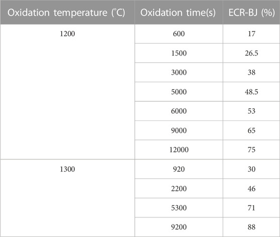
TABLE 1. Oxidation conditions, corresponding ECR-BJ values measured by Brachet et al., proceeding from ref (J.-C. Brachet J. C. et al., 2020).
Yook et al. (2022) subject unsealed Cr-coated and uncoated tube samples to double-sided oxidation in steam environment at 1,204°C, followed by cooling to 800°C before quenching, and calculate the ECR values of the samples using weight gain method. Microstructural studies show that the brittleness of the Cr-coated samples correlates with the α-Zr(O) in the substrate. Due to the resistance of the Cr coating, no significant oxidation is observed on the outer surface of the Cr-coated samples after quenching, but the concentration of brittle phase is observed on the inner surface of uncoated samples. The thickness of the brittle phase is higher than the that of the uncoated samples. Therefore, Yook et al. conclude that the evaluation of the ductility of Cr-coated samples using RCT may be inaccurate because cracks will first appear on the inner walls of the samples.
The results of the weight gain method show lower ECR values and better ductility with same oxidation time for the coated cladding. Since the samples take longer to reach the ECR value, the coated undergo more oxidation. This indicates the ECR limit calculated by the weight gain method is lower and the time for Cr-coated samples to reach the limit is longer. The corresponding ECR values with different oxidation time are given in Table 2.
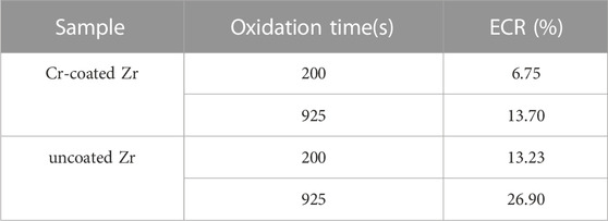
TABLE 2. Oxidation time, corresponding experimental ECR (measured by weight gain) values, proceeding from ref. Yook et al. (202).
In addition, Yook et al. believe that the weight gain method for Zr cladding is informative for setting ECR threshold for Cr-coated cladding. They suggest that the ECR threshold to be set at 13.8% for double-sided oxidation at 1,204°C. In that case, the Cr-coated cladding could save for 10 more minutes than the Zr cladding in accident response.
However, there are some views on new ductility evaluation criteria besides the ECR value. For example, Jakub Krejčí et al. (2020) investigate the relationship between ductility, the internal oxygen content of the samples (which varies very little within one sample) and the hardness of β-Zr, as shown in Figure 9. 0.4 wt% oxygen content and HVβ-Zr 0.1 = 350 can be set as new evaluation criteria.
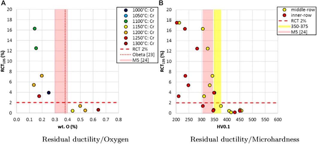
FIGURE 9. Results of RCT residual ductility at 135°C in relation with (A) internal oxygen content, which varies very little within one sample, and (B) microhardness of β-Zr from ref (Jakub Krejčí et al., 2020).
At present, the evaluation criteria for the ductility of coatings after quenching are divided into two, one is to follow the ECR value of oxidation, which can be obtained by evaluating the calculation results of the BJ or CP relations, or modifying the 17% threshold value derived from the weight gain method; the other way is to use new physical properties (such as oxygen content and micro-zone hardness mentioned above) to characterize the ductility. Both ways need to be further investigated.
3.3 Creep behavior
During LOCA, the inner pressure of cladding ranging between 1 and 8 MPa(Chalupová et al., 2019). The failure of Cr-coated cladding caused by creep is also studied in recent studies.
Brachet et al. report (J. C. Brachet et al., 2016) isothermal creep tests with constant internal pressure. The results show that the Cr coating enhance the overall thermomechanical properties and have a positive effect on prolonging the rupture time in the temperature range of 600°C–1,000°C. In the follow-up test (J. C. Brachet et al., 2017), they report a significant decrease in circumferential elongation for Cr-coated M5™, demonstrating the ability of the Cr coating to enhance the creep resistance of the cladding.
Adéla Chalupová et al. (Chalupová et al., 2019) measure the deformation of creep burst specimens at 800°C in the position of 20 mm from the burst-opening. The creep rate is determined by the occurrence of uniform deformation at the location. The results show that the creep rate of Cr-coated samples is lower for circumferential strain greater than 40 MPa. In addition, the higher the circumferential strain, the greater the discrepancy in creep rate between Cr-coated and uncoated specimens.
The current general acknowledgement is that Cr coating enhances the creep resistance of Zr cladding. However, quantitative studies on creep testing have not been reported yet and need further studies.
3.4 Balloon and burst behavior
The general patterns in current burst tests (Kim et al., 2015; Delafoy et al., 2018; J. C; Brachet et al., 2017; Dumerval et al., 2020) is that the Cr-coated cladding can improve burst resistance in following aspects: higher burst temperature, lower circumferential strain in the burst region, and smaller burst openings. The results are summarized in Figure 10 as general results.
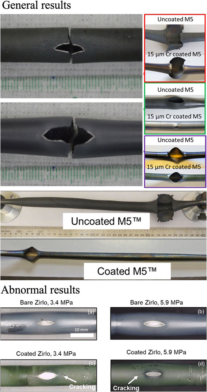
FIGURE 10. General results of general cladding balloon and burst tests (Park et al., 2016; J. C; Brachet et al., 2017; Dumerval et al., n.d.) and the abnormal results (Bell et al., 2022).
Kim et al. (2015) attribute the improved burst resistance mainly to the Cr coating which increases the overall strength of the cladding. To investigate the ductility of the burst samples, Park et al. (2016) perform four-point bending tests. It is stated that the maximum load on the burst coating sample is greater. This is due to the retardation of oxidation in Zr substrate, as well as the lower circumferential strain and thicker wall on the opposite side of the burst opening.
However, some test results deviate from the general rules:
The tests performed by Bell et al. (2022) use pulsed DC magnetron sputtering to prepare coated samples of 4 µm thickness, shown in Figure 10 abnormal results. The pattern is basically the same at high pressure, but the burst temperature of the Cr-coated sample is lower at low pressure level, and no significant effect of the coating on radial strain is found. The oxidation on the opposite side of the burst opening proves that the Cr coating has some protective effect on the substrate, but in the high strain region near the opening, the coating loses its protectiveness due to the penetrating cracks, and a 50–60 µm thick ZrO2 layer appears on both inner and outer layer of the samples.
To predict the balloon-burst behavior, Z. Ma et al. (2021b) perform numerical simulations using ABAQUS software. They conclude that thicker coatings may slightly increase the burst strain rate, but overall, the effect of coating thickness on balloon and burst temperature is not significant, which somewhat contradicts the experimental results of Bell et al. (2022). Since the thickness data of the coating samples cited by Ma et al. and shown in Figure 10 “General results” are greater than 10 μm, it is likely that the change in burst size will show a deviated trend for thinner coatings. In addition, Ma et al. conclude the 100% and 85% of the Cr fracture strength at heating rates of 5 K/s and 10 K/s respectively, to be used as new burst criteria for Cr-coated cladding, and strain rates of 0.23/s and 0.07/s as plastic instability criteria for Cr-coated cladding.
Shahin et al. (2022) perform test on 20–30 µm thick coated samples prepared by CS and observe that the crack lengths in Cr-coated and uncoated samples are close, with slightly longer cracks in the Cr-coated samples, but no detailed schematic diagram is provided in their paper.
4 Prospect of future works
For now, Westinghouse, General Electric, KAERI, CEA, AREVA (Framatome), and NPIC all focus on the development and commercial application of Cr-coated Zr alloy cladding (Jeremy Bischoff et al., 2018a; Chen, Wang, and Zhang, 2020; Ko et al., 2022). The Cr coating cladding already meets the expectation of suppressing the reaction with steam and hydrogen generation (Kim et al., 2017; Kurt A. Terrani, 2018). Apart from that, according to the research, Cr-coated cladding also outperforms the original Zr alloy cladding in terms of improving wear resistance, creep resistance, ductility after quenching, and reduce the size of burst opening. However, current studies on several properties and mechanism are still insufficient and need further research:
(1) Fatigue Behavior
At present, the number of studies on Cr-coated cladding is relatively small, and most are performed on standard samples other than tubes. The coating process, coating thickness and test environment are not uniform either. Direct comparison is not possible for the present cases, and the experimental conclusions are not instructive for the application of Cr-coated tubular claddings. Based on the fatigue curve of Zr cladding, the characteristics can be further optimized to derive the universal law for Cr-coated claddings.
(2) Coupling Effect of Stress and Oxidation
Previous studies mostly conducted high-temperature oxidation tests on samples without the presence of stress, which is implausible under the LOCA. Therefore, the coupling effect of stress and oxidation on crack initiation and propagation in the coating needs to be analyzed in the following study.
(3) Embrittlement Safety Limits After Quenching
The current standard follows the traditional method of evaluating the embrittlement of uncoated Zr alloy claddings. That is, the ECR value of 17% based on oxidation weight gain is used as the quench embrittlement threshold. However, tests have shown that this threshold is no longer applicable to Cr-coated claddings. As an alternative, one approach is to use the weight gain method, BJ or CP relationships to define a new ECR limit. The other is to define a new limit based on the oxidation behavior and the associated physical properties. Both approaches are in need of further investigation.
(4) Prediction of Coating Life Under LOCA Conditions
The duration of effective protection provided by Cr coatings under accident conditions (i.e., coating life) is an important parameter for evaluating coating quality. Existing high-temperature oxidation studies have shown that even if the coating remains, it may not provide effective protection. This indicates that the change in coating thickness cannot simply be used to predict coating life. In this regard, no credible calculation and prediction model has been established yet. A model based on exposure temperature, coating thickness, and elemental diffusion may be proposed in the future to accurately assess coating life.
Author contributions
Investigation, ZL and HC; Data curation, ZL; Formal analysis, ZL; Visualization, ZL; Writing—original draft preparation, ZL; Writing—review and editing, ZL and XW; Supervision, XW, RZ, HC, TW, LY, and PW; Project administration, RZ. All authors contributed to the article and approved the submitted version.
Acknowledgments
Deep and sincere thanks to Dai M. for the 6 years of companionship and to A. Cao for the warm emotional support.
Conflict of interest
The authors declare that the research was conducted in the absence of any commercial or financial relationships that could be construed as a potential conflict of interest.
Publisher’s note
All claims expressed in this article are solely those of the authors and do not necessarily represent those of their affiliated organizations, or those of the publisher, the editors and the reviewers. Any product that may be evaluated in this article, or claim that may be made by its manufacturer, is not guaranteed or endorsed by the publisher.
References
Al-Mangour, B., Dallala, R., Zhim, F., Mongrain, R., and Yue, S. (2013). Fatigue behavior of annealed cold-sprayed 316L stainless steel coating for biomedical applications. Mater. Lett. 91, 352–355. doi:10.1016/j.matlet.2012.10.030
Arias, D., and Abriata, J. P. (1986). The Cr−Zr (Chromium-Zirconium) system. Bull. Alloy Phase Diagrams 7 (3), 237–244. doi:10.1007/BF02868997
Aydogan, E., Weaver, J. S., Maloy, S. A., El-Atwani, O., Wang, Y. Q., and Mara, N. A. (2018). Microstructure and mechanical properties of FeCrAl alloys under heavy ion irradiations. J. Nucl. Mater. 503, 250–262. doi:10.1016/j.jnucmat.2018.03.002
Baker, L., Warchal, R. L., Vogel, R. C., and Kilpatrick, M. (1961). ANL-6257. Argonne, IL United States: Argonne National Lab. Studies of metal-water reactions at high temperatures. Iii. Experimental and theoretical studies of the zirconium-water reaction. doi:10.2172/4019606
Bell, S. B., Graening, T., Evans, A., Kelly, P., Pint, B. A., and Kane, K. A. (2022). Burst and oxidation behavior of Cr-coated zirlo during simulated LOCA testing. J. Nucl. Mater. 564, 153679. doi:10.1016/j.jnucmat.2022.153679
Bischoff, J., Delafoy, C., Chaari, N., Vauglin, C., Buchanan, K., Barberis, P., et al. “Cr-coated cladding development at framatome,” in Proceedings of the Topfuel 2018, Prague, Czech Republic, September 2018a.
Bischoff, J., Delafoy, C., Vauglin, C., Barberis, P., Roubeyrie, C., Perche, D., et al. (2018b). AREVA NP’s enhanced accident-tolerant fuel developments: Focus on Cr-coated M5 cladding. Nucl. Eng. Technol. 50 (2), 223–228. doi:10.1016/j.net.2017.12.004
Bono, M., Pham, T.-H., Courcelle, A., Mallet, C., Pegaitaz, J., Sibille, Y., et al. (2020). Mechanical testing of irradiated ATF chromium-coated Zr-based. Claddings 2. doi:10.13140/RG.2.2.34085.52964
Brachet, J.-C., Idarraga-Trujillo, I., Flem, M. L., Saux, M. L., Vandenberghe, V., Urvoy, S., et al. (2019). Early studies on Cr-coated zircaloy-4 as enhanced accident tolerant nuclear fuel claddings for light water reactors. J. Nucl. Mater. 517, 268–285. doi:10.1016/j.jnucmat.2019.02.018
Brachet, J.-C., Rouesne, E., Ribis, J., Guilbert, T., Urvoy, S., Nony, G., et al. (2020b). High temperature steam oxidation of chromium-coated zirconium-based alloys: Kinetics and process. Corros. Sci. 167, 108537. doi:10.1016/j.corsci.2020.108537
Brachet, J. C., Dumerval, M., Lezaud-Chaillioux, V., Saux, M. L., Rouesne, E., Hamon, D., et al. “Behavior of chromium coated M5TM claddings under LOCA conditions,” in Proceedings of the 2017 Water Reactor Fuel Performance Meeting, Jeju Island, Korea, September 2017.
Brachet, J. C., Houmaire, Q., Lomello, F., Schuster, F., and Monsifrot, E. “Behavior under LOCA conditions of enhanced accident tolerant chromium coated zircaloy-4 claddings,” in Proceedings of the Top Fuel, La Grange Park, IL, USA, September 2016.
Brachet, J. C., Saux, M. L., Bischoff, J., Palancher, H., Chosson, R., Pouillier, E., et al. (2020a). Evaluation of equivalent cladding reacted parameters of Cr-coated claddings oxidized in steam at 1200°C in relation with oxygen diffusion/partitioning and post-quench ductility. J. Nucl. Mater. 533, 152106. doi:10.1016/j.jnucmat.2020.152106
Cathcart, J. V., Pawel, R. E., McKee, R. A., Druschel, R. E., Yurek, G. J., Campbell, J. J., et al. (1977). ORNL/NUREG-17, 7317596. Oak Ridge, TN, (United States: Oak Ridge National Lab. Zirconium metal-water oxidation kinetics. IV. Reaction rate studies. doi:10.2172/7317596
Chalupová, A., Krejčí, J., Cvrček, L., Ševeček, M., Rozkošný, V., Přibyl, A., et al. (2019). Coated cladding behavior during high-temperature transients. Acta Polytech. CTU Proc. 24. doi:10.14311/APP.2019.24.0009
Chen, H., Wang, X., and Zhang, R. (2020). Application and development progress of Cr-based surface coatings in nuclear fuel element: I. Selection, preparation, and characteristics of coating materials. Coatings 10 (9), 808. doi:10.3390/coatings10090808
Delafoy, C., Bischoff, J., Larocque, J., Attal, P., Gerken, L., and Nimishakavi, K. (2018). Benefits of framatome’s E-ATF evolutionary solution: Cr-coated cladding with Cr2O3-doped fuel. Brussels, Belgium: European Nuclear Society.
Dumerval, M., Houmaire, Q., Brachet, J. C., Palancher, H., Bischoff, J., and Pouillier, E. “Behavior of chromium coated M5 claddings upon thermal ramp tests under internal pressure (Loss-of-Coolant accident conditions,” in Proceedings of the Topfuel 2018, Prague, Czech Republic, September 2020.
Fazi, A., Sattari, M., Stiller, K., Andrén, H.-O., and Thuvander, M. (2023). Performance and evolution of cold spray Cr-coated optimized ZIRLOTM claddings under simulated loss-of-coolant accident conditions. J. Nucl. Mater. 576, 154268. doi:10.1016/j.jnucmat.2023.154268
Field, K. G., Briggs, S. A., Sridharan, K., Howard, R. H., and Yamamoto, Y. (2017). Mechanical properties of neutron-irradiated model and commercial FeCrAl alloys. J. Nucl. Mater. 489, 118–128. doi:10.1016/j.jnucmat.2017.03.038
Field, K. G., Hu, X., Littrell, K. C., Yamamoto, Y., and Snead, L. L. (2015). Radiation tolerance of neutron-irradiated model Fe–Cr–Al alloys. J. Nucl. Mater. 465, 746–755. doi:10.1016/j.jnucmat.2015.06.023
George, N. M., Terrani, K., Powers, J., Worrall, A., and Maldonado, I. (2015). Neutronic analysis of candidate accident-tolerant cladding concepts in pressurized water reactors. Ann. Nucl. Energy 75, 703–712. doi:10.1016/j.anucene.2014.09.005
Gupta, V. K., Larsen, M., and Rebak, R. B. (2018). Utilizing FeCrAl oxidation resistance properties in water, air and steam for accident tolerant fuel cladding. ECS Trans. 85 (2), 3–12. doi:10.1149/08502.0003ecst
Han, X., Xue, J., Peng, S., and Zhang, H. (2019). An interesting oxidation phenomenon of Cr coatings on zry-4 substrates in high temperature steam environment. Corros. Sci. 156, 117–124. doi:10.1016/j.corsci.2019.05.017
Hobson, D. O., and Rittenhouse, P. L. (1972). Embrittlement of zircaloy-clad fuel rods by steam during LOCA transients. ORNL--4758, 4670175. doi:10.2172/4670175
Huang, M., Li, Y., Ran, G., Yang, Z., and Wang, P. (2020). Cr-coated Zr-4 alloy prepared by electroplating and its in situ He+ irradiation behavior. J. Nucl. Mater. 538, 152240. doi:10.1016/j.jnucmat.2020.152240
Jiang, J., Ma, X., and Wang, B. (2021a). Positive or negative role of preoxidation in the crack arresting of Cr coating for accident tolerant fuel cladding. Corros. Sci. 193, 109870. doi:10.1016/j.corsci.2021.109870
Jiang, J., Zhai, H., Du, M., Wang, D., Pei, X., Ma, X., et al. (2021b). Temperature-dependent deformation and cracking behavior in Cr coating for accident tolerant fuel cladding: An in situ SEM study. Surf. Coatings Technol. 427, 127815. doi:10.1016/j.surfcoat.2021.127815
Jiang, J., Zhai, H., Gong, P., Zhang, W., He, X., Ma, X., et al. (2020a). In-situ study on the tensile behavior of Cr-coated Zircaloy for accident tolerant fuel claddings. Surf. Coatings Technol. 394, 125747. doi:10.1016/j.surfcoat.2020.125747
Jiang, J., Zhan, D., Lv, J., Ma, X., He, X., Wang, D., et al. (2021c). Comparative study on the tensile cracking behavior of CrN and Cr coatings for accident-tolerant fuel claddings. Surf. Coatings Technol. 409, 126812. doi:10.1016/j.surfcoat.2020.126812
Jiang, L., Peng, Q., Xiu, P., Yan, Y., Jiao, Z., Lu, C., et al. (2020b). Elucidating He-H assisted cavity evolution in alpha Cr under multiple ion beam irradiation. Scr. Mater. 187, 291–295. doi:10.1016/j.scriptamat.2020.06.031
Kim, H.-G., Kim, I.-H., Jung, Y.-I., Park, D.-J., Park, J.-Y., and Koo, Y.-H. (2015). Adhesion property and high-temperature oxidation behavior of Cr-coated zircaloy-4 cladding tube prepared by 3D laser coating. J. Nucl. Mater. 465, 531–539. doi:10.1016/j.jnucmat.2015.06.030
Kam, D. H., Lee, J. H., Lee, T., and Jeong, Y. H. (2015). Critical heat flux for SiC- and Cr-coated plates under atmospheric condition. Ann. Nucl. Energy 76, 335–342. doi:10.1016/j.anucene.2014.09.046
Kashkarov, E., Afornu, B., Sidelev, D., Krinitcyn, M., Gouws, V., and Lider, A. (2021). Recent advances in protective coatings for accident tolerant Zr-based fuel claddings. Coatings 11 (5), 557. doi:10.3390/coatings11050557
Kashkarov, E. B., Sidelev, D. V., Syrtanov, M. S., Tang, C., and Steinbrück, M. (2020). Oxidation kinetics of Cr-coated zirconium alloy: Effect of coating thickness and microstructure. Corros. Sci. 175, 108883. doi:10.1016/j.corsci.2020.108883
Kim, H.-G., Kim, I.-H., Jung, Y.-I., Park, D.-J., Park, J.-H., Yang, J.-H., et al. “Progress of surface modified Zr cladding development for ATF at KAERI,” in Proceedings of the 2017 Water Reactor Fuel Performance Meeting, Jeju Island, Korea, September 2017.
Ko, J., Kim, J. W., Min, H. W., Kim, Y., and Yoon, Y. S. (2022). Review of manufacturing technologies for coated accident tolerant fuel cladding. J. Nucl. Mater. 561, 153562. doi:10.1016/j.jnucmat.2022.153562
Krejčí, J., Ševeček, M., Kabátová, J., Manoch, F. J., Kočí, L., Cvrček, J. M., et al. “Experimental behavior of chromium-based coatings,” in Proceedings of the Topfuel 2018, Prague, Czech Republic, September 2018.
Krejčí, J., Kabátová, J., Manoch, F., Kočí, J., Cvrček, L., Málek, J. S. K., et al. (2020). Development and testing of multicomponent fuel cladding with enhanced accidental performance. Nucl. Eng. Technol. 52 (3), 597–609. doi:10.1016/j.net.2019.08.015
Kuprin, A. S., Belous, V. A., Voyevodin, V. N., Vasilenko, R. L., Ovcharenko, V. D., Tolstolutskaya, G. D., et al. (2018). Irradiation resistance of vacuum arc chromium coatings for zirconium alloy fuel claddings. J. Nucl. Mater. 510, 163–167. doi:10.1016/j.jnucmat.2018.07.063
Li, G., Liu, Y., Zhang, Y., Li, H., Wang, X., Zheng, M., et al. (2020). High temperature anti-oxidation behavior and mechanical property of radio frequency magnetron sputtered Cr coating. Metals 10 (11), 1509. doi:10.3390/met10111509
Lin, Y. P., Fawcett, R. M., Desilva, S. S., Lutz, D. R., Yilmaz, M. O., Davis, P., et al. . Brussels, Belgium: European Nuclear Society.Path towards industrialization of enhanced accident tolerant fuel
Liu, J., Cui, Z., Hao, Z., Ma, D., Lu, J., Cui, Y., et al. (2021). Steam oxidation of Cr-coated Sn-containing Zircaloy solid rod at 1000 °C. Corros. Sci. 190, 109682. doi:10.1016/j.corsci.2021.109682
Liu, J., Steinbrück, M., Große, M., Stegmaier, U., Tang, C., Yun, D., et al. (2022). Systematic investigations on the coating degradation mechanism during the steam oxidation of Cr-coated zry-4 at 1200 °C. Corros. Sci. 202, 110310. doi:10.1016/j.corsci.2022.110310
Ma, X., Zhai, H., Meng, F., Jiang, J., He, X., Hu, Y., et al. (2021a). Benefit or harm of accident tolerant coatings on the low-cycle fatigue properties of Zr-4 cladding alloy: In-situ studies at 400°C. J. Nucl. Mater. 545, 152651. doi:10.1016/j.jnucmat.2020.152651
Ma, Z., Shirvan, K., Wu, Y., and Su, G. H. (2021b). Numerical investigation of ballooning and burst for chromium coated Zircaloy cladding. Nucl. Eng. Des. 383, 111420. doi:10.1016/j.nucengdes.2021.111420
Michau, A., Ougier, M., and Maskrot, H. “Interlayers for Cr-coated,” in Proceedings of the Nuclear Fuel Claddings, October 2020. doi:10.13140/RG.2.2.11760.69123
Nguyen, D. V., Le Saux, M., Gélébart, L., Brachet, J.-C., Bonthonneau, J.-P., Courcelle, A., et al. (2022). Mechanical behavior of a chromium coating on a zirconium alloy substrate at room temperature. J. Nucl. Mater. 558, 153332. doi:10.1016/j.jnucmat.2021.153332
O’Donnell, W. J., and Langer, B. F. (1964). Fatigue design basis for Zircaloy components. Nucl. Sci. Eng. 20 (1), 1–12. doi:10.13182/NSE64-A19269
Opila, E. J. (2004). Volatility of common protective oxides in high-temperature water vapor: Current understanding and unanswered questions. Mater. Sci. Forum 461–464, 765–774. doi:10.4028/www.scientific.net/MSF.461-464.765
Park, D. J., Jung, Y. I., Kim, H. G., Park, J. Y., and Koo, Y. H. (2014). Oxidation behavior of silicon carbide at 1200°C in both air and water–vapor-rich environments. Corros. Sci. 88, 416–422. doi:10.1016/j.corsci.2014.07.052
Park, D. J., Kim, H. G., Jung, Y. I., Park, J. H., Yang, J. H., and Koo, Y. H. (2016). Behavior of an improved Zr fuel cladding with oxidation resistant coating under loss-of-coolant accident conditions. J. Nucl. Mater. 482, 75–82. doi:10.1016/j.jnucmat.2016.10.021
Park, D. J., Kim, H. G., Park, J. Y., Jung, Y. I., Park, J. H., and Koo, Y. H. (2015). A study of the oxidation of FeCrAl alloy in pressurized water and high-temperature steam environment. Corros. Sci. 94, 459–465. doi:10.1016/j.corsci.2015.02.027
Pina, J., Dias, A., François, M., and Lebrun, J. L. (1997). Residual stresses and crystallographic texture in hard-chromium electroplated coatings. Surf. Coatings Technol. 96 (2–3), 148–162. doi:10.1016/S0257-8972(97)00075-3
Pint, B. A., Terrani, K. A., and Rebak, R. B. “Steam oxidation behavior of FeCrAl cladding,” in Proceedings of the 18th International Conference on Environmental Degradation of Materials in Nuclear Power Systems – Water Reactors, October 2019. doi:10.1007/978-3-030-04639-2_96
Price, T. S., Shipway, P. H., and McCartney, D. G. (2006). Effect of cold spray deposition of a titanium coating on fatigue behavior of a titanium alloy. J. Therm. Spray Technol. 15 (4), 507–512. doi:10.1361/105996306X147108
Rebak, R. B. (2015). Alloy selection for accident tolerant fuel cladding in commercial light water reactors. Metallurgical Mater. Trans. E 2 (4), 197–207. doi:10.1007/s40553-015-0057-6
Sample, C. M., Champagne, V. K., Nardi, A. T., and Lados, D. A. (2020). Factors governing static properties and fatigue, fatigue crack growth, and fracture mechanisms in cold spray alloys and coatings/repairs: A review. Addit. Manuf. 36, 101371. doi:10.1016/j.addma.2020.101371
Ševeček, M., Krejčí, J., Shahin, M. H., Petrik, J., Ballinger, R. G., and Shirvan, K. “Fatigue behavior of cold spray-coated accident tolerant cladding,” in Proceedings of the TopFuel 2018, Prague, Czech Republic, October 2018.
Shahin, M., Petrik, J., Seshadri, A., Phillips, B., and Shirvan, K. (2022). Experimental investigation of cold-spray chromium cladding. Brussels, Belgium: European Nuclear Society.
Sidelev, D. V., Kashkarov, E. B., Syrtanov, M. S., and Krivobokov, V. P. (2019). Nickel-chromium (Ni–Cr) coatings deposited by magnetron sputtering for accident tolerant nuclear fuel claddings. Surf. Coatings Technol. 369, 69–78. doi:10.1016/j.surfcoat.2019.04.057
Snead, L. L., Nozawa, T., Katoh, Y., Byun, T.-S., Kondo, S., and Petti, D. A. (2007). Handbook of SiC properties for fuel performance modeling. J. Nucl. Mater. 371 (1–3), 329–377. doi:10.1016/j.jnucmat.2007.05.016
Sun, Z., Li, Y., Qiu, X., Sun, D., Du, P., Zhang, R., et al. (2023). An in-situ TEM investigation of microstructure evolution in Cr-coated zirconium alloy under heavy ion irradiation: Simultaneous evolution of both Cr coating and Zr-4 matrix. Nucl. Instrum. Methods Phys. Res. Sect. B Beam Interact. Mater. Atoms 536, 97–103. doi:10.1016/j.nimb.2023.01.002
Terrani, K. A., Pint, B. A., Kim, Y.-J., Unocic, K. A., Yang, Y., Silva, C. M., et al. (2016). Uniform corrosion of FeCrAl alloys in LWR coolant environments. J. Nucl. Mater. 479, 36–47. doi:10.1016/j.jnucmat.2016.06.047
Terrani, K. A., Zinkle, S. J., and Snead, L. L. (2014). Advanced oxidation-resistant iron-based alloys for LWR fuel cladding. J. Nucl. Mater. 448 (1–3), 420–435. doi:10.1016/j.jnucmat.2013.06.041
Terrani, Kurt A. (2018). Accident tolerant fuel cladding development: Promise, status, and challenges. J. Nucl. Mater. 501, 13–30. doi:10.1016/j.jnucmat.2017.12.043
Terrani, Kurt A., Parish, C. M., Shin, D., and Pint, B. A. (2013). Protection of zirconium by alumina- and chromia-forming iron alloys under high-temperature steam exposure. J. Nucl. Mater. 438 (1–3), 64–71. doi:10.1016/j.jnucmat.2013.03.006
Umretiya, R. V., Elward, B., Lee, D., Anderson, M., Rebak, R. B., and Rojas, J. V. (2020). Mechanical and chemical properties of PVD and cold spray Cr-coatings on zircaloy-4. J. Nucl. Mater. 541, 152420. doi:10.1016/j.jnucmat.2020.152420
Wagih, M., Spencer, B., Hales, J., and Shirvan, K. (2018). Fuel performance of chromium-coated zirconium alloy and silicon carbide accident tolerant fuel claddings. Ann. Nucl. Energy 120, 304–318. doi:10.1016/j.anucene.2018.06.001
Wang, Y., Zhou, W., Wen, Q., Ruan, X., Luo, F., Bai, G., et al. (2018). Behavior of plasma sprayed Cr coatings and FeCrAl coatings on Zr fuel cladding under loss-of-coolant accident conditions. Surf. Coatings Technol. 344, 141–148. doi:10.1016/j.surfcoat.2018.03.016
Wei, J., Xu, Z., Li, J., Liu, Y., and Wang, B. (2023). Crack safety analysis of coating with plastic behavior in surface-coated Zircaloy cladding. Eng. Fract. Mech. 280, 109134. doi:10.1016/j.engfracmech.2023.109134
Wu, A., Ribis, J., Brachet, J.-C., Clouet, E., Leprêtre, F., Bordas, E., et al. (2018). HRTEM and chemical study of an ion-irradiated chromium/zircaloy-4 interface. J. Nucl. Mater. 504, 289–299. doi:10.1016/j.jnucmat.2018.01.029
Xiao, W., Liu, S., Huang, J., Zou, S., Yu, H., Zhang, L., et al. (2023). Oxidation behavior of Cr-coated Zr-4 alloy prepared by multi-arc ion plating at 1000-1200°C. J. Nucl. Mater. 575, 154254. doi:10.1016/j.jnucmat.2023.154254
Xu, Z., Liu, Y., and Wang, B. (2021a). Effect of initial coating crack on the mechanical performance of surface-coated Zircaloy cladding. Nucl. Eng. Technol. 53 (4), 1250–1258. doi:10.1016/j.net.2020.09.029
Xu, Z., Wei, J., Liu, Y., and Wang, B. (2021b). The effect of oblique crack on stability and fracture properties of Cr-coated Zircaloy cladding. Ann. Nucl. Energy 163, 108560. doi:10.1016/j.anucene.2021.108560
Yang, J., Stegmaier, U., Tang, C., Steinbrück, M., Große, M., Wang, S., et al. (2021). High temperature Cr-Zr interaction of two types of Cr-coated Zr alloys in inert gas environment. J. Nucl. Mater. 547, 152806. doi:10.1016/j.jnucmat.2021.152806
Yeom, H., Maier, B., Johnson, G., Dabney, T., Lenling, M., and Sridharan, K. (2019). High temperature oxidation and microstructural evolution of cold spray chromium coatings on zircaloy-4 in steam environments. J. Nucl. Mater. 526, 151737. doi:10.1016/j.jnucmat.2019.151737
Yook, H., Shirvan, K., Phillips, B., and Lee, Y. (2022). Post-LOCA ductility of Cr-coated cladding and its embrittlement limit. J. Nucl. Mater. 558, 153354. doi:10.1016/j.jnucmat.2021.153354
Younker, I., and Fratoni, M. (2016). Neutronic evaluation of coating and cladding materials for accident tolerant fuels. Prog. Nucl. Energy 88, 10–18. doi:10.1016/j.pnucene.2015.11.006
Yueh, K., and Terrani, K. A. (2014). Silicon carbide composite for light water reactor fuel assembly applications. J. Nucl. Mater. 448 (1–3), 380–388. doi:10.1016/j.jnucmat.2013.12.004
Keywords: accident tolerant fuel, Cr-coated Zr, mechanical behavior, irradiation behavior, high-temperature oxidation behavior, quenching, balloon and burst
Citation: Li Z, Wang X, Chen H, Zhang R, Wei T, Yao L and Wang P (2023) Review on performance of chromium-coated zirconium and its failure mechanisms. Front. Nucl. Eng. 2:1212351. doi: 10.3389/fnuen.2023.1212351
Received: 26 April 2023; Accepted: 13 June 2023;
Published: 22 June 2023.
Edited by:
Edward Matteo, Sandia National Laboratories, United StatesReviewed by:
Yongfeng Zhang, University of Wisconsin-Madison, United StatesXianglong Guo, Shanghai Jiao Tong University, China
Copyright © 2023 Li, Wang, Chen, Zhang, Wei, Yao and Wang. This is an open-access article distributed under the terms of the Creative Commons Attribution License (CC BY). The use, distribution or reproduction in other forums is permitted, provided the original author(s) and the copyright owner(s) are credited and that the original publication in this journal is cited, in accordance with accepted academic practice. No use, distribution or reproduction is permitted which does not comply with these terms.
*Correspondence: Xiaomin Wang, bnBpY3d4bUAxNjMuY29t
 Ziyi Li
 Xiaomin Wang*
 Ruiqian Zhang