 Song Wang
 Qiushuang Yu
 Tiantian Xie
 Cheng Ma
 Jing Pei
- Department of Precision Instrument, Center for Brain-Inspired Computing Research (CBICR), Tsinghua University, Beijing, China
The decentralized manycore architecture is broadly adopted by neuromorphic chips for its high computing parallelism and memory locality. However, the fragmented memories and decentralized execution make it hard to deploy neural network models onto neuromorphic hardware with high resource utilization and processing efficiency. There are usually two stages during the model deployment: one is the logical mapping that partitions parameters and computations into small slices and allocate each slice into a single core with limited resources; the other is the physical mapping that places each logical core to a physical location in the chip. In this work, we propose the mapping limit concept for the first time that points out the resource saving upper limit in logical and physical mapping. Furthermore, we propose a closed-loop mapping strategy with an asynchronous 4D model partition for logical mapping and a Hamilton loop algorithm (HLA) for physical mapping. We implement the mapping methods on our state-of-the-art neuromorphic chip, TianjicX. Extensive experiments demonstrate the superior performance of our mapping methods, which can not only outperform existing methods but also approach the mapping limit. We believe the mapping limit concept and the closed-loop mapping strategy can help build a general and efficient mapping framework for neuromorphic hardware.
1. Introduction
Deep neural networks (DNNs) have made a series of breakthroughs in many fields. With the exponential growth (Vaswani et al., 2017; Gholami et al., 2021) of parameters and computations of DNN models, the memory and computational costs are unaffordable for conventional (Von Neumann, 1993) architectures. To overcome the memory wall problem, the decentralized manycore architecture emerges in recent years for performing neural network workloads, which presents massive processing parallelism, memory locality, and multi-chip scalability (Painkras et al., 2013; Akopyan et al., 2015; Han et al., 2016; Jouppi et al., 2017; Parashar et al., 2017; Shin et al., 2017; Davies et al., 2018; Chen et al., 2019; Pei et al., 2019; Shao et al., 2019; Deng et al., 2020; Zimmer et al., 2020). Each functional core contains independent computation and memory resources with close distance, and cores communicate through a flexible routing fabric (Wu et al., 2020). Due to the limited hardware resources in each core, a large neural network model has to be partitioned and mapped onto cores during deployment. The mapping process experiences two stages: logical mapping and physical mapping.
In the logical mapping stage, the requirements for computation and memory resources are important consideration factors for allocating cores. The parameters and the associated computations are divided into small slices through tensor dimension partition and each slice is allocated into a single core with limited hardware resources (Shao et al., 2019; Deng et al., 2020; Wu et al., 2020). For a convolutional layer, most previous work adopts the 2D partition to split the input channel (Cin) and the output channel (Cout) dimensions. However, partitioning the input channel dimension would generate partial sums (psum), which might degrade the model accuracy. To avoid the accuracy loss, the bit-width of psum has to be enlarged, which unfortunately results in longer communication latency and larger memory overhead.
The logical mapping only partitions a neural network and allocates the partitioned sub-networks to cores logically. This stage does not care the physical locations of cores on real hardware. The physical mapping places each logical core to a physical location in the chip, which greatly affects the communication latency and might cause the deadlock problem (Wu et al., 2020). The core placement optimization for minimized latency is actually an NP-hard problem (Myung et al., 2021) and the search space grows rapidly as the number of cores increases. Existing algorithms for physical mapping on a 2D mesh topology are usually heuristic.
In this work, we find that there exists a limit in mapping a neural network model onto the decentralized multi-core architecture widely used by neuromorphic hardware. To approach this limit for fully utilizing hardware resources, we propose the closed-loop mapping strategy. Specifically, in logical mapping, we propose an asynchronous 4D partition between input activations (IA) and weights (W) from four dimensions for reducing execution latency; in physical mapping, we propose a Hamilton Loop Algorithm (HLA) for deadlock-free core placement with reduced communication latency. With our optimization, the running speed and computing efficiency can be improved by 7.6 and 8.8×, respectively via the integration of the logical mapping and the physical mapping, compared with the synchronous partition. Moreover, the running speed and computing efficiency can approach the performance limit of hardware, which is validated on the TianjicX chip (Deng et al., 2018).
2. Preliminaries and related works
2.1. Graph representation
As aforementioned, mapping a neural network model onto a decentralized multi-core architecture has two stages: the logical mapping and the physical mapping, as illustrated in Figure 1.
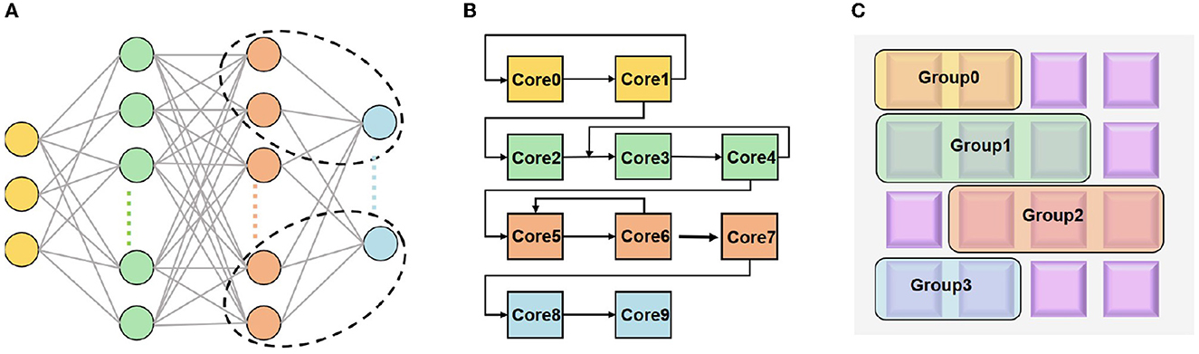
Figure 1. Illustration of mapping (A) a neural network onto neuromorphic hardware with two stages: (B) logical mapping; (C) physical mapping.
The logical cores can be represented by a graph G(V, E), thus the physical mapping can be viewed to place G(V, E) on a circuit graph T(U, S). V and U denote the sets of nodes, i.e., logical cores and physical cores, respectively; E and S denote the sets of edges, i.e., connections between logical cores and physical cores, respectively. Specifically, the physical mapping can be described as follows:
where vi and vj denote the i-th and j-th nodes (i.e., core) in V, respectively; |V| and |U| represent the numbers of logical and physical cores, respectively. Above constraints imply one-to-one mapping from logical cores to physical cores. Furthermore, we denote the weighted edges (#packets) between vi and vj as cij and denote the Manhattan distance between map(vi) and map(vj) as Mij, i.e., Mij = |xi − xj| + |yi − yj| where (xi, yi) and (xj, yj) are the coordinates of the two physical cores on the 2D physical plane. Let's define E|h| as the energy of transmitting a routing packet through a single hop distance, and define Lij as the communication latency with a routing packet between map(vi) and map(vj), respectively. With the above definitions, the total communication cost Ccost (Myung et al., 2021), the average communication latency L (Amin et al., 2020), and the average power consumption P (Pei et al., 2019; Ma et al., 2020) can be calculated by
where the Ni is the number of routing packets received by the physical core map(vi). The working period T can be approximately viewed as a fixed variable.
2.2. Logical mapping
At present, most researchers adopt 2D partition in logical mapping by splitting both input and output channel dimensions. The partition of the input channel dimension would compromise accuracy due to the accumulation of psums, while the partition of the output channel dimension would cause the requirement for data reshaping in the next layer. Besides the 2D partition, some works such as Simba (Shao et al., 2019; Zimmer et al., 2020) and Tianjic (Pei et al., 2019; Deng et al., 2020) can support 4D partition further on the feature map width and height. However, current mapping strategies face some challenges as shown in Figure 2, including the data overlap between the feature map partition, the psum accumulation in the input channel partition, and the data reshaping in the output channel partition.
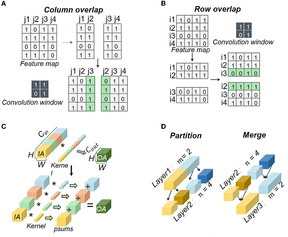
Figure 2. Typical challenges in neural network partition: (A) column-wise overlap; (B) row-wise overlap; (C) psum accumulation; (D) data reshaping. The symbol * means convolution.
The additional storage overheads in a core can be generated by the row-wise overlap Srow_add, the column-wise overlap Scol_add, the psum Sp_add, and the reshaped data Sre_add, which also result in additional computation latency. The additional storage and computation latency can be obtained by
where Sadd denotes the additional storage overhead in a core. fi(·) represents the function for processing the additional data. Note that we have fi(0) = 0. tadd_1 is the additional computation latency of a core neglecting the additional latency caused by the physical mapping. Because the partition depth of input channels is equal to that of each weight filter, all of these partition methods are viewed as the synchronous partition in this work.
2.3. Physical mapping
The optimal physical mapping is acknowledged to be an NP-hard problem (Myung et al., 2021). The 2D mesh topology is widely adopted by neuromorphic hardware owing to its high throughput and scalability (Painkras et al., 2013; Akopyan et al., 2015; Davies et al., 2018; Pei et al., 2019; Shao et al., 2019; Deng et al., 2020; Zimmer et al., 2020). And the deadlock occurs in the 2D mesh usually. When the requested number of packets is more than that of the packet buffer size, the cores wait each other infinitely, thus deadlock occurs. To avoid deadlock and optimize the communication latency and energy in physical mapping, reinforcement learning (Ma et al., 2019; Barrett et al., 2020; Feng et al., 2020; Cappart et al., 2021; Mazyavkina et al., 2021) is used by some researchers (Wu et al., 2020; Myung et al., 2021). Moreover, Figure 3 explains the communication latency in a multi-core architecture after physical mapping (Amin et al., 2020). Because the 8-th and the 9-th cores send data to the 11-th core concurrently, the 10th core is crossed twice by them due to the physical route. Thus, the latency is generated by the 10th core.
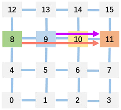
Figure 3. Example for helping understand communication latency caused by physical mapping.
There are many heuristic solutions to physical mapping, such as the genetic algorithm (GA) (Lei and Kumar, 2003; Zhou et al., 2006) and the simulated annealing (SA) (Ma et al., 2020) algorithm. Some teams (Davies et al., 2018; Shao et al., 2019; Zimmer et al., 2020) also use the greedy algorithm to optimize the communication latency and energy. We use tadd_2 to denote the additional computation latency of a core when considering the physical mapping. It can be obtained by
where gi(·) represents the function for processing above additional data under the condition of physical mapping. Similarly, we have gi(0) = 0.
3. Mapping limit
3.1. Logical mapping limit
For logical mapping, we introduce a theoretical description. We denote the sets of weights (W), input activations (IA), and output activations (OA) of the i-th and j-th core as Wi, Wj, IAi, IAj, OAi, and OAj, and further denote the storage volume of W and IA in each core as SW and SIA, respectively. Then, the logical mapping can be described as
where Smem represents the total memory volume of a core. The non-overlap of OA indicates each output activation is calculated only once. Because OA will be transmitted to the IA memory of the cores for the next layer, Smem does not take SOA into account.
The additional storage overhead for a core generated in partition can be calculated by:
where μ(·) represents the unit step function, s represents the stride of the filter, Hin, Win, Hout, and Wout represent the height and width sizes of IA and OA, respectively. kw and kh are the width and height sizes of each weight kernel. And bp and b represent the bit-width of psum and IA, respectively. The logical mapping limit means that the logical mapping does not produce any additional storage overhead, which can be described as
When we approach the logical mapping limit, the values of Srow_add, Scol_add, Sp_add, Sre_add, tadd_1, and tadd_2 should be zero.
3.2. Physical mapping limit
After the logical mapping stage, the logical cores would be mapped onto the physical cores in a real chip. With the aforementioned graph representation, we optimize the average communication latency (L) and power consumption (P) without deadlock. The physical mapping limit here implies all logical cores are physically placed very close, especially being neighbors with Manhattan distance equal to one, which can be described as
Then, the communication cost can be reduced to
Because W and IA must be put in cores, the minimum of Ccost is the sum of W and IA. Now, the communication cost can be given as follows:
The average communication latency and power consumption can be the communication latency and power consumption by transmitting a routing packet between two neighboring cores due to Mij = 1.
In short, integrating the logical mapping limit and the physical mapping limit, the overall mapping limit follows
To approach the mapping limit, a closed-loop mapping strategy is proposed in the next section.
4. Approaches
4.1. Closed-loop mapping strategy
To approach the logical mapping limit, we propose a closed-loop mapping strategy with two forms. As illustrated in Figure 4, one form is based on IA, and the other is based on W. Taking four cores and the IA-based form as an example (see Figure 4A), the computing process can be described as follows. In the first phase, each core performs the convolution operation between IAi and Wi. At the end of the first phase, each core keeps its Wi stationary and sends its IAi to the downstream core. In the next phase, each core performs the convolution operation between Wi and its newly received IA. This loop would be closed when all cores have performed a complete convolution operation between its local Wi and all IAs. In this example, the loop needs four phases to close, and then we can get all OAs distributed in the four cores. The computing process can be summarized as
where N denotes the number of cores used for the layer and t is the index of phases. It can be seen that the above mapping strategy does not consume any additional memory overhead, satisfying the logical mapping limit given in Equations (21)–(22). For the W-based closed-loop mapping, the overall flow is similar. The only difference is that each core keeps IA stationary and exchanges W between cores.
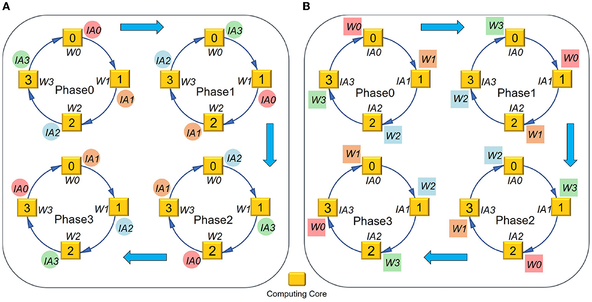
Figure 4. Closed-loop mapping based on (A) IA or (B) W.
In order to implement the closed-loop mapping on hardware, a 4D partition with synchronous and asynchronous methods is proposed for logical mapping, which is more flexible and general than the existing 2D synchronous partition. Here “4D” refers to Cin, Cout, and two dimensions of each feature map.
First, we try the 4D synchronous partition, as illustrated in Figure 5. Note that I, J, m, and n represent the number of partition groups in feature map height, feature map width, Cin, and Cout dimensions, respectively. kw and kh are the width and height sizes of each weight kernel. In the synchronous partition, W should be broadcasted along the feature map dimensions I×J times, and IA should be broadcasted along the output channel dimension n times. Therefore, the redundancy of storage caused by this partition is
Moreover, the number of allocating cores is
The resulting storage overheads for IA and W in each core should be
In short, the additional storage overhead on hardware given the 4D synchronous partition can be
Apparently, Equation (21) can only be satisfied under the condition IJn = 1, but Equation (22) cannot be satisfied under this case because psums exist. Therefore, the synchronous 4D partition fails to approach the logical mapping limit.
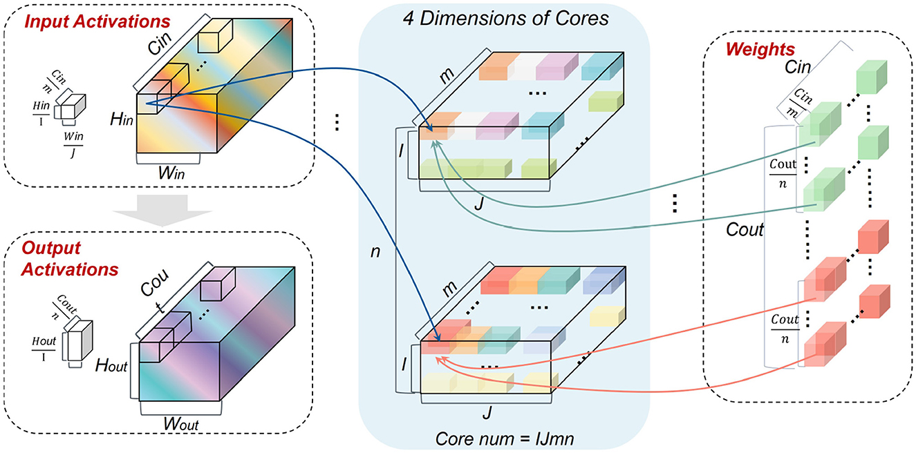
Figure 5. Illustration of the 4D synchronous mapping.
In order to approach the logical mapping limit described in Equations (21)–(22), we further propose an asynchronous partition method based on the closed-loop mapping strategy. Corresponding to the IA-based closed-loop mapping, the asynchronous partition method selects Cin of IA and Cout of W to partition. Taking N = 4 as an example, it can be seen from Figure 6A that both Cin of IA and Cout of W are partitioned into m = n = N groups. Then, the resulting IA and W in each core can satisfy Equation (21) without duplication. The reshaping overhead does not exist because the shape of OA is consistent with that of IA. Because psums can be accumulated locally, the psum communication also does not exist. Therefore, all additional storage overheads are zero and Equation (22) is satisfied. For the W-based closed-loop mapping in Figure 6B, the overall idea is similar to the IA-based case while Hin of IA and Cin of W are selected to partition. For the asynchronous closed-loop mapping, the storage overheads for IA and W in each core are
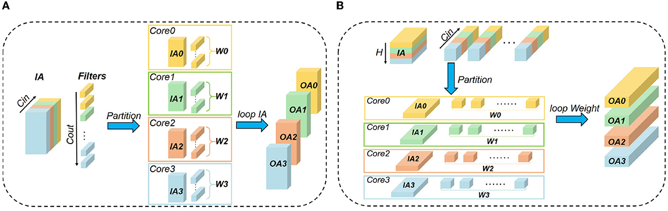
Figure 6. Illustration of the 4D asynchronous closed-loop mapping: (A) exchanging IA as Figure 4A; (B) exchanging W as Figure 4B.
With the above knowledge, we make an explanation for the words “synchronous” and “asynchronous.” In this work, “synchronous” means both the partitioning dimensions of IA and W involve Cin. In contrast, “asynchronous” means the partitioning dimensions of IA and W are different, for example in Figure 6A partitioning IA along the Cin dimension while partitioning W along the Cout dimension, and in Figure 6B partitioning IA along the Hin dimension while partitioning W along the Cin dimension. In the asynchronous closed-loop mapping, one of IA and W in each core has a complete Cin dimension, and the other is gradually acquired by exchanging data between cores without any redundant data copy.
4.2. Hamilton loop algorithm for physical mapping
To satisfy Equation (23) of the physical mapping limit, the Hamilton Loop Algorithm (HLA) is proposed for the closed-loop mapping strategy with asynchronous partition. Taking 12 cores as an example, it can be seen from Figure 7A that the Manhattan distance of every two logically neighboring cores equals 1, i.e., satisfying Mij = 1 as given in Equation (23). The physical mapping form can be flexibly arranged according to the array form of the available physical cores, e.g., 4 × 3, 3 × 4, and 6 × 2. Notice that the number of cores cannot be odd, as illustrated in Figure 7B. In those cases, Equation (23) cannot be satisfied unless there is a diagonal communication path. Usually, only one Hamiltonian loop is needed. A fast algorithm is proposed to find a Hamiltonian loop, whose pseudo-codes are given in Algorithm 1.
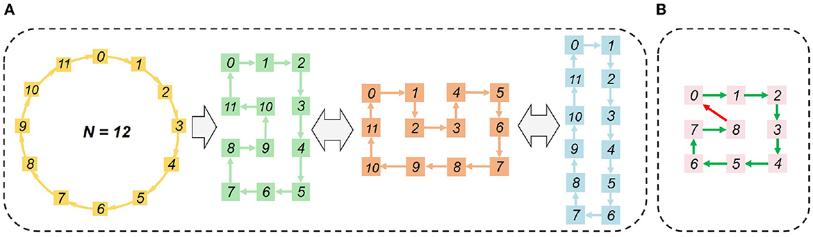
Figure 7. HLA-based physical mapping: (A) even number of cores; (B) odd number of cores.
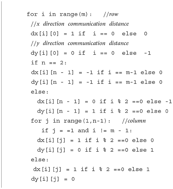
Algorithm 1. Fast algorithm to find a Hamiltonian loop.
5. Experimental results
The mapping methods are implemented on a 28nm neuromorphic chip, TianjicX (Ma et al., 2022), which adopts a decentralized manycore architecture with 160 functional cores. Each core has 128 multipliers and accumulators (MACs) for parallel execution operations in neural networks. To maintain accuracy as high as possible, the precision for accumulating psums is 32-bit. TianjicX supports the aforementioned 4D partition methods. The testing system includes a host computer, an Intel Arria 10 FPGA, four TianjicX chips, and an oscilloscope, as presented in Figure 8. The parameters and inputs of neural networks can be downloaded onto the chip by the configuration software on the host computer. The oscilloscope (RIGOL MSO8104) is used to measure the running time. Notice that the results of logical mapping are produced by the TianjicX simulator, while the results involving physical mapping are measured from the real chip.
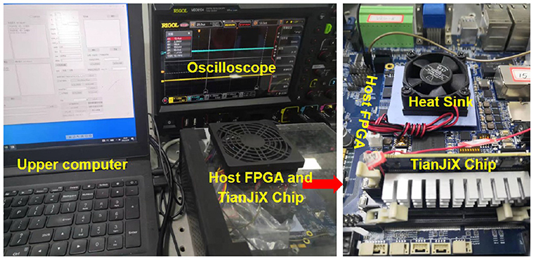
Figure 8. Testing system based on the TianjicX neuromorphic chip.
5.1. Analysis of logical mapping
We focus our application measurements on the ResNet50 (He et al., 2016), which is often used to benchmark by many hardwares (Jiao et al., 2020; Zimmer et al., 2020; Jouppi et al., 2021). However, as we do not have an automatic mapping tool at the current stage, we select a portion of the ResNet50 convolutional network for experimental analyses. In essence, the methodology can be extended to the whole convolutional networks in principle. To optimize the running time of each dimension, the synchronous partition method is selected as a baseline for investigation. The benchmarking layers are the 5-th and 6-th layers of ResNet50. The dimension settings of synchronous mapping are listed in Table 1. J, I, m and n represent the numbers of partition groups in the width, height, input channel, and output channel dimensions, respectively. First, from Model 1 to Model 6, I × J is set to a constant, 28, to explore the influence of partitioning I, J on the running clocks. Second, from Model 7 to Model 12, J × m = const and I × m = const are set to compare the influence priority of J, I, and m in dimension partition. Third, from Model 13 to Model 15, the influence priority is further compared among I, J, m, and n. Finally, we analyze the impact of changing partition dimensions on the running latency and computing efficiency.
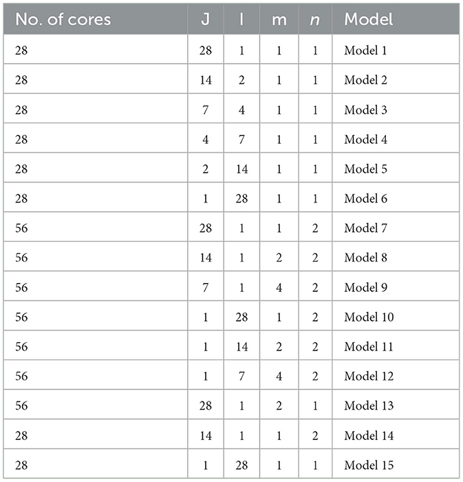
Table 1. Dimension settings of synchronous partition.
The experimental results of partitioning different dimensions are provided in Figure 9. From Figure 9A, it can be seen that the close the values between J and I, the shorter running time can be achieved. Meanwhile, we observe that the latency results of Model 1–6 present small variance, which implies that the partition of feature map dimensions has a negligible impact on the execution latency. From Figure 9B, it can be seen that the running time would be increased when we partition Cin, which introduces additional accumulation of psums and extra inter-core communication. As Figure 9C shows, although Model 7 introduces reshaping latency as n increases, it still reduces the total running clocks by 8000 owing to the decrease of m. It indicates that the partition of Cin has a larger impact on the running time than the partition of Cout. Similarly, by comparing Model 14 and Model 15, we find the partition of Cout has larger impact than the partition of feature map dimensions. Overall, the accumulation and communication of psums caused by partitioning Cin has the greatest impact on the execution latency, while reshaping caused by partitioning Cout has a greater impact than overlapping caused by partitioning feature map dimensions. With the above knowledge, it is possible to optimize execution latency by elaborating partition method.
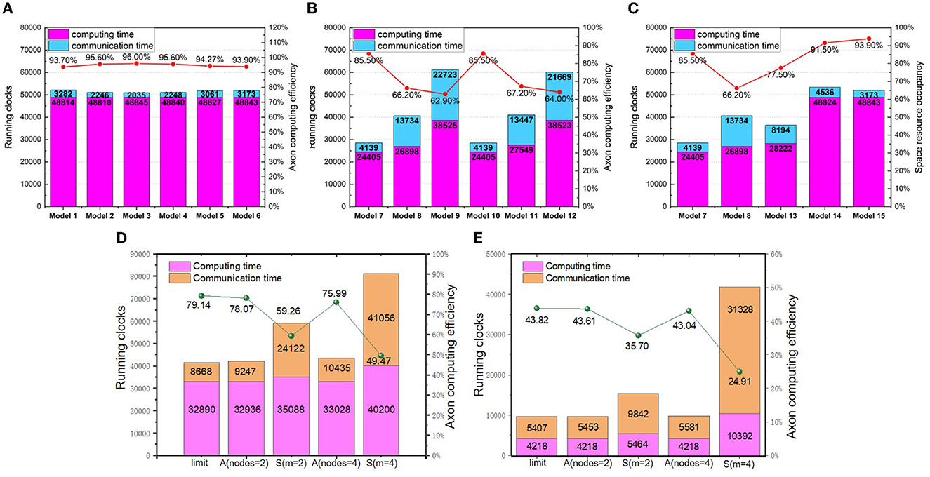
Figure 9. The logical mapping of running clocks and computing efficiency (A) synchronous partition of changing I and J; (B) synchronous partition of changing m, (I, J); (C) synchronous partition of changing m, n, and (I, J) (D) asynchronous partition with the 15-th layer of ResNet50; (E) asynchronous partition with the 16-th layer of ResNet50.
As aforementioned, the asynchronous partition based on the closed-loop mapping strategy can approach the mapping limit. To demonstrate its superior performance, we compare the running latency and computing efficiency of both synchronous partition and asynchronous partition. We use two types of layers: one is the 15-th layer of ResNet50 with 3 × 3 weight kernels, and the other is the 16-th layer of ResNet50 with 1 × 1 weight kernels. The model settings for the two benchmarking layers are respectively listed in Tables 2, 3.
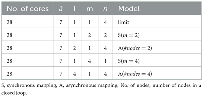
Table 2. Dimension setting of synchronous and asynchronous partition for the 15-th layer of ResNet50.
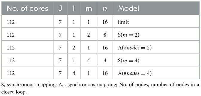
Table 3. Dimension setting of synchronous and asynchronous partition for the 16-th layer of ResNet50.
The experimental results are depicted in Figures 9D, E. Due to the limited number of primitive instructions in TianjicX, the maximum number of nodes in a closed loop cannot be larger than four. As Figure 9E presents, the running latency under asynchronous partition based on the closed-loop mapping is faster than that of synchronous mapping. For example, the running latency of the 16-th layer can be improved by 4.12 × under four nodes in a loop. Without the communication of psums, the communication latency of asynchronous mapping can also be greatly reduced.
5.2. Analysis of HLA physical mapping
To test the latency of HLA, we select all-to-all communication to conduct experiments. The 15-th layer of ResNet50 with 98KB parameters is the target workload. The all-to-all communication topology is illustrated in Figure 10A. The communicating latency is tested on TianjicX by enabling 4, 8, 16, or 32 cores. The energy consumption is estimated through simulation. Each case is tested with multiple physical mapping methods, including HLA, sequential neighboring placement with and without multicast (Myung et al., 2021), and several prior placement methods, including sequential placement (BS) (Wu et al., 2020), random search (RS) (Wu et al., 2020), simulated annealing (SA), and the RL-based approach (Wu et al., 2020). Due to the deadlock issue, we do not give the results of the zigzag physical mapping (Ma et al., 2020).
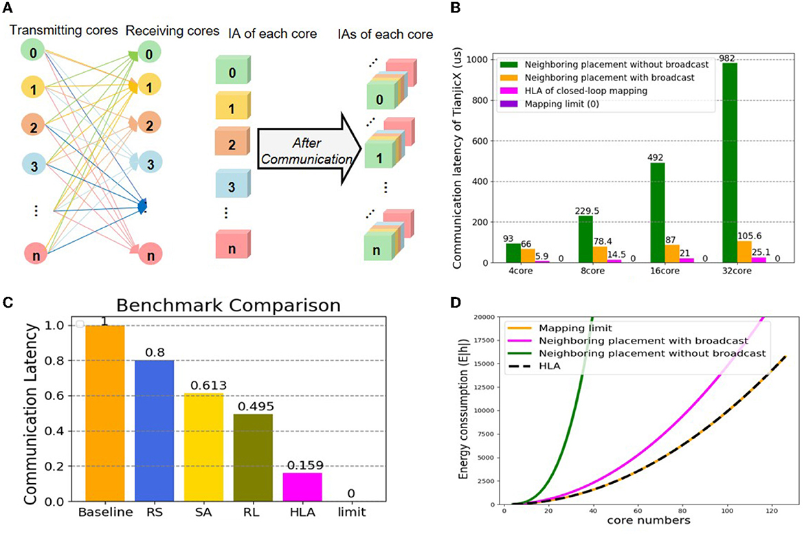
Figure 10. The physical mapping of latency and consumption (A) all-to-all communication between cores; (B) comparing communication latency between the neighboring placement, the mapping limit, and HLA; (C) comparing communication latency between prior methods, the mapping limit, and HLA; (D) comparing energy consumption between the neighboring placement, the mapping limit, and HLA.
The communication latency results can be found in Figures 10B, C. As predicted, the communication latency of HLA is the shortest among all tested physical mapping methods, which is quite close to the mapping limit. The communication latency of HLA can be reduced by 4.22 × compared to the neighboring placement with broadcast, and reduced by 84.1, 80.1, 74.1, and 67.9% compared to BS, RS, SA, and RL, respectively. Due to the launching delay of chip primitives, the communication latency increases as the number of used cores grows. The communicating latency of HLA approaches that of the mapping limit if there is no launching overhead. When using the HLA physical mapping, all cores are parallel to communicate without deadlock.
Assuming the number of cores is N and the data of a core for communication is V, the total energy consumption of the mapping limit, HLA and the neighboring placement with broadcast and without broadcast can be calculated as follows:
where EHLA, Elimit, EN_B, and EN_W_B represent the energy consumption of under HLA, the mapping limit, the neighboring placement with broadcast, and the neighboring placement without broadcast, respectively. The energy results can be found in Figure 10D. The energy consumption of all methods increases as the number of the allocated cores grows. Obviously, the energy consumption under the neighboring placement is much higher than that under the mapping limit, while the energy consumption under HLA is equal to that under the mapping limit.
In short, the HLA physical mapping based on the closed-loop mapping strategy shows significant superiority on reducing communication latency and energy consumption compared with other methods. More importantly, the HLA physical mapping can approach the mapping limit.
5.3. Integration of logical and physical mapping
To demonstrate the performance of asynchronous logical mapping and HLA physical mapping based on the closed-loop mapping strategy, we deploy neural layers on TianjicX. The experimental results are provided in Figure 11. Again, Figures 11A, B evidence the superior latency of our closed-loop mapping strategy compared to the conventional synchronous mapping with Cin partition adopted by Simba (Shao et al., 2019; Zimmer et al., 2020), Tianjic (Pei et al., 2019; Deng et al., 2020), and other neural network accelerators (Han et al., 2016; Jouppi et al., 2017; Parashar et al., 2017; Shin et al., 2017; Chen et al., 2019). The better computing efficiency of the closed-loop mapping strategy is also evidenced by Figures 11C, D. Specifically, with four nodes in a closed loop, the running time can be reduced by 7.6 × for the 15-th layer of ResNet 50, and the computing efficiency can be improved by 8.8 × for the 16-th layer. The proposed closed-loop mapping strategy implemented by integrating the asynchronous partition and the HLA placement can approach the mapping limit.
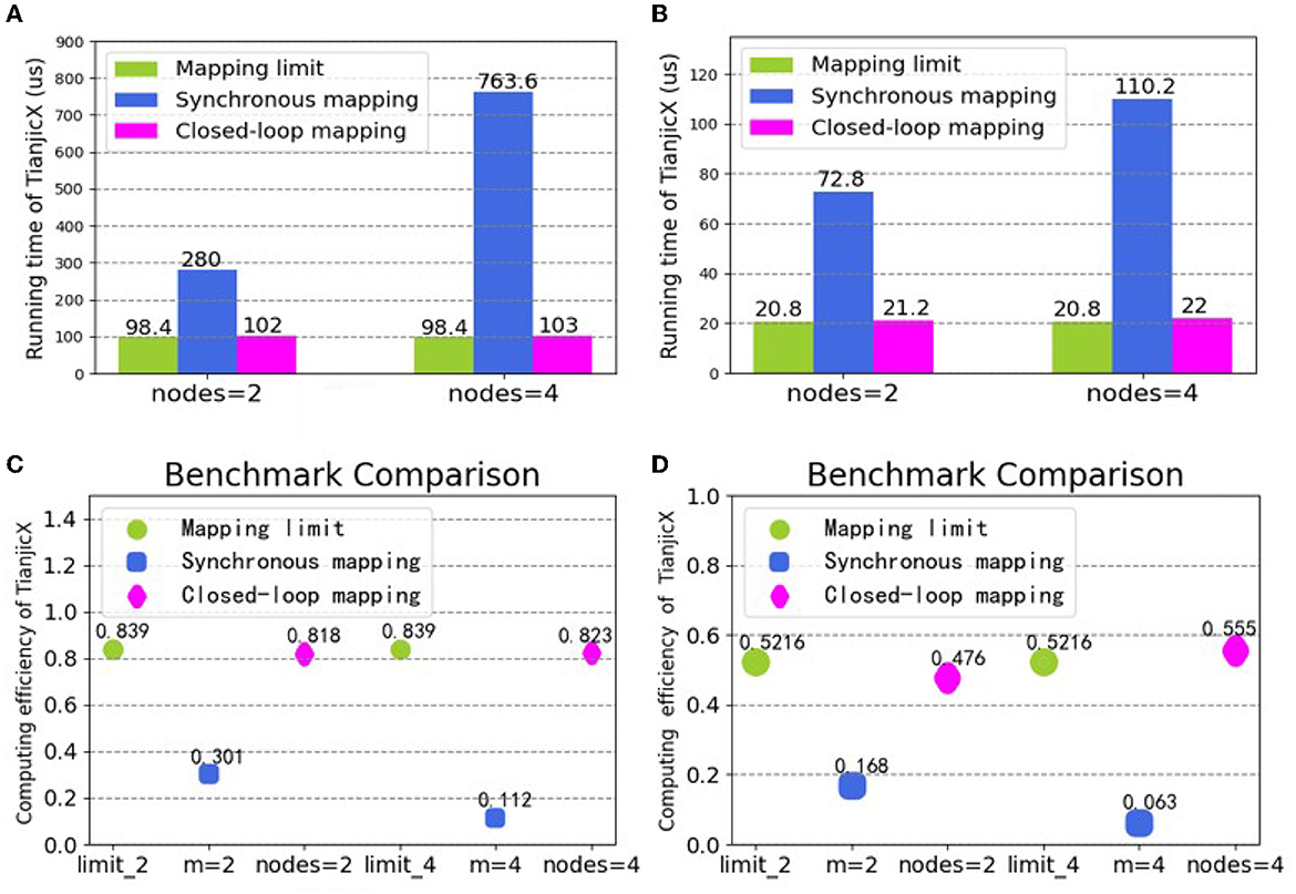
Figure 11. Running time and computing efficiency by integrating the logical and physical mapping under the closed-loop mapping strategy: (A) running time for the 15-th layer of ResNet50; (B) running time for the 16-th layer of ResNet50; (C) computing efficiency for the 15-th layer of ResNet50; (D) computing efficiency for the 16-th layer of ResNet50.
6. Conclusion and discussion
In this work, we propose the mapping limit concept for neuromorphic hardware based on the decentralized manycore architecture, which points out the resource saving upper limit during model deployment. To approach the mapping limit, we further propose the closed-loop mapping strategy that includes the asynchronous 4D partition for logical mapping and the HLA placement for physical mapping. Our experiments demonstrate the superiority of the proposed mapping methods. For example, compared to conventional synchronous Cin partition, our mapping methods improve the running time and computing efficiency by 7.6× and 8.8×, respectively, which can approach the mapping limit.
Generally, the mapping schemes for multi-core system can be divided into two processes: the first is the logical mapping process and the second is the physical mapping process. Furthermore, the logical mapping can be divided into two sets of models, which are synchronization and asynchronization. Most of the previous researches adopt the synchronization model based on the 2D mapping system (Shao et al., 2019; Ma et al., 2020; Wu et al., 2020; Myung et al., 2021), which only partitions the in-channel and out-channel of the neural network. And these researches focus on the physical mapping based on the 2D mapping system, while the 4D mapping system is a general model that has wider applications. Based on our 4D mapping system, we propose the mapping limit concept for the multi-core system. In the 4D mapping system, both the synchronization model and asynchronization model are demonstrated through intensive experiments. To achieve the mapping limit, we adopt the asynchronization mode to integrate the logical process and the physical process by the closed-loop mapping strategy.
Since the GPU is not a distributed architecture, the optimized result may be slightly rather than significantly improved in terms of energy consumption and computational speed. With the emergence of the decentralized architecture, the multi-core system is expected to be widely adopted due to its high-parallelism and memory locality (Painkras et al., 2013; Akopyan et al., 2015; Han et al., 2016; Parashar et al., 2017; Shin et al., 2017; Davies et al., 2018; Chen et al., 2019; Pei et al., 2019; Shao et al., 2019; Deng et al., 2020; Zimmer et al., 2020). Therefore, we are convinced that our proposed methods will provide a systematic solution to map neural networks onto multi-core systems, and provide guidance for further development of auto-mapping tools. Moreover, with the proposed mapping limit and the closed-loop mapping strategy, it is possible to build a general and efficient mapping framework for multi-core system in the future.
Data availability statement
The raw data supporting the conclusions of this article will be made available by the authors, without undue reservation.
Author contributions
SW proposed the idea, designed and did the experiments, and wrote the manuscript. SW and QY conducted the algorithm modeling work, contributed to the analysis, and interpretation of results. SW, QY, and TX conducted the design and implementation of the hardware testing platform. CM led the discussion and revised it. JP directed the project and provided overall guidance. All authors contributed to the article and approved the submitted version.
Funding
This work was partially supported by Science and Technology Innovation 2030—New Generation of Artificial Intelligence, China Project (No. 2020AAA0109100).
Conflict of interest
The authors declare that the research was conducted in the absence of any commercial or financial relationships that could be construed as a potential conflict of interest.
Publisher's note
All claims expressed in this article are solely those of the authors and do not necessarily represent those of their affiliated organizations, or those of the publisher, the editors and the reviewers. Any product that may be evaluated in this article, or claim that may be made by its manufacturer, is not guaranteed or endorsed by the publisher.
References
Akopyan, F., Sawada, J., Cassidy, A., Alvarez-Icaza, R., Arthur, J., Merolla, P., et al. (2015). Truenorth: design and tool flow of a 65 mw 1 million neuron programmable neurosynaptic chip. IEEE Trans. Comput. Aided Des. Integr. Circuits Syst. 34, 1537–1557. doi: 10.1109/TCAD.2015.2474396
Amin, W., Hussain, F., Anjum, S., Khan, S., Baloch, N. K., Nain, Z., et al. (2020). Performance evaluation of application mapping approaches for network-on-chip designs. IEEE Access 8, 63607–63631. doi: 10.1109/ACCESS.2020.2982675
Barrett, T., Clements, W., Foerster, J., and Lvovsky, A. (2020). “Exploratory combinatorial optimization with reinforcement learning,” in Proceedings of the AAAI Conference on Artificial Intelligence, Vol. 34 (New York, NY), 3243–3250. doi: 10.1609/aaai.v34i04.5723
Cappart, Q., Moisan, T., Rousseau, L.-M., Prémont-Schwarz, I., and Cire, A. A. (2021). “Combining reinforcement learning and constraint programming for combinatorial optimization,” in Proceedings of the AAAI Conference on Artificial Intelligence, Vol. 35 (Palo Alto, CA), 3677–3687. doi: 10.1609/aaai.v35i5.16484
Chen, Y.-H., Yang, T.-J., Emer, J., and Sze, V. (2019). Eyeriss v2: a flexible accelerator for emerging deep neural networks on mobile devices. IEEE J. Emerg. Select. Top. Circuits Syst. 9, 292–308. doi: 10.1109/JETCAS.2019.2910232
Davies, M., Srinivasa, N., Lin, T.-H., Chinya, G., Cao, Y., Choday, S. H., et al. (2018). Loihi: a neuromorphic manycore processor with on-chip learning. IEEE Micro 38, 82–99. doi: 10.1109/MM.2018.112130359
Deng, L., Liang, L., Wang, G., Chang, L., Hu, X., Ma, X., et al. (2018). Semimap: a semi-folded convolution mapping for speed-overhead balance on crossbars. IEEE Trans. Comput. Aided Design Integr. Circuits Syst. 39, 117–130. doi: 10.1109/TCAD.2018.2883959
Deng, L., Wang, G., Li, G., Li, S., Liang, L., Zhu, M., et al. (2020). Tianjic: A unified and scalable chip bridging spike-based and continuous neural computation. IEEE J. Solid-State Circuits 55, 2228–2246. doi: 10.1109/JSSC.2020.2970709
Feng, K., Wang, Q., Li, X., and Wen, C.-K. (2020). Deep reinforcement learning based intelligent reflecting surface optimization for miso communication systems. IEEE Wireless Commun. Lett. 9, 745–749. doi: 10.1109/LWC.2020.2969167
Gholami, A., Yao, Z., Kim, S., and Mahoney, M. W. (2021). AI and Memory Wall[j]. RiseLab Medium Post.
Han, S., Liu, X., Mao, H., Pu, J., Pedram, A., Horowitz, M. A., et al. (2016). EIE: efficient inference engine on compressed deep neural network. ACM SIGARCH Comput. Architect. News 44, 243–254. doi: 10.1145/3007787.3001163
He, K., Zhang, X., Ren, S., and Sun, J. (2016). “Deep residual learning for image recognition,” in Proceedings of the IEEE Conference on Computer Vision[0mm][8mm] and Pattern Recognition (Las Vegas), 770–778. doi: 10.1109/CVPR.2016.90
Jiao, Y., Han, L., Jin, R., Su, Y.-J., Ho, C., Yin, L., et al. (2020). “7.2 a 12nm programmable convolution-efficient neural-processing-unit chip achieving 825tops,” in 2020 IEEE International Solid-State Circuits Conference-(ISSCC) (San Francisco, CA), 136–140. doi: 10.1109/ISSCC19947.2020.9062984
Jouppi, N. P., Yoon, D. H., Ashcraft, M., Gottscho, M., Jablin, T. B., Kurian, G., et al. (2021). “Ten lessons from three generations shaped Google's tpuv4i: industrial product,” in 2021 ACM/IEEE 48th Annual International Symposium on Computer Architecture (ISCA) (Valencia), 1–14. doi: 10.1109/ISCA52012.2021.00010
Jouppi, N. P., Young, C., Patil, N., Patterson, D., Agrawal, G., Bajwa, R., et al. (2017). “In-datacenter performance analysis of a tensor processing unit,” in Proceedings of the 44th Annual International Symposium on Computer Architecture (Toronto, ON), 1–12. doi: 10.1145/3140659.3080246
Lei, T., and Kumar, S. (2003). “A two-step genetic algorithm for mapping task graphs to a network on chip architecture,” in Euromicro Symposium on Digital System Design, 2003 (Belek-Antalya), 180–187.
Ma, C., Zhao, Q., Li, G., Deng, L., and Wang, G. (2020). A deadlock-free physical mapping method on the many-core neural network chip. Neurocomputing 401, 327–337. doi: 10.1016/j.neucom.2020.03.078
Ma, Q., Ge, S., He, D., Thaker, D., and Drori, I. (2019). Combinatorial optimization by graph pointer networks and hierarchical reinforcement learning. arXiv preprint arXiv:1911.04936.
Ma, S., Pei, J., Zhang, W., Wang, G., Feng, D., Yu, F., et al. (2022). Neuromorphic computing chip with spatiotemporal elasticity for multi-intelligent-tasking robots. Sci. Robot. 7:eabk2948. doi: 10.1126/scirobotics.abk2948
Mazyavkina, N., Sviridov, S., Ivanov, S., and Burnaev, E. (2021). Reinforcement learning for combinatorial optimization: a survey. Comput. Oper. Res. 134:105400. doi: 10.1016/j.cor.2021.105400
Myung, W., Lee, D., Song, C., Wang, G., and Ma, C. (2021). Policy gradient-based core placement optimization for multichip many-core systems. IEEE Trans. Neural Netw. Learn. Syst. 1–15. doi: 10.1109/TNNLS.2021.3117878
Painkras, E., Plana, L. A., Garside, J., Temple, S., Galluppi, F., Patterson, C., et al. (2013). Spinnaker: a 1-w 18-core system-on-chip for massively-parallel neural network simulation. IEEE J. Solid State Circuits 48, 1943–1953. doi: 10.1109/JSSC.2013.2259038
Parashar, A., Rhu, M., Mukkara, A., Puglielli, A., Venkatesan, R., Khailany, B., et al. (2017). SCNN: an accelerator for compressed-sparse convolutional neural networks. ACM SIGARCH Comput. Architect. News 45, 27–40. doi: 10.1145/3140659.3080254
Pei, J., Deng, L., Song, S., Zhao, M., Zhang, Y., Wu, S., et al. (2019). Towards artificial general intelligence with hybrid tianjic chip architecture. Nature 572, 106–111. doi: 10.1038/s41586-019-1424-8
Shao, Y. S., Clemons, J., Venkatesan, R., Zimmer, B., Fojtik, M., Jiang, N., et al. (2019). “SIMBA: scaling deep-learning inference with multi-chip-module-based architecture,” in Proceedings of the 52nd Annual IEEE/ACM International Symposium on Microarchitecture (New Jersey, NJ), 14–27. doi: 10.1145/3352460.3358302
Shin, D., Lee, J., Lee, J., and Yoo, H.-J. (2017). “DNPU: an 8.1 tops/w reconfigurable CNN-RNN processor for general-purpose deep neural networks,” in 2017 IEEE International Solid-State Circuits Conference (ISSCC) (San Francisco, CA), 240–241. doi: 10.1109/ISSCC.2017.7870350
Vaswani, A., Shazeer, N., Parmar, N., Uszkoreit, J., Jones, L., Gomez, A. N., et al. (2017). “Attention is all you need,” in Advances in Neural Information Processing Systems, 30 (Long Beach, CA).
Von Neumann, J. (1993). First draft of a report on the EDVAC. IEEE Ann. Hist. Comput. 15, 27–75. doi: 10.1109/85.238389
Wu, N., Deng, L., Li, G., and Xie, Y. (2020). Core placement optimization for multi-chip many-core neural network systems with reinforcement learning. ACM Trans. Design Autom. Electron. Syst. 26, 1–27. doi: 10.1145/3418498
Zhou, W., Zhang, Y., and Mao, Z. (2006). “An application specific NOC mapping for optimized delay,” in International Conference on Design and Test of Integrated Systems in Nanoscale Technology, 2006 (Tunis), 184–188.
Keywords: neuromorphic chip, logical mapping, physical mapping, mapping limit, closed-loop mapping
Citation: Wang S, Yu Q, Xie T, Ma C and Pei J (2023) Approaching the mapping limit with closed-loop mapping strategy for deploying neural networks on neuromorphic hardware. Front. Neurosci. 17:1168864. doi: 10.3389/fnins.2023.1168864
Received: 18 February 2023; Accepted: 26 April 2023;
Published: 18 May 2023.
Edited by:
Huajin Tang, Zhejiang University, ChinaReviewed by:
Liliana Ibeth Barbosa Santillan, University of Guadalajara, MexicoJoseph Friedman, The University of Texas at Dallas, United States
Copyright © 2023 Wang, Yu, Xie, Ma and Pei. This is an open-access article distributed under the terms of the Creative Commons Attribution License (CC BY). The use, distribution or reproduction in other forums is permitted, provided the original author(s) and the copyright owner(s) are credited and that the original publication in this journal is cited, in accordance with accepted academic practice. No use, distribution or reproduction is permitted which does not comply with these terms.
*Correspondence: Jing Pei, cGVpakBtYWlsLnRzaW5naHVhLmVkdS5jbg==