 Jingfan Zhang1†Zhaoxiang Li2†‡
 Shuai Wang1*Yuan Dai1
 Ruirui Zhang1Jie Lai1Dongsheng Zhang1Ke Chen1Jie Hu2Weinan Gao3
 Jianshi Tang4Yu Zheng1
- 1Tencent Robotics X, Tencent Holdings, Shenzhen, Guangdong, China
- 2School of Computer Science, Yangtze University, Jingzhou, Hubei, China
- 3State Key Laboratory of Synthetical Automation for Process Industries, Northeastern University, Shenyang, China
- 4School of Integrated Circuits, Tsinghua University, Beijing, China
The dynamics of a robot may vary during operation due to both internal and external factors, such as non-ideal motor characteristics and unmodeled loads, which would lead to control performance deterioration and even instability. In this paper, the adaptive optimal output regulation (AOOR)-based controller is designed for the wheel-legged robot Ollie to deal with the possible model uncertainties and disturbances in a data-driven approach. We test the AOOR-based controller by forcing the robot to stand still, which is a conventional index to judge the balance controller for two-wheel robots. By online training with small data, the resultant AOOR achieves the optimality of the control performance and stabilizes the robot within a small displacement in rich experiments with different working conditions. Finally, the robot further balances a rolling cylindrical bottle on its top with the balance control using the AOOR, but it fails with the initial controller. Experimental results demonstrate that the AOOR-based controller shows the effectiveness and high robustness with model uncertainties and external disturbances.
1. Introduction
The control performance deterioration on real robots is often blamed on the inaccurate model. First, it is hard to model the robot accurately and to obtain the precise model parameters. In addition, the robotic system may vary during operation, so the inherent model also varies. Furthermore, some environmental changes in terrains, loads, etc. are also reflected as variations in the robot dynamics. The model issue is troublesome in general and could be hazardous for highly dynamic and statically unstable robots, such as two-wheel and wheel-legged robots. For example, the model-based optimal control is designed for the ballbot (Lauwers et al., 2006), but the model should be updated when a load, such as an arm, is equipped (Nagarajan et al., 2012). In addition, for the wheel-legged robot Ascento (Klemm et al., 2020), the optimality of the model-based control may be hard to be ensured when the working condition changes. Furthermore, for the two-wheel robot Segway, the robustness of the balance control may not overcome working condition variations, which lead to serious injuries (Ashurst and Wagner, 2015).
The issue on the model accuracy motivates the application of non-model-based or data-driven control algorithms, such as data-driven MPC (Willems et al., 2005; Jianwang and Ramirez-Mendoza, 2022) and adaptive dynamic programming (ADP) (Jiang and Jiang, 2012a, 2013, 2017; Bian and Jiang, 2016). For both of them, an optimal stabilizing controller can be trained using small data without system identification, which makes online implementation possible.
Particularly, the ADP consists of the policy iteration (PI) method and the value iteration (VI) method. The ADP was explored in our previous researches and proved to be useful, especially for the balance control of configuration changeable and statically unstable robots (Cui et al., 2021; Zhang et al., 2022). By the PI, the initial control should be stabilizing but not necessarily be optimal, and the training results in an approximated optimal controller (Jiang and Jiang, 2012a,b). This property is suitable when the configuration of the robot changes. By the VI, the initial control can be arbitrary and even manual or unstable. The training by the VI results in an initial optimal controller at the cost of longer iterations to converge (Bian and Jiang, 2016, 2022). This property is significant for statically unstable robots, because the training can start without any controller design. In the most recent study (Qasem et al., 2021), the proposed hybrid iteration combines the advantages of PI and VI. Moreover, the controller iteration in the ADP is robust to the noisy data in sense of data with the bounded noise leading to a controller bounded in a neighborhood of the nominal optimal solution (Pang et al., 2022). Compared with reinforcement learning applications on the balance control of two-wheel robots (majorly in simulation) (Raudys and Šubonienė, 2020; Guo et al., 2021), the ADP requires small data and the stability can be proved theoretically, which enables the training on real robots directly and removes the troublesome sim-to-real gap.
Besides the model uncertainty, another issue may affect the control performance is unmodeled disturbances on real robots. The disturbance may be caused by any mismatch between the ideal simulation and the real robot, such as the terrain changes, uncertain frictions and slight offsets of robot states, which are hard to be sourced and analyzed completely. For wheel-legged robots, a common consequence of these disturbances is the steady-state error. In our previous works, although the controller is stabilizing, the robot cannot stand still without extra manual adjustment, which is mentioned as an unsolved problem in Zhang et al. (2022). This phenomenon is common in real-robot experiments of two-wheel and wheel-legged robots (Jung and Kim, 2008; Huang et al., 2012; Zafar et al., 2019; Zhang et al., 2019; Zhou et al., 2021), but it is unnoticed if the asymptotic stability is not required strictly.
In the existing literature on wheel-legged robots, the steady-state error is eliminated by the centroidal adjustment in Zhou et al. (2019) and by arm acceleration control in Raza et al. (2021). In addition to the case-by-case solutions to the disturbance, a more systematic approach is to apply output regulation on selected outputs (Isidori and Byrnes, 1990; Huang, 2004). In Wang et al. (2021), the output regulation is applied to force the robot to stand still using the cart-pole model where the disturbance is estimated by an observer.
To overcome the both aforementioned issues by model uncertainties and unmodeled disturbances, a novel solution is the adaptive optimal output regulation (AOOR) (Gao and Jiang, 2016, 2022). Similar to the standard ADP, the training can be conducted on real robots directly, and the system identification is not needed. In the author's previous researches, the optimal output regulation has been applied to semi-autonomous vehicles (Huang et al., 2019) and connected autonomous vehicles (Gao et al., 2016, 2019; Gao and Jiang, 2017). However, there is no application on balance augmentation for wheel-legged robots.
In this paper, we design the AOOR-based controller on the wheel-legged robot Ollie (Figure 1) to achieve non-model-based optimal control and regulate it to stand still in various working conditions. Compared with our previous works (Cui et al., 2021; Wang et al., 2021; Zhang et al., 2022), the contributions in this paper are concluded as follows.
• In Cui et al. (2021) and Zhang et al. (2022), the robot is balanced but cannot stand still, which was stated as a limitation of the ADP algorithm. In this paper, the problem is solved by further regulating the velocity of the robot to zero in a systematic approach.
• The robot was forced to stand still when it is at the minimum height (Wang et al., 2021) based on the cart-pole model, but this model-based method cannot keep the robot standing still when robot configuration or the environment changes. In this paper, the data-driven approach based on the ADP is applied to regulate the robot adaptively.
• In addition to solving the problems in the scenarios of our previous works, more challenging scenarios are invoked to test the generality of the proposed control algorithm.
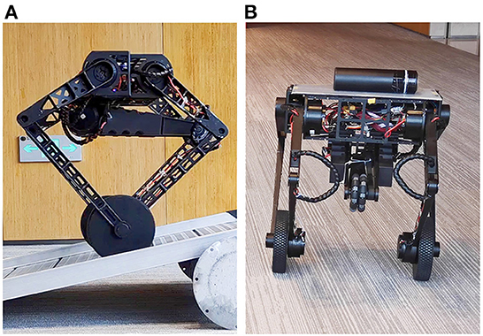
Figure 1. The wheel-legged robot Ollie. Many more maneuvers in action and experimental data are shown in the accompanying video. (A) Train the controller on a slope. (B) Test the controller to balance a cup.
The structure of the remaining paper is as follows. In Section 2.1, the robot system and the control framework are introduced briefly, with the problem statement of the control given in Section 2.3. In Section 3, the main controller design based on the AOOR is provided with its algorithm. In Section 4, the experiment results on the training process and the related testing process using the AOOR-based controller are demonstrated, and an interesting application is also shown. Finally, conclusions and several feasible future studies are given in Section 5.
2. Robotic system and control framework
2.1. Introduction to the robotic system
The robot we used in this paper is the wheel-legged robot Ollie. This robot was self-developed by Tencent Robotics X and was first released in both the plenary talk and the research paper (Wang et al., 2021) at ICRA 2021. Ollie (mechanical model shown in Figure 2) is designed using eight driving motors: four motors on the hips, two motors on the tail and two motors on the wheels. The five-bar linkage mechanism is used so that each leg is actuated by two motors on the base, without actuators on the knees. Based on the mechanical design, each five-bar leg is able to move along the x and z-axis in the leg plane, which keeps perpendicular to the robot base. Except for two-wheel balancing, the robot has the ability to switch flexibly between two-wheel and three-wheel modes. Moreover, the attitude of the base can be adjusted by changing the height of each leg, i.e., distance between the center of the wheel and the base in the leg plane. With an optimal mechanical design of legs, the robot can stride over obstacles, jump, and flip, demonstrating its strong ability to realize dynamic movements (Ackerman, 2021). The total weight of Ollie is around 15 kg. The height of the robot is between 0.33 and 0.7 m.
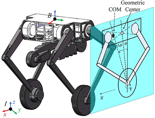
Figure 2. Mechanical design of the robot Ollie and simplified model on the sagittal plane, where the geometric center and the CoM are marked in a hollow circle and a filled circle, respectively. The actual pitch angle is the subtraction of the measured value θ and an offset Δθ, i.e., . The displacement of the robot in the x direction is denoted as x with its velocity ẋ. The wheel is actuated by the motor torque τ.
2.2. Robotic control framework
In order to keep Ollie moving with agile and flexible body poses at the same time of wheel balancing, the whole-body control (WBC) is used. The robotic control framework is shown in Figure 3. See details of the whole-body dynamics model and optimization formulation in the authors' previous publication (Zhang et al., 2022).
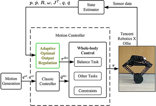
Figure 3. Control framework of the robot system.
Before the WBC module, an individual controller is designed to generate the reference torques τdes for the balancing task due to the nonminimum-phase property of the wheel-legged robot. Conventionally, references of the balancing task in the WBC are usually generated by controller design based on a simplified model (Klemm et al., 2020; Murtaza et al., 2020) or by a manual tuning controller (Zambella et al., 2019). To overcome the aforementioned model uncertainties and inaccuracy of model parameters and external disturbances (formally stated in Section 2.3), the AOOR is used to calculate balancing task references.
Other task references, such as attitudes and height of the robot, are obtained from the motion generation and classic controllers.
2.3. Problem statement
The problem mentioned in Zhang et al. (2022) is that it is hard for such a wheel-legged robot to keep standing completely still in different working conditions. In order to make the robot stand still, the center of mass (CoM) and the middle of wheels should be vertical. Therefore, the accurate estimation of the CoM position is crucial for model-based controllers, but the deviation from the expected position is inevitable in practice due to the nonuniform mass distribution and the assembly errors. This is presented in the sagittal plane in Figure 2, where the CoM of the floating base is assumed to be consistent with the geometric center but they are different in practice.
In the balancing task, the pitch angle , pitch angular velocity and the robot's linear velocity are regulated to zero by controlling the motor torque τ at the wheel. The balancing system can be expressed in the linear form
where , A ∈ ℝn×n and B ∈ ℝn×m (n = 3, m = 1). It must be highlighted that, due to the uncertain factors of the robotic system, it is hard to model an accurate expression of A and B, and they are not used in this paper.
Particularly, considering the deviation of the CoM, the real pitch angle is the subtraction of the measured value θ and an offset Δθ, i.e., (Note that subtraction is used to keep consistent with the formulation in Section 3), while the real value and the measured value are equal for the other two states (, ). Then, the dynamic model (Equation 1) is equivalent to
where , D ∈ ℝn×q (q = 1) and D = A[−Δ, θ, 0, 0]T.
In addition, to stop the robot at a fixed position, ẋ is chosen as the output to be regulated to zero, and the error is
where C = [0 0 1].
In this paper, we consider the balancing task in the WBC framework with the system described in Equations (2) and (3) with the unknown parameters A, B, and Δθ. The objective is to stabilize the system by optimal control adaptively and to regulate the output to zero.
3. AOOR-based balance control algorithm
One possible way to keep the wheel-legged robot standstill while balancing is to design a controller based on the AOOR. A similar data-driven optimal output regulation for linear systems with exogenous disturbances is proposed in Gao and Jiang (2016), but the controller design based on the similar data-driven method on the balance augmentation of wheel-legged robots is not trivial. In this section, we design the AOOR-based controller for the particular application on the balancing task of wheel-legged robots.
3.1. Model-based optimal output regulation
The standard state feedback control of the system (Equation 1) is
when (A, B) is stabilizable, where K ∈ ℝn×1 is a stabilizing feedback gain. The control law can be rewritten in the equivalent form for the system (Equation 2) as
where L = KZ + T with Z = [Δθ 0 0]T. In the control law (Equation 5), the first term regulates the state ζ, and the second term compensates the uncertainty D. Then, the original system (Equation 1) is asymptotically stable () if the unknown Z and T are solvable by the regulator equation (see the proof in Huang, 2004):
Due to the specific underactuated dynamics of the wheel-legged robot, there exists a unique solution of the regulation equation. It is self-evident because the steady-state must be ζ = [Δθ, 0, 0] for the standstill condition, and the torque is then fixed. However, for other types of robots, there may exist multiple solutions, and an optimization problem can be designed to solve the optimal solution (Gao and Jiang, 2016).
In this paper, the optimality is represented by solving the following constrained optimization problem for the state feedback control.
where Q ∈ ℝn×n is positive-definite and R ∈ ℝ is positive. The optimal solution is represented by the optimal feedback gain
where the positive-definite P* is the solution of the algebraic Riccati equation (ARE) (Lewis et al., 1995).
3.2. Data-driven optimal output regulation
In the data-driven approach, the main objective is to remove the dependency on the model parameter A, B and D, and determine the optimal solution (K*, P*) and (Z, T).
To determine the optimal feedback gain K*, by utilizing the collected data ζ(t) and τ(t), the optimization problem (Equation 7) is solved iteratively. Particularly, the dependency on A is removed by the Lyapunov equation
where j is the index of iteration. Meanwhile, the dependency on B is removed by the gain iteration
In addition, D is set as a variable to be determined in each iteration. When K and P converge, the results can be proved as the optimal solutions K* and P* (Kleinman, 1968).
To determine the regulation parameters (Z, T), a basis of Z is defined as such that with a scalar α and the second equation in the regulator (Equation 6) is satisfied. Notice that the construction of the basis of Z is slightly different from Gao and Jiang (2016) in this particular application on Ollie. Then, by defining a Sylvester map S:ℝn↦ℝn by S(Z) = −AZ, the first equation in the regulation equation is rewritten as
where B is represented by Equation (10) using K* and P* from the previous step, and D is solved in the previous step.
Then, if is available, the pair (Z, T) can be computed by solving the following linear equation
Finally, by setting L = K*Z + T, the optimal output regulation law in Equation (5) is attained.
The proposed AOOR is provided in Algorithm 1, with the related matrices defined in Equations (13) and (14), where the notation vec() denotes the vectorization, and ⊗ denotes the Kronecker product. It is suggested to check the conditioning number of Ψ and to avoid potential numerical problems caused by ill-conditioned matrix. The general idea of the proof follows from Gao and Jiang (2016), but the AOOR-based control is applied for the specific problem on the balance augmentation of wheel-legged robots. Due to the page limit, the detailed proof is omitted.
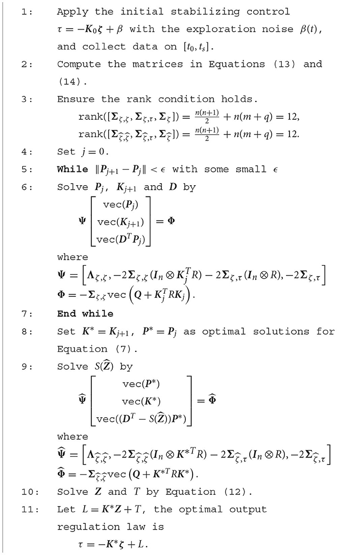
Algorithm 1. Adaptive optimal output regulation.
4. Experimental results
4.1. Experimental setup
In the experiment, the control framework in Figure 3 is realized by the CPU PICO-WHU4 at a frequency of 1 k Hz. The rotation of the floating base is measured by the onboard IMU at a frequency of 400 Hz. The experimental data are saved at a frequency of 1 k Hz. The rotation of each actuated joint is measured by the motor encoder. The reference velocity and the reference height of the robot are set by the operator using a remote controller.
4.2. Training
We train the data-driven optimal output regulation controller for Ollie in four scenarios to deal with uncertainties in model and disturbances. In our previous work (Cui et al., 2021; Zhang et al., 2022), the robot kept balanced, but it could not stand still, which was mentioned as a limitation. Hence, in the first two scenarios, we deal with the asymptotic stability problem in our previous works where the robot is at the height 0.33 m (Figure 4A) and the height 0.5 m (Figure 4B). Furthermore, we invoke two more challenging scenarios. In the third scenario, we mount an eccentric load of 3.5 kg in the front of the floating base (Figure 4C). As the floating base is about 11 kg, the heavy load would change the equilibrium point significantly. In the fourth scenario, we train the robot on a slope (Figure 4D). It is clear that extra torque is required to compensate for the component of gravity in the direction of the slope, which in turn implies that the equilibrium point changes. Notice that no information of the load (e.g., mass, shape, location) and the slope (e.g., gradient) is used in the training process, and they are treated as unknown disturbances.
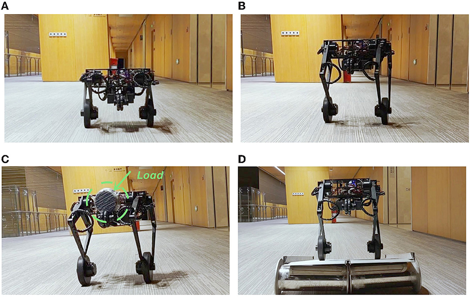
Figure 4. Images during the training. Many more maneuvers in action and experimental data are shown in the accompanying video. (A) Height = 0.33 m, (B) height = 0.5 m, (C) height = 0.5 m with the load, and (D) height = 0.5 m on the slope.
During the training, the initial controller gain K0 = [−74 − 26 − 10] is used, which is close to the resultant controller obtained from the VI training in Zhang et al. (2022). As the controller is stabilizing, the robot can move forward and backward repeatedly according to the remote control and the exploration noise β(t) = 1.6sin(8πt) + 0.8cos(12πt) is used to trigger more informative data. Training data of 6 s are collected for each experiment with the sampling interval 0.015 s. It means that, in Algorithm 1, t0 = 0, ts = 6 s, and tk+1 − tk = 0.015 s. Considering the sampling rate of 1 k Hz, there are 400 elements in each matrix in Equations (13) and (14). As suggested in Jiang and Jiang (2017), it is a good practice to guarantee the full rank condition in Alglorithm 1 by collecting data for which every matrix in Equations (13) and (14) has elements more than twice as many as the required rank. Hence, the full rank condition would be satisfied easily in this work.
The training data when the robot is at the height 0.33 m and when the robot is at the height 0.5 m on the slope are shown in Figures 5, 6 respectively as an example, where the oscillation implies the exploration noise. Other training data are given in the accompanying video.
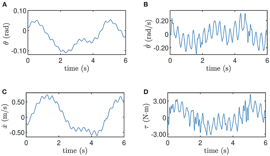
Figure 5. Training data for height = 0.33 m. (A) Pitch angle θ, (B) pitch velocity , (C) line velocity ẋ, and (D) input torque τ.
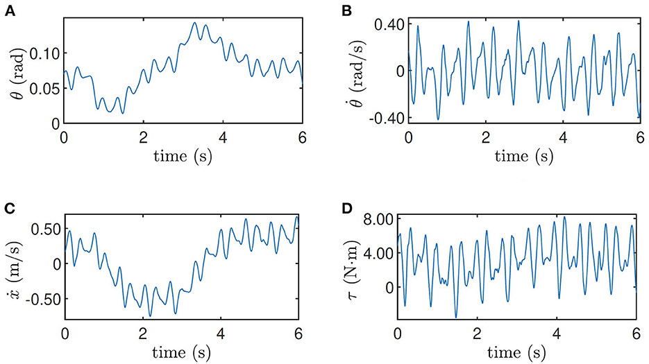
Figure 6. Training data for height = 0.5 m on the slope. (A) Pitch angle θ, (B) pitch velocity , (C) line velocity ẋ, and (D) input torque τ.
Finally, by setting Q = diag(900, 400, 150), R = 1 in Algorithm 1, the control parameters of the four training converge to
by the stopping criterion ϵ = 10−4 in 19, 18, 16, and 21 iterations, respectively (Figure 7). It should be highlighted that the fast convergence enables Algorithm 1 to be implemented online. Moreover, the robustness of the ADP-based algorithm guarantees the convergence to a small neighborhood of the optimal solution when noisy data are used (Pang et al., 2022).
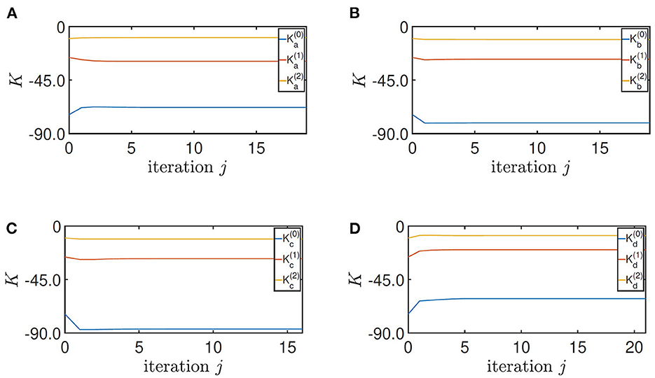
Figure 7. Convergence of the feedback gain K. (A) Height = 0.33 m, (B) height = 0.5 m, (C) height = 0.5 m with the load, and (D) height = 0.5 m on the slope.
The tuning of the parameter Q and R follows the standard process of LQR design. It is noticed in Zhang et al. (2022) and its accompanying video that the motor input is oscillating, which is caused by the overlarge regulation on the pitch angle of the robot. In this paper, the first diagonal term of Q is reduced accordingly. Moreover, by manual testing, the convergence of the algorithm is most sensitive on the third diagonal term of Q, whose feasible range is from 90 to 280. In addition, the second diagonal term of Q should be larger than 180, and the first diagonal term can be any positive value. These results indicate the robustness of the convergence of Algorithm 1 on the parameters Q and R.
4.3. Testing
In the accompanying video, the trained controllers are updated to the robot online after the data collection. Here, we compare the initial controller and the result controller of AOOR directly to avoid the effect on the visual sense caused by the movement and exploration noises in the training process.
In the first experiment, the robot is at the height 0.33 m, with experimental data given in Figure 8. The initial controller K0 is used at first, and the experimenter uses the remote controller to force the robot to stand still. Then, after releasing the remote controller, the robot moves forward continuously in the first 2 s, which is indicated by the red line in Figure 8C. Then, by enabling the updated controller with and La at t = 2 s, the robot decelerates sharply and stays still in the following 6 s, which is indicated by the blue line in Figure 8C. In order to realize the fast regulation, the motor input is a little oscillating, but the effects on the pitch angle (Figure 8A) and the linear velocity (Figure 8C) are acceptable. The still image of the testing process is shown in Figure 9A. Combining the still image and the testing data, it is clear that the average velocity when using the AOOR is much slower than the initial case, reflected by the smaller displacement during a longer time. The small displacement during the AOOR period is caused by the convergence from the initial velocity to zero, which is naturally inevitable.
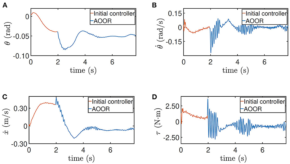
Figure 8. Testing results for height = 0.33 m. (A) Pitch angle θ, (B) pitch velocity , (C) line velocity ẋ, and (D) input torque τ.
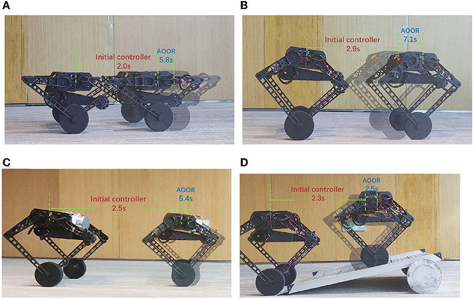
Figure 9. Still images during the testing. Many more maneuvers in action and experimental data are shown in the accompanying video. (A) Height = 0.33 m, (B) height = 0.5 m, (C) height = 0.5 m with the load, (D) height = 0.5 m on the slope.
The testing processes when the robot is at the height 0.5 m and with the load are similar. By the testing data (Figures 10, 11), the robot decelerates and stands still (ẋ → 0) after the AOOR is enabled. The small displacement, including the deceleration phase, is demonstrated in Figures 9B, C respectively.
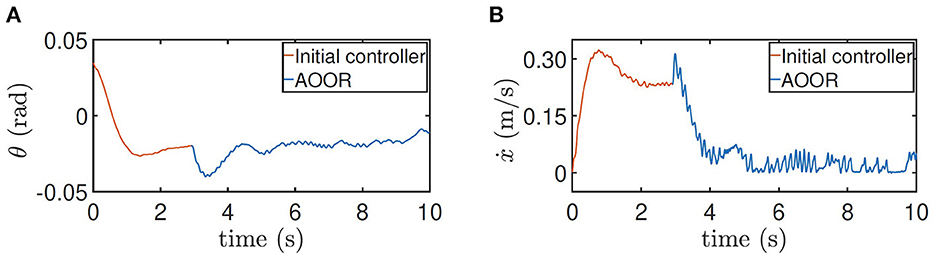
Figure 10. Testing results for height = 0.5 m. (A) Pitch angle θ. (B) line velocity ẋ.
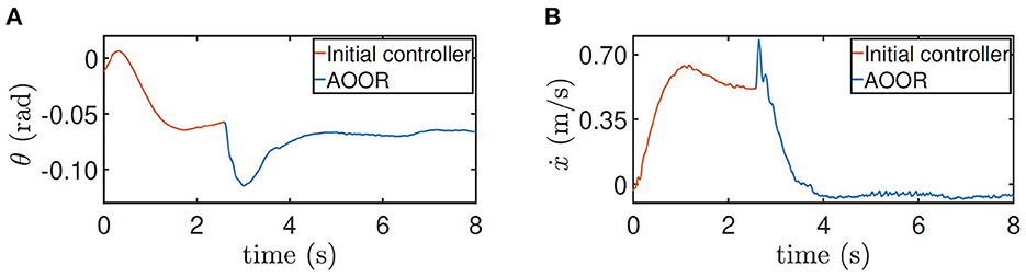
Figure 11. Testing results for height = 0.5 m with the load. (A) Pitch angle θ. (B) line velocity ẋ.
For the testing on the slope, the method is similar. The difference is that the AOOR is used in the beginning to compare with the initial control latter. The reason is that, if the initial control is used in the beginning, the robot may leave the slope quickly before enabling the AOOR. The outstanding regulation performance is indicated by the data (Figure 12) together with the still image (Figure 9D).
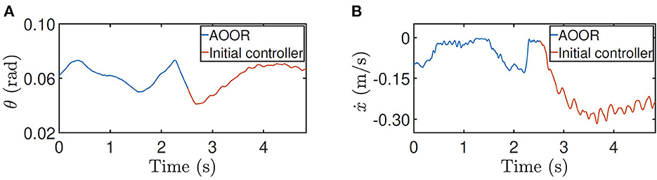
Figure 12. Testing results for height = 0.5 m on the slope. (A) Pitch angle θ. (B) line velocity ẋ.
The comparison of the controllers are summarized in Table 1. The much smaller displacement within the longer time by the AOOR indicates the strong regulation. The nonzero displacement includes the deceleration phase after enabling the AOOR, and any slight error in the regulation term L may also cause a small displacement in the steady state.

Table 1. Comparison of the controllers during the testing.
4.4. Application
The AOOR is applied when the robot is balancing a rolling cylindrical water bottle on the top. A PD controller is used to tune the floating base by the feedback of the bottle position (sb) and velocity (ṡb) with respect to the center of the floating base in the x direction by the following laws
where q(5) denotes the pitch angle of the floating base of the robot. Hence, the controller aims to regulate the ball at the target position () with the PD gain , , and to keep the floating base horizontal (q(5) = 0) wit the PD gain , . The signs depend on the positive directions of the predefined coordinates. In addition, the state sb is updated by a self-developed tactile sensor (Zhao et al., 2022) by Tencent Robotics X.
First, with the initial controller, the robot keeps moving forward as shown in Figure 13. In consequence, when the bottle is placed on the top, the overlarge relative velocity between the robot and the bottle is a destructive initial condition for the bottle balancing task. As shown in the figure, the control is not converging, and the bottle drops in 2 s.
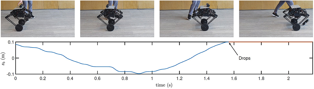
Figure 13. Still images and real-time data obtained during bottle balancing using the initial controller. Many more maneuvers in action and experimental data are shown in the accompanying video.
Next, with the AOOR, the robot almost stands still, so the ignorable relative velocity provides an ideal initial condition for the bottle balancing task. As shown in Figure 14, the bottle is controlled to the middle of the top. Combining with the mobility over complex terrains, this result shows the possibility to apply the wheel-legged robot to deliver goods for which the contact with the robot is not closed.
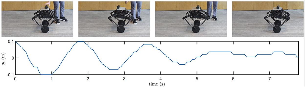
Figure 14. Still images and real-time data obtained during bottle balancing using the AOOR. Many more maneuvers in action and experimental data are shown in the accompanying video.
5. Conclusion
The mismatch between the ideal modeling in simulation and the real robot would cause the deterioration of the control performance. This is reflected in the experiments of our previous works, where the robot is balanced but cannot stand still without extra manual adjustment. Moreover, it is also troublesome to deal with the possible variations in the robot dynamics during the operation caused by both internal and external factors. To solve these problems, the idea of AOOR in the author's previous publication is applied in the balance controller design of the wheel-legged robot Ollie. In the experiments, by a training process of 6 s using the AOOR, the optimality of the controller is preserved when the working condition changes. In addition, the noticed problems in the previous works are solved, where the robot can stand still when it is at different heights. Furthermore, more challenging experiments are designed to test the AOOR-based controller by adding an eccentric heavy load to the robot, and by driving the robot on a slope. Finally, the proposed AOOR-based controller improves the success rate when the robot is balancing a cylinder water bottle on the top cover. This result makes it possible to apply the robot to deliver goods for which the limitation on the shape is relaxed.
Several feasible future studies would be interesting to further improve the control performance. In this paper, the working condition of the robot is changed during operation but is not time-varying. In the case of time-varying disturbances, it is possible to extend the AOOR algorithm to include the output regulation term that deals with time-varying disturbances. Moreover, in our previous research, the robot could be stabilized from arbitrary (unstable) input by the VI algorithm. Hence, it is also interesting to explore a VI-based AOOR algorithm to regulate the robot to its equilibrium point from arbitrary input. Finally, the robot works in its linearizable region in this work. However, for a wider working range or for more complex robotic systems, it is worth studying to extend the AOOR to nonlinear systems by combining the nonlinear ADP and nonlinear output regulation, where the computational efficiency would be a core issue.
Data availability statement
The original contributions presented in the study are included in the article/Supplementary material, further inquiries can be directed to the corresponding author.
Author contributions
JZ and ZL proposed the theory, conducted the experiment, and wrote the manuscript. SW proposed the general idea of this theory and its application to the robot. SW and YZ supervised this work and revised the manuscript. YD and JT designed and fabricated the tactile sensor on the robot. RZ designed the data collection board of the tactile sensor. JL and KC designed and integrated the hardware and embedded system of the robot. DZ designed and maintained the mechanical system of the robot. JH revised the manuscript. WG discussed the theory and revised the manuscript. All authors contributed to the article and approved the submitted version.
Acknowledgments
The authors acknowledge Leilei Cui, Prof. Zhong-Ping Jiang from New York University and Dr. Zhengyou Zhang from Tencent Robotics X for their useful suggestions and discussions, and Haitao Wang, Jiahao Wang from Tencent Robotics X for their generous help and assistance in the system integration and experiments.
Conflict of interest
JZ, ZL, SW, YD, RZ, JL, DZ, KC, and YZ are employed by Tencent Holdings.
The remaining authors declare that the research was conducted in the absence of any commercial or financial relationships that could be construed as a potential conflict of interest.
Publisher's note
All claims expressed in this article are solely those of the authors and do not necessarily represent those of their affiliated organizations, or those of the publisher, the editors and the reviewers. Any product that may be evaluated in this article, or claim that may be made by its manufacturer, is not guaranteed or endorsed by the publisher.
Supplementary material
The Supplementary Material for this article can be found online at: https://www.frontiersin.org/articles/10.3389/fnbot.2022.1102259/full#supplementary-material
References
Ackerman, E. (2021). Tencent's New Wheeled Robot Flicks Its Tail to do Backflips. IEEE Spectrum. Available online at: https://spectrum.ieee.org/tencents-new-wheeled-robot-flicks-its-tail-to-do-backflips (accessed December 22, 2022).
Ashurst, J., and Wagner, B. (2015). Injuries following segway personal transporter accidents: case report and review of the literature. Western J. Emergency Med. 16, 693. doi: 10.5811/westjem.2015.7.26549
Bian, T., and Jiang, Z.-P. (2016). Value iteration and adaptive dynamic programming for data-driven adaptive optimal control design. Automatica 71, 348–360. doi: 10.1016/j.automatica.2016.05.003
Bian, T., and Jiang, Z.-P. (2022). Reinforcement learning and adaptive optimal control for continuous-time nonlinear systems: a value iteration approach. IEEE Trans. Neural Netw. Learn. Syst. 33, 2781–2790. doi: 10.1109/TNNLS.2020.3045087
Cui, L., Wang, S., Zhang, J., Zhang, D., Lai, J., Zheng, Y., et al. (2021). Learning-based balance control of wheel-legged robots. IEEE Rob. Autom. Lett. 6, 7667–7674. doi: 10.1109/LRA.2021.3100269
Gao, W., Gao, J., Ozbay, K., and Jiang, Z.-P. (2019). Reinforcement-learning-based cooperative adaptive cruise control of buses in the lincoln tunnel corridor with time-varying topology. IEEE Trans. Intell. Transport. Syst. 20, 3796–3805. doi: 10.1109/TITS.2019.2895285
Gao, W., and Jiang, Z.-P. (2016). Adaptive dynamic programming and adaptive optimal output regulation of linear systems. IEEE Trans. Automat. Contr. 61, 4164–4169. doi: 10.1109/TAC.2016.2548662
Gao, W., and Jiang, Z.-P. (2017). Nonlinear and adaptive suboptimal control of connected vehicles: a global adaptive dynamic programming approach. J. Intell. Rob. Syst. 85, 597–611. doi: 10.1007/s10846-016-0395-3
Gao, W., and Jiang, Z.-P. (2022). Learning-based adaptive optimal output regulation of linear and nonlinear systems: an overview. Control Theory Technol. 20, 1–19. doi: 10.1007/s11768-022-00081-3
Gao, W., Jiang, Z.-P., and Ozbay, K. (2016). Data-driven adaptive optimal control of connected vehicles. IEEE Trans. Intell. Transport. Syst. 18, 1122–1133. doi: 10.1109/TITS.2016.2597279
Guo, L., Rizvi, S. A. A., and Lin, Z. (2021). Optimal control of a two-wheeled self-balancing robot by reinforcement learning. Int. J. Robust Nonlinear Control 31, 1885–1904. doi: 10.1002/rnc.5058
Huang, J. (2004). Nonlinear Output Regulation. Philadelphia, PA: Society for Industrial and Applied Mathematics.
Huang, J., Ding, F., Fukuda, T., and Matsuno, T. (2012). Modeling and velocity control for a novel narrow vehicle based on mobile wheeled inverted pendulum. IEEE Trans. Control Syst. Technol. 21, 1607–1617. doi: 10.1109/TCST.2012.2214439
Huang, M., Gao, W., Wang, Y., and Jiang, Z.-P. (2019). Data-driven shared steering control of semi-autonomous vehicles. IEEE Trans. Hum. Mach. Syst. 49, 350–361. doi: 10.1109/THMS.2019.2900409
Isidori, A., and Byrnes, C. I. (1990). Output regulation of nonlinear systems. IEEE Trans. Automat. Contr. 35, 131–140. doi: 10.1109/9.45168
Jiang, Y., and Jiang, Z.-P. (2012a). Computational adaptive optimal control for continuous-time linear systems with completely unknown dynamics. Automatica 48, 2699–2704. doi: 10.1016/j.automatica.2012.06.096
Jiang, Y., and Jiang, Z.-P. (2012b). “Robust adaptive dynamic programming for nonlinear control design,” in Proceedings of 2012 IEEE 51st IEEE Conference on Decision and Control (CDC) (Maui, HI: IEEE), 1896–1901.
Jiang, Y., and Jiang, Z.-P. (2017). Robust Adaptive Dynamic Programming. Hoboken, NJ: John Wiley Sons.
Jiang, Z.-P., and Jiang, Y. (2013). Robust adaptive dynamic programming for linear and nonlinear systems: an overview. Eur. J. Control 19, 417–425. doi: 10.1016/j.ejcon.2013.05.017
Jianwang, H., and Ramirez-Mendoza, R. A. (2022). Synthesis analysis for data driven model predictive control. Syst. Sci. Control Eng. 10, 79–89. doi: 10.1080/21642583.2022.2039321
Jung, S., and Kim, S. S. (2008). Control experiment of a wheel-driven mobile inverted pendulum using neural network. IEEE Trans. Control Syst. Technol. 16, 297–303. doi: 10.1109/TCST.2007.903396
Kleinman, D. (1968). On an iterative technique for Riccati equation computations. IEEE Trans. Automat. Contr. 13, 114–115. doi: 10.1109/TAC.1968.1098829
Klemm, V., Morra, A., Gulich, L., Mannhart, D., Rohr, D., Kamel, M., et al. (2020). LQR-assisted whole-body control of a wheeled bipedal robot with kinematic loops. IEEE Rob. Automat. Lett. 5, 3745–3752. doi: 10.1109/LRA.2020.2979625
Lauwers, T. B., Kantor, G. A., and Hollis, R. L. (2006). “A dynamically stable single-wheeled mobile robot with inverse mouse-ball drive,” in Proceedings of 2006 IEEE International Conference on Robotics and Automation, 2006. ICRA 2006 (Orlando, FL: IEEE), 2884–2889.
Lewis, F., Syrmos, V., and Syrmos, V. (1995). Optimal Control. A Wiley-Interscience Publication. New York, NY: Wiley.
Murtaza, M. A., Azimi, V., and Hutchinson, S. (2020). “Feedback whole-body control of wheeled inverted pendulum humanoids using operational space,” in Proceedings of 2020 IEEE/RSJ International Conference on Intelligent Robots and Systems (IROS) (Las Vegas, NV: IEEE), 7470–7476.
Nagarajan, U., Kim, B., and Hollis, R. (2012). “Planning in high-dimensional shape space for a single-wheeled balancing mobile robot with arms,” in Proceedings of 2012 IEEE International Conference on Robotics and Automation (Saint Paul, MN: IEEE), 130–135.
Pang, B., Bian, T., and Jiang, Z.-P. (2022). Robust policy iteration for continuous-time linear quadratic regulation. IEEE Trans. Automat. Contr. 67, 504–511. doi: 10.1109/TAC.2021.3085510
Qasem, O., Gao, W., and Bian, T. (2021). “Adaptive optimal control of continuous-time linear systems via hybrid iteration,” in Proceedings of 2021 IEEE Symposium Series on Computational Intelligence (SSCI) (Orlando, FL: IEEE), 01–07.
Raudys, A., and Šubonienė, A. (2020). “A review of self-balancing robot reinforcement learning algorithms,” in Proceedings of International Conference on Information and Software Technologies (Kaunas), 159–170.
Raza, F., Zhu, W., and Hayashibe, M. (2021). Balance stability augmentation for wheel-legged biped robot through arm acceleration control. IEEE Access 9, 54022–54031. doi: 10.1109/ACCESS.2021.3071055
Wang, S., Cui, L., Zhang, J., Lai, J., Zhang, D., Chen, K., et al. (2021). “Balance control of a novel wheel-legged robot: design and experiment,” in Proceedings of 2021 International Conference on Robotics and Automation (Xian), 6782–6788.
Willems, J. C., Rapisarda, P., Markovsky, I., and De Moor, B. L. (2005). A note on persistency of excitation. Syst. Control Lett. 54, 325–329. doi: 10.1016/j.sysconle.2004.09.003
Zafar, M., Hutchinson, S., and Theodorou, E. A. (2019). “Hierarchical optimization for whole-body control of wheeled inverted pendulum humanoids,” in Proceedings of 2019 International Conference on Robotics and Automation (ICRA) (Montreal, QC), 7535–7542.
Zambella, G., Lentini, G., Garabini, M., Grioli, G., Catalano, M. G., Palleschi, A., et al. (2019). Dynamic whole-body control of unstable wheeled humanoid robots. IEEE Rob. Automat. Lett. 4, 3489–3496. doi: 10.1109/LRA.2019.2927961
Zhang, C., Liu, T., Song, S., and Meng, M. Q.-H. (2019). “System design and balance control of a bipedal leg-wheeled robot,” in Proceedings of 2019 IEEE International Conference on Robotics and Biomimetics (ROBIO) (Dali: IEEE), 1869–1874.
Zhang, J., Wang, S., Wang, H., Lai, J., Bing, Z., Jiang, Y., et al. (2022). “An adaptive approach to whole-body balance control of wheel-bipedal robot Ollie,” in Proceedings of 2022 IEEE/RSJ International Conference on Intelligent Robots and Systems (Kyoto: IEEE).
Zhao, Z., Tang, J., Yuan, J., Li, Y., Dai, Y., Yao, J., et al. (2022). Large-scale integrated flexible tactile sensor array for sensitive smart robotic touch. ACS Nano 16, 16784–16795. doi: 10.1021/acsnano.2c06432
Zhou, H., Li, X., Feng, H., Li, J., Zhang, S., and Fu, Y. (2019). “Model decoupling and control of the wheeled humanoid robot moving in sagittal plane,” in Proceedings of 2019 IEEE-RAS 19th International Conference on Humanoid Robots (Humanoids) (Toronto, ON: IEEE), 1–6.
Keywords: optimal control, output regulation, adaptive control, data-driven control, wheel-legged robot
Citation: Zhang J, Li Z, Wang S, Dai Y, Zhang R, Lai J, Zhang D, Chen K, Hu J, Gao W, Tang J and Zheng Y (2023) Adaptive optimal output regulation for wheel-legged robot Ollie: A data-driven approach. Front. Neurorobot. 16:1102259. doi: 10.3389/fnbot.2022.1102259
Received: 18 November 2022; Accepted: 14 December 2022;
Published: 12 January 2023.
Edited by:
Tiantai Deng, The University of Sheffield, United KingdomReviewed by:
Jie Jin, Hunan University of Science and Engineering, ChinaZhu Bingjie, National University of Defense Technology, China
Ziang Li, Nanjing Tech University, China
Copyright © 2023 Zhang, Li, Wang, Dai, Zhang, Lai, Zhang, Chen, Hu, Gao, Tang and Zheng. This is an open-access article distributed under the terms of the Creative Commons Attribution License (CC BY). The use, distribution or reproduction in other forums is permitted, provided the original author(s) and the copyright owner(s) are credited and that the original publication in this journal is cited, in accordance with accepted academic practice. No use, distribution or reproduction is permitted which does not comply with these terms.
*Correspondence: Shuai Wang,  c2hhd25zaHdhbmdAdGVuY2VudC5jb20=
†These authors have contributed equally to this work and share first authorship
‡This work was done when Zhaoxiang was an intern at Tencent Robotics X