
94% of researchers rate our articles as excellent or good
Learn more about the work of our research integrity team to safeguard the quality of each article we publish.
Find out more
ORIGINAL RESEARCH article
Front. Nanotechnol., 05 February 2024
Sec. Nanomaterials
Volume 5 - 2023 | https://doi.org/10.3389/fnano.2023.1333127
This article is part of the Research TopicWomen in Nanotechnology, voIume IView all 10 articles
 Antonija Grubišić-Čabo1,2*
 Jimmy C. Kotsakidis1,3
 Yuefeng Yin4,5
 Anton Tadich5,6,7Matthew Haldon1Sean Solari1John Riley7Eric Huwald7Kevin M. Daniels8,9,10Rachael L. Myers-Ward11Mark T. Edmonds1,5Nikhil V. Medhekar4,5
 D. Kurt Gaskill9Michael S. Fuhrer1,5*
We study quasi-freestanding bilayer graphene on silicon carbide intercalated by calcium. The intercalation, and subsequent changes to the system, were investigated by low-energy electron diffraction, angle-resolved photoemission spectroscopy (ARPES) and density-functional theory (DFT). Calcium is found to intercalate only at the graphene-SiC interface, completely displacing the hydrogen terminating SiC. As a consequence, the system becomes highly n-doped. Comparison to DFT calculations shows that the band dispersion, as determined by ARPES, deviates from the band structure expected for Bernal-stacked bilayer graphene. Instead, the electronic structure closely matches AA-stacked bilayer graphene on calcium-terminated SiC, indicating a spontaneous transition from AB- to AA-stacked bilayer graphene following calcium intercalation of the underlying graphene-SiC interface.
Graphene, a single layer of graphite Novoselov et al. (2004) is notable for its unique bandstructure with massless Dirac Fermions Novoselov et al. (2005), which give rise to a plethora of exotic physical phenomena, such as a π-Berry phase Zhang et al. (2005); Liu et al. (2011); Hwang et al. (2011), Katsnelson et al. (2006) and an unusual quantum Hall effect Zhang et al. (2005).
In contrast, the most typical form of bilayer graphene, so called AB- or Bernal stacked bilayer graphene (Supplementary Figures S3A, B), has a completely different electronic structure with massive, yet gapless, Dirac fermions, and a Berry phase of 2π Ohta et al. (2006); Partoens and Peeters (2006); McCann and Koshino (2013); Novoselov et al. (2006). In principle, other types of stacking, such as AA-stacking (Supplementary Figures S3C, D), exist. AA-stacking is a metastable stacking, where graphene layers lie directly above one another. Consequently, AA-stacked graphene has an electronic structure which can be considered as a superposition of two single-layer spectra, preserving massless Dirac fermions and a π-Berry phase Liu et al. (2009); Rozhkov et al. (2016). Despite many interesting properties predicted for AA-stacked bilayer graphene, including a recent prediction that it might host a fractional metal state Sboychakov et al. (2021), there are very few experimental realisations Kim et al. (2013); Liu et al. (2009); Caffrey et al. (2016); Endo et al. (2018); de Jong et al. (2018), de Jong et al. (2023). Out of the few reported cases, the majority have been found in lithium intercalated systems Caffrey et al. (2016); Endo et al. (2018), or contained within very small regions otherwise surrounded by AB-stacked graphene de Jong et al. (2018), de Jong et al. (2023).
One of the most promising methods for graphene production in terms of scalability is the growth of graphene on silicon carbide (SiC) which allows formation of large-scale graphene with high carrier mobility Starke and Riedl (2009); Nyakiti et al. (2012); Kruskopf et al. (2016); Emtsev et al. (2009). Graphene on SiC can either be epitaxial, i.e., directly grown on the SiC, with a buffer layer in between the graphene and the SiC interface, or quasi-freestanding graphene–most commonly created via hydrogen intercalation of epitaxial graphene Daniels et al. (2017); Riedl et al. (2009), in which graphene retains the properties expected for the isolated layer Sforzini et al. (2015). Hydrogen is not the only element that can be used to create quasi-freestanding graphene on SiC by means of intercalation Briggs et al. (2019); various other elements can be used, such as gold Sohn et al. (2021); Marchenko et al. (2016), iron Sung et al. (2014); Shen et al. (2018), oxygen Oliveira et al. (2013), lithium Bao et al. (2014); Caffrey et al. (2016); Endo et al. (2018); Virojanadara et al. (2010), magnesium Kotsakidis et al. (2020); Grubišić-Čabo et al. (2021); Kotsakidis et al. (2021), calcium Kotsakidis et al. (2020); Valla et al. (2009); Yang et al. (2014); Endo et al. (2020); Toyama et al. (2022); Ichinokura et al. (2016), antimony Wolff et al. (2019) and ytterbium Watcharinyanon et al. (2013). The majority of the intercalation studies have been done on epitaxial monolayer and bilayer graphene on SiC, with very few intercalation studies on already quasi-freestanding, hydrogen intercalated, graphene Watcharinyanon et al. (2012); Kim et al. (2019); Kotsakidis et al. (2020). Of particular interest to us is calcium intercalated graphene, whose study was inspired by the bulk superconducting graphite intercalation compound CaC6 Sugawara et al. (2009); Yang et al. (2014); Weller et al. (2005); Emery et al. (2005). The majority of calcium intercalation experiments have been performed on graphene grown on SiC, as this allows for growth of large-area graphene that can be characterised with various surface characterisation techniques, such as X-ray photoelectron spectroscopy (XPS), angle-resolved photoemission spectroscopy (ARPES), low-energy electron diffraction (LEED) and scanning tunnelling microscopy Kotsakidis et al. (2020); Ohta et al. (2006); Kanetani et al. (2012); McChesney et al. (2010). Calcium intercalation is known to strongly n-type dope graphene, an effect which has been extensively studied Ohta et al. (2006); McChesney et al. (2010), however, the impact of calcium intercalation on the structural aspects of graphene and the precise positioning of calcium atoms remained somewhat ambiguous Kotsakidis et al. (2020); Ichinokura et al. (2016); Kanetani et al. (2012). Recent research using XPS by Kotsakidis et al. (2020) has shed light on this, revealing that calcium is situated at the interface between the SiC substrate and graphene buffer layer, with work by Toyama et al. (2022) further confirming that calcium prefers to go to the SiC interface.
In this paper, we report calcium intercalation of quasi-freestanding bilayer graphene (QFSBLG) on SiC. Using a combination of LEED, ARPES and density-functional theory (DFT), calcium is found to intercalate only at the interface between graphene and SiC, fully replacing hydrogen in the structure, and not between the graphene layers. This results in highly n-doped, quasi-freestanding bilayer graphene (Ca-QFSBLG) with a drastically altered electronic structure, as seen by ARPES. Comparison with DFT shows the structure to be in close agreement with AA-stacked bilayer graphene, indicating a spontaneous transition from AB- to AA-stacking, which has not been previously observed for calcium intercalated graphene.
QFSBLG samples on SiC were grown on semi-insulating 6H-SiC(0001) substrate as described in Ref. Daniels et al. (2017). Sample preparation, ARPES and LEED measurements were carried out at the Toroidal Analyzer endstation at the Soft X-ray Beamline of the Australian Synchrotron. Samples were introduced to ultra-high vacuum (UHV, base pressure of 1 × 10⁻¹⁰ mbar), and annealed over night at 773–823 K. Sample cleanliness was confirmed by LEED and ARPES. A calcium effusion cell was baked at 423 K overnight and outgassed at 588 K. Once the pressure reached 1 × 10⁻⁸ mbar, the effusion cell was inserted into the UHV preparation chamber. Calcium (dendritic pieces, 99.99%, Sigma-Aldrich) was intercalated under graphene following modified recipe from Ref. Kotsakidis et al. (2020): Calcium was evaporated for 15 min, with the calcium cell held at 688 K, and deposited on the graphene/SiC substrate held at room temperature. The thickness of deposited calcium layer was 22 Å, as determined by a quartz crystal microbalance. Following the deposition, the graphene/SiC substrate was annealed at 773 K for 15 min, in order to facilitate calcium intercalation.
Structural characterisation of samples was undertaken using a LEED (OCIVM 3 grid reverse view optics, 200 μm spot size) at room temperature, in the endstation used for ARPES. ARPES measurements used a toroidal-type angle-resolving endstation Broekman et al. (2005) at the Soft X-Ray Beamline of the Australian Synchrotron. All ARPES data was taken at room temperature with photon energy (hν) of 100 eV using linearly polarised light at normal incidence to the sample. The beam spot size was 100 μm × 60 μm. The binding energy (EBin) scale for all spectra is referenced to the Fermi energy (EF), determined using the Fermi edge of a gold foil reference sample in electrical contact with the sample. The toroidal analyser permits all polar (Θ) emission angles (−90° to +90°) to be measured along a high-symmetry azimuth (ϕ) of the surface containing the
First principles density-functional theory calculations were implemented using the Vienna ab initio Simulation Package (VASP) to calculate the electronic structure of Ca-QFSBLG Kresse and Furthmüller (1996). The Perdew-Burke-Ernzehof (PBE) form of the generalized gradient approximation (GGA) was used to describe electron exchange and correlation Perdew et al. (1996). A semi-empirical functional (DFT-D2) was employed to describe van der Waals interactions in the system Grimme et al. (2011). The kinetic energy cut-off for the plane-wave basis set was set to 500 eV. We used a 9 × 9 × 1 Γ-centred k-point mesh for sampling the Brillouin zone. The unfolded band structure and Fermi surface were obtained using the KPROJ program based on the k-projection method Chen and Weinert (2018); Chen et al. (2017). Tight-binding calculations were performed in Igor Pro Wavemetrics software based on Ref. Rozhkov et al. (2016) for AA-stacked bilayer graphene, and Refs. Partoens and Peeters (2006); McCann and Koshino (2013) for AB-stacked bilayer graphene. Tight-binding calculations are presented along the
QFSBLG samples, Figure 1A, prepared as described in Ref. Daniels et al. (2017) were loaded into the UHV chamber and annealed to remove surface adsorbates, as described in Methods. Following the annealing procedure, LEED data was taken on the clean sample, as shown in Figure 1C. LEED data shows typical diffraction pattern of quasi-freestanding graphene, with only (1 × 1) graphene spots (red circles) and (1 × 1) SiC spots rotated 30° with respect to graphene (purple circles) visible. Following calcium intercalation (Figure 1B), the SiC (1 × 1) spots are less intense compared to the clean QFSBLG, but no other significant changes can be seen in LEED, as shown in Figure 1D. After the second intercalation step (Figure 1E) drastic changes can be observed in the LEED pattern: (1 × 1) SiC spots are almost completely gone, while (1 × 1) graphene spots are much weaker and broader. Blurring of the graphene (1 × 1) spots suggests additional scattering, likely from calcium atoms accumulating on the surface of the sample in a disordered manner. A new feature can also be observed in the diffraction pattern in Figure 1E, a diffuse ring, marked by a yellow arrow, with a radius corresponding to that of a
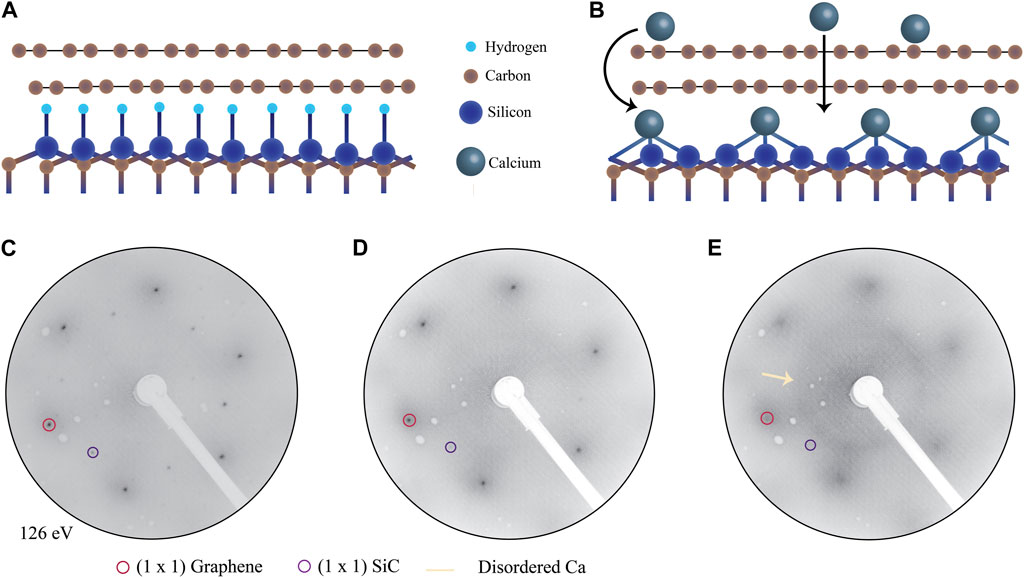
FIGURE 1. Quasi freestanding bilayer graphene (QFSBLG) before and after calcium intercalation. A sketch of QFSBLG before and after intercalation, where hydrogen is replaced by calcium at the SiC interface is shown in (A,B), respectively. (C) LEED image of QFSBLG prior calcium intercalation, (D) following first, and (E) following second calcium intercalation. Red circles indicate the (1 × 1) graphene spots, purple circles indicate the (1 × 1) SiC spots. Yellow arrow points to the ring arising from disordered Ca. All data taken at an incident beam energy of 126 eV and room temperature.
Following structural characterization by LEED, we proceed with the electronic structure investigation using ARPES Damascelli (2004) which allows direct imaging of the electronic bands. Due to an increase in observed disorder for the second intercalation step in LEED (Figure 1E) we will only focus on the first intercalation step for the ARPES investigation. Figure 2 shows intercalation induced changes in the electronic structure of graphene, as observed by ARPES. Changes are tracked in the energy–momentum cuts taken at the Fermi surface (Figures 2A, C) and along the
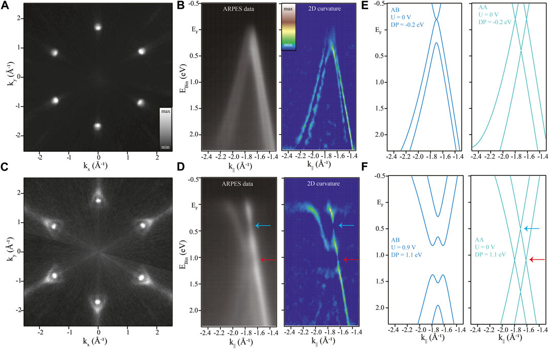
FIGURE 2. ARPES measurements of clean and calcium intercalated quasi-freestanding bilayer graphene (Ca-QFSBLG) after the first intercalation step. (A) Fermi surface and (B) band structure around the
Upon calcium intercalation, profound changes can be observed in the electronic structure: two sets of electron pockets can be seen at the Fermi surface (Figure 2C), and system exhibits high levels of n-doping (Figure 2D). In order to better understand the dispersions and changes arising from calcium intercalation, we compare our experimental data to simple tight-binding models for AA- and AB-stacked graphene (Figures 2E, F) Rozhkov et al. (2016); Partoens and Peeters (2006). The same model was used to estimate Dirac point position, doping, Fermi wavevector and Fermi velocity. We used the band position data obtained from momentum dispersion curves, to refine the tight-binding model, and select the appropriate graphene stacking. More information about this can be found in the Supplementary Material. Prior to calcium intercalation, the system is found to be p-doped, with the Dirac point located at DP = (0.20 ± 0.02) eV above the Fermi level, and a Fermi wavevector (kF) value of kF = (0.057 ± 0.007) Å−1, corresponding to a hole carrier density of
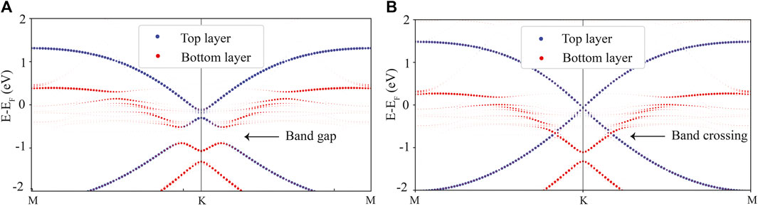
FIGURE 3. DFT calculations for calcium intercalated QFSBLG. The unfolded band structure of calcium intercalated bilayer graphene for the case of AB- and AA-stacking is shown in (A) and (B), respectively. The contribution from the top graphene layer is shown in blue, and from the bottom layer in red. Arrows indicate a band gap for the case of AB-stacking, (A), and a band crossing for the case of AA-stacking in Ca-QFSBLG, (B).
We further examine the nature of stacking in Ca-QFSBLG by performing DFT calculations of the electronic structure of AB- and AA-stacked Ca-QFSBLG. We first calculate the calcium intercalation energy based on Eq. 1 as follows:
where EI is the intercalation energy, E (SiC/graphene), E (Ca) and E (SiC/graphene + Ca) are the energy of SiC/graphene heterostructure (SiC covalently bonded with graphene plus a monolayer graphene), atomic energy of calcium in its bulk state, and the energy of SiC/graphene system upon calcium intercalation, respectively. Once calcium is placed below bilayer graphene, a small difference is found in the formation energy between the AA- and AB-stacked bilayer graphene, as shown in Table 1, with AB-stacking being slightly favourable. This small difference in formation energy suggests it is plausible that AA-stacking could indeed be a stable phase in Ca-QFSBLG, similar to what has been observed for the case of lithium intercalation Watcharinyanon et al. (2012); Caffrey et al. (2016). As both structures appear energetically stable, and are close in the formation energy, DFT band structure calculations were performed for AA- and AB-stacking in order to determine which structure fits experimental ARPES data better.
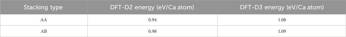
TABLE 1. Calculation for intercalation energy, AA- vs. AB-stacking, using different van der Waals corrections.
The unfolded band structure of AA- and AB-stacked Ca-QFSBLG is shown in Figure 3. For the case of AB-stacked Ca-QFSBLG (Figure 3A), a large band gap, approximately 0.38 eV in size, is found between the top of the valence band and bottom of a conduction band, situated 0.51 eV below the Fermi level. This structure is similar to the one observed for magnesium intercalated graphene on SiC Grubišić-Čabo et al. (2021), where a band gap of 0.36 eV was observed. In the case of AA-stacked bilayer graphene (Figure 3B), the structure is markedly different, and no band gap is found between the top of the valence band and bottom of a conduction band. Instead, a smaller 0.20 eV gap is identified 1.05 eV below the Fermi level located only in the bottom graphene layer. In contrast, the top graphene layer is gapless, and nearly indistinguishable from the pristine monolayer graphene. The latter structure is in good agreement with the experimental data shown in Figure 2, particularly in the region where the top- and bottom-layer derived bands cross at finite momentum (red arrows in Figures 2D, F) and the Dirac point of the top graphene layer (blue arrows in Figures 2D, F), in agreement with our experimental ARPES results which show Ca-QFSBLG as AA-stacked.
The interaction distance between intercalated calcium atoms and graphene plays a crucial role in driving the electronic structure differences between AA-stacked and AB-stacked systems. In the AA-stacked system with calcium intercalation, we observed a larger separation between the graphene layers and calcium atoms for AA-stacked configuration (2.45 Å) in comparison to the AB-stacked configuration (2.33 Å, Supplementary Figure S3). This observation may provide a partial explanation for the diminished impact on the top layer during the doping process.
Calcium intercalation was successfully achieved in quasi-freestanding bilayer graphene on hydrogenated SiC, resulting in significant changes to the system. Upon calcium intercalation, calcium replaced hydrogen at the SiC interface, leading to a switch from p-type doping to n-type doping. This transition was accompanied with almost two orders of magnitude change in the carrier concentration, going from
The datasets presented in this study can be found in online repositories. The names of the repository/repositories and accession number(s) can be found below: Zenodo: https://doi.org/10.5281/zenodo.10071225.
AG-C: Formal Analysis, Investigation, Visualization, Writing–original draft, Writing–review and editing, Conceptualization. JK: Conceptualization, Investigation, Writing–review and editing. YY: Formal Analysis, Writing–review and editing. AT: Data curation, Formal Analysis, Investigation, Resources, Software, Writing–review and editing. MH: Investigation, Writing–review and editing. SS: Investigation, Writing–review and editing. JR: Data curation, Resources, Writing–review and editing. EH: Resources, Writing–review and editing. KD: Resources, Writing–review and editing. RM-W: Resources, Writing–review and editing. ME: Investigation, Supervision, Writing–review and editing. NM: Formal Analysis, Supervision, Writing–review and editing. DG: Resources, Supervision, Writing–review and editing. MF: Conceptualization, Funding acquisition, Supervision, Writing–original draft, Writing–review and editing, Project administration.
The author(s) declare financial support was received for the research, authorship, and/or publication of this article. This work was supported by the Australian Research Council under awards DP150103837, DP200101345 and FL120100038. JK was supported by the Australian Government Research Training Program, and the Monash Centre for Atomically Thin Materials. YY and NM were supported by the Australian Research Council (CE17010039). DG, RM-W, and KD were supported by core programs at the U.S. Naval Research Laboratory funded by the Office of Naval Research.
This research was undertaken on the Soft X-ray spectroscopy beamline at the Australian Synchrotron, part of ANSTO. YY and NM gratefully acknowledge the computational support from the National Computing Infrastructure and Pawsey Supercomputing Facilities. Preprint version of this article was published on arXiv repository as Grubišić-Čabo et al. (2023).
The authors declare that the research was conducted in the absence of any commercial or financial relationships that could be construed as a potential conflict of interest.
All claims expressed in this article are solely those of the authors and do not necessarily represent those of their affiliated organizations, or those of the publisher, the editors and the reviewers. Any product that may be evaluated in this article, or claim that may be made by its manufacturer, is not guaranteed or endorsed by the publisher.
The Supplementary Material for this article can be found online at: https://www.frontiersin.org/articles/10.3389/fnano.2023.1333127/full#supplementary-material
Bao, W., Wan, J., Han, X., Cai, X., Zhu, H., Kim, D., et al. (2014). Approaching the limits of transparency and conductivity in graphitic materials through lithium intercalation. Nat. Commun. 5, 4224. doi:10.1038/ncomms5224
Briggs, N., Gebeyehu, Z. M., Vera, A., Zhao, T., Wang, K., De La Fuente Duran, A., et al. (2019). Epitaxial graphene/silicon carbide intercalation: a minireview on graphene modulation and unique 2D materials. Nanoscale 11, 15440–15447. doi:10.1039/C9NR03721G
Broekman, L., Tadich, A., Huwald, E., Riley, J., Leckey, R., Seyller, T., et al. (2005). First results from a second generation toroidal electron spectrometer. J. Electron Spectrosc. Relat. Phenom. 144-147, 1001–1004. doi:10.1016/j.elspec.2005.01.022
Caffrey, N. M., Johansson, L. I., Xia, C., Armiento, R., Abrikosov, I. A., and Jacobi, C. (2016). Structural and electronic properties of Li-intercalated graphene on SiC(0001). Phys. Rev. B 93, 195421. doi:10.1103/PhysRevB.93.195421
Chen, M., and Weinert, M. (2018). Layer k-projection and unfolding electronic bands at interfaces. Phys. Rev. B 98, 245421. doi:10.1103/PhysRevB.98.245421
Chen, M. X., Chen, W., Zhang, Z., and Weinert, M. (2017). Effects of magnetic dopants in Li0.8M0.2OH FeSe (M=Fe, Mn, Co): density functional theory study using a band unfolding technique. Phys. Rev. B 96, 245111. doi:10.1103/PhysRevB.96.245111
Damascelli, A. (2004). Probing the electronic structure of complex systems by ARPES. Phys. Scr. T109, 61. doi:10.1238/Physica.Topical.109a00061
Daniels, K. M., Jadidi, M. M., Sushkov, A. B., Nath, A., Boyd, A. K., Sridhara, K., et al. (2017). Narrow plasmon resonances enabled by quasi-freestanding bilayer epitaxial graphene. 2D Mat. 4, 025034. doi:10.1088/2053-1583/aa5c75
de Jong, T. A., Krasovskii, E. E., Ott, C., Tromp, R. M., van der Molen, S. J., and Jobst, J. (2018). Intrinsic stacking domains in graphene on silicon carbide: a pathway for intercalation. Phys. Rev. Mat. 2, 104005. doi:10.1103/PhysRevMaterials.2.104005
de Jong, T. A., Visser, L., Jobst, J., Tromp, R. M., and van der Molen, S. J. (2023). Stacking domain morphology in epitaxial graphene on silicon carbide. Phys. Rev. Mat. 7, 034001. doi:10.1103/PhysRevMaterials.7.034001
Elias, D. C., Gorbachev, R. V., Mayorov, A. S., Morozov, S. V., Zhukov, A. A., Blake, P., et al. (2011). Dirac cones reshaped by interaction effects in suspended graphene. Nat. Phys. 7, 701–704. doi:10.1038/nphys2049
Emery, N., Hérold, C., d’Astuto, M., Garcia, V., Bellin, C., Marêché, J. F., et al. (2005). Superconductivity of bulk CaC6. Phys. Rev. Lett. 95, 087003. doi:10.1103/PhysRevLett.95.087003
Emtsev, K. V., Bostwick, A., Horn, K., Jobst, J., Kellogg, G. L., Ley, L., et al. (2009). Towards wafer-size graphene layers by atmospheric pressure graphitization of silicon carbide. Nat. Mat. 8, 203–207. doi:10.1038/nmat2382
Emtsev, K. V., Speck, F., Seyller, T., Ley, L., and Riley, J. D. (2008). Interaction, growth, and ordering of epitaxial graphene on SiC{0001} surfaces: a comparative photoelectron spectroscopy study. Phys. Rev. B 77, 155303. doi:10.1103/PhysRevB.77.155303
Endo, Y., Fukaya, Y., Mochizuki, I., Takayama, A., Hyodo, T., and Hasegawa, S. (2020). Structure of superconducting Ca-intercalated bilayer graphene/SiC studied using total-reflection high-energy positron diffraction. Carbon 157, 857–862. doi:10.1016/j.carbon.2019.10.070
Endo, Y., Ichinokura, S., Akiyama, R., Takayama, A., Sugawara, K., Nomura, K., et al. (2018). Weak localization in bilayer graphene with Li-intercalation/desorption. J. Phys. Condens. Matter. 30, 305701. doi:10.1088/1361-648x/aaccc4
Grimme, S., Ehrlich, S., and Goerigk, L. (2011). Effect of the damping function in dispersion corrected density functional theory. J. Comput. Chem. 32, 1456–1465. doi:10.1002/jcc.21759
Grubišić-Čabo, A., Kotsakidis, J. C., Yin, Y., Tadich, A., Haldon, M., Solari, S., et al. (2021). Magnesium-intercalated graphene on SiC: highly n-doped air-stable bilayer graphene at extreme displacement fields. Appl. Surf. Sci. 541, 148612. doi:10.1016/j.apsusc.2020.148612
Grubišić-Čabo, A., Kotsakidis, J. C., Yin, Y., Tadich, A., Haldon, M., Solari, S., et al. (2023). Quasi-free-standing AA-stacked bilayer graphene induced by calcium intercalation of the graphene-silicon carbide interface. arXiv. 2311.02528.
Hwang, C., Park, C.-H., Siegel, D. A., Fedorov, A. V., Louie, S. G., and Lanzara, A. (2011). Direct measurement of quantum phases in graphene via photoemission spectroscopy. Phys. Rev. B 84, 125422. doi:10.1103/PhysRevB.84.125422
Hwang, C., Siegel, D. A., Mo, S.-K., Regan, W., Ismach, A., Zhang, Y., et al. (2012). Fermi velocity engineering in graphene by substrate modification. Sci. Rep. 2, 590. doi:10.1038/srep00590
Ichinokura, S., Sugawara, K., Takayama, A., Takahashi, T., and Hasegawa, S. (2016). Superconducting calcium-intercalated bilayer graphene. ACS Nano 10, 2761–2765. doi:10.1021/acsnano.5b07848
Kanetani, K., Sugawara, K., Sato, T., Shimizu, R., Iwaya, K., Hitosugi, T., et al. (2012). Ca intercalated bilayer graphene as a thinnest limit of superconducting C6Ca. PNAS 109, 19610–19613. doi:10.1073/pnas.1208889109
Katsnelson, M. I., Novoselov, K. S., and Geim, A. K. (2006). Chiral tunnelling and the Klein paradox in graphene. Nat. Phys. 2, 620–625. doi:10.1038/nphys384
Kim, H., Dugerjav, O., Lkhagvasuren, A., and Seo, J. M. (2019). Doping modulation of quasi-free-standing monolayer graphene formed on SiC(0001) through Sn1−xGex intercalation. Carbon 144, 549–556. doi:10.1016/j.carbon.2018.12.084
Kim, K. S., Warlter, A. L., Moreschini, L., Seyller, T., Horn, K., Rotenberg, E., et al. (2013). Coexisting massive and massless Dirac fermions in symmetry-broken bilayer graphene. Nat. Mat. 12, 887–892. doi:10.1038/nmat3717
Kotsakidis, J. C., Currie, M., Grubišić-Čabo, A., Tadich, A., Myers-Ward, R. L., DeJarld, M., et al. (2021). Increasing the rate of magnesium intercalation underneath epitaxial graphene on 6H-SiC(0001). Adv. Mat. Interfaces 8, 2101598. doi:10.1002/admi.202101598
Kotsakidis, J. C., Grubišić-Čabo, A., Yin, Y., Tadich, A., Myers-Ward, R. L., DeJarld, M., et al. (2020). Freestanding n-doped graphene via intercalation of calcium and magnesium into the buffer layer–SiC(0001) interface. Chem. Mat. 32, 6464–6482. doi:10.1021/acs.chemmater.0c01729
Kresse, G., and Furthmüller, J. (1996). Efficiency of ab-initio total energy calculations for metals and semiconductors using a plane-wave basis set. Comput. Mat. Sci. 6, 15–50. doi:10.1016/0927-0256(96)00008-0
Kruskopf, M., Pakdehi, D. M., Pierz, K., Wundrack, S., Stosch, R., Dziomba, T., et al. (2016). Comeback of epitaxial graphene for electronics: large-area growth of bilayer-free graphene on SiC. 2D Mat. 3, 041002. doi:10.1088/2053-1583/3/4/041002
Li, G., Luican, A., Lopes dos Santos, J. M. B., Castro Neto, A. H., Reina, A., Kong, J., et al. (2010). Observation of van Hove singularities in twisted graphene layers. Nat. Phys. 6, 109–113. doi:10.1038/nphys1463
Liu, Y., Bian, G., Miller, T., and Chiang, T.-C. (2011). Visualizing electronic chirality and Berry phases in graphene systems using photoemission with circularly polarized light. Phys. Rev. Lett. 107, 166803. doi:10.1103/PhysRevLett.107.166803
Liu, Z., Suenaga, K., Harris, P. J. F., and Iijima, S. (2009). Open and closed edges of graphene layers. Phys. Rev. Lett. 102, 015501. doi:10.1103/PhysRevLett.102.015501
Marchenko, D., Varykhalov, A., Sánchez-Barriga, J., Seyller, T., and Rader, O. (2016). Rashba splitting of 100 meV in Au-intercalated graphene on SiC. Appl. Phys. Lett. 108, 172405. doi:10.1063/1.4947286
Mazin, I., and Balatsky, A. (2010). Superconductivity in Ca-intercalated bilayer graphene. Philos. Mag. Lett. 90, 731–738. doi:10.1080/09500839.2010.487473
McCann, E., and Koshino, M. (2013). The electronic properties of bilayer graphene. Rep. Prog. Phys. 76, 056503. doi:10.1088/0034-4885/76/5/056503
McChesney, J. L., Bostwick, A., Ohta, T., Seyller, T., Horn, K., González, J., et al. (2010). Extended van Hove singularity and superconducting instability in doped graphene. Phys. Rev. Lett. 104, 136803. doi:10.1103/PhysRevLett.104.136803
Novoselov, K., Geim, A., Morozov, S., Jiang, D., Zhang, Y., Dubonos, S., et al. (2004). Electric field effect in atomically thin carbon films. Science 80, 306666–306669. doi:10.1126/science.1102896
Novoselov, K. S., Geim, A. K., Morozov, S. V., Jiang, D., Katsnelson, M. I., Grigorieva, I. V., et al. (2005). Two-dimensional gas of massless Dirac fermions in graphene. Nature 438, 197–200. doi:10.1038/nature04233
Novoselov, K. S., McCann, E., Morozov, S. V., Fal’ko, V. I., Katsnelson, M. I., Zeitler, U., et al. (2006). Unconventional quantum Hall effect and Berry’s phase of 2π in bilayer graphene. Nat. Phys. 2, 177–180. doi:10.1038/nphys245
Nyakiti, L., Wheeler, V., Garces, N., Myers-Ward, R., Eddy, C., and Gaskill, D. (2012). Enabling graphene-based technologies: toward wafer-scale production of epitaxial graphene. MRS Bull. 37, 1149–1157. doi:10.1557/mrs.2012.180
Ohta, T., Bostwick, A., Seyller, T., Horn, K., and Rotenberg, E. (2006). Controlling the electronic structure of bilayer graphene. Science 313, 951–954. doi:10.1126/science.1130681
Oliveira, M. H., Schumann, T., Fromm, F., Koch, R., Ostler, M., Ramsteiner, M., et al. (2013). Formation of high-quality quasi-free-standing bilayer graphene on SiC(0001) by oxygen intercalation upon annealing in air. Carbon 52, 83–89. doi:10.1016/j.carbon.2012.09.008
Partoens, B., and Peeters, F. M. (2006). From graphene to graphite: electronic structure around the K point. Phys. Rev. B 74, 075404. doi:10.1103/PhysRevB.74.075404
Perdew, J. P., Burke, K., and Ernzerhof, M. (1996). Generalized gradient approximation made simple. Phys. Rev. Lett. 77, 3865–3868. doi:10.1103/PhysRevLett.77.3865
Riedl, C., Coletti, C., Iwasaki, T., Zakharov, A. A., and Starke, U. (2009). Quasi-free-standing epitaxial graphene on SiC obtained by hydrogen intercalation. Phys. Rev. Lett. 103, 246804. doi:10.1103/PhysRevLett.103.246804
Rozhkov, A., Sboychakov, A., Rakhmanov, A., and Nori, F. (2016). Electronic properties of graphene-based bilayer systems. Phys. Rep. 648, 1–104. doi:10.1016/j.physrep.2016.07.003
Sboychakov, A. O., Rakhmanov, A. L., Rozhkov, A. V., and Nori, F. (2021). Bilayer graphene can become a fractional metal. Phys. Rev. B 103, L081106. doi:10.1103/PhysRevB.103.L081106
Sforzini, J., Nemec, L., Denig, T., Stadtmüller, B., Lee, T.-L., Kumpf, C., et al. (2015). Approaching truly freestanding graphene: the structure of hydrogen-intercalated graphene on 6H-SiC(0001). Phys. Rev. Lett. 114, 106804. doi:10.1103/PhysRevLett.114.106804
Shen, K., Sun, H., Hu, J., Hu, J., Liang, Z., Li, H., et al. (2018). Fabricating quasi-free-standing graphene on a SiC(0001) surface by steerable intercalation of iron. J. Phys. Chem. C 122, 21484–21492. doi:10.1021/acs.jpcc.8b06789
Sohn, Y., Shin, W. J., Ryu, S. H., Huh, M., Cha, S., and Kim, K. S. (2021). Graphene p-n junction formed on SiC(0001) by Au intercalation. J. Korean Phys. Soc. 78, 40–44. doi:10.1007/s40042-020-00010-0
Starke, U., and Riedl, C. (2009). Epitaxial graphene on SiC(0001) and SiC(0001-): from surface reconstructions to carbon electronics. J. Condens. Matter Phys. 21, 134016. doi:10.1088/0953-8984/21/13/134016
Sugawara, K., Sato, T., and Takahashi, T. (2009). Fermi-surface-dependent superconducting gap in C6Ca. Nat. Phys. 5, 40–43. doi:10.1038/nphys1128
Sung, S. J., Yang, J. W., Lee, P. R., Kim, J. G., Ryu, M. T., Park, H. M., et al. (2014). Spin-induced band modifications of graphene through intercalation of magnetic iron atoms. Nanoscale 6, 3824–3829. doi:10.1039/C3NR04178F
Toyama, H., Akiyama, R., Ichinokura, S., Hashizume, M., Iimori, T., Endo, Y., et al. (2022). Two-dimensional superconductivity of Ca-intercalated graphene on SiC: vital role of the interface between monolayer graphene and the substrate. ACS Nano 16, 3582–3592. doi:10.1021/acsnano.1c11161
Valla, T., Camacho, J., Pan, Z.-H., Fedorov, A. V., Walters, A. C., Howard, C. A., et al. (2009). Anisotropic electron-phonon coupling and dynamical nesting on the graphene sheets in superconducting CaC6 using angle-resolved photoemission spectroscopy. Phys. Rev. Lett. 102, 107007. doi:10.1103/PhysRevLett.102.107007
Virojanadara, C., Watcharinyanon, S., Zakharov, A. A., and Johansson, L. I. (2010). Epitaxial graphene on 6H-SiC and Li intercalation. Phys. Rev. B 82, 205402. doi:10.1103/PhysRevB.82.205402
Watcharinyanon, S., Johansson, L., Zakharov, A. A., and Virojanadara, C. (2012). Studies of Li intercalation of hydrogenated graphene on SiC(0001). Surf. Sci. 606, 401–406. doi:10.1016/j.susc.2011.10.023
Watcharinyanon, S., Johansson, L. I., Xia, C., and Virojanadara, C. (2013). Ytterbium oxide formation at the graphene–SiC interface studied by photoemission. J. Vac. Sci. Technol. A 31, 020606. doi:10.1116/1.4792040
Weller, T. E., Ellerby, M., Saxena, S. S., Smith, R. P., and Skipper, N. T. (2005). Superconductivity in the intercalated graphite compounds C6Yb and C6Ca. Nat. Phys. 1, 39–41. doi:10.1038/nphys0010
Wolff, S., Roscher, S., Timmermann, F., Daniel, M. V., Speck, F., Wanke, M., et al. (2019). Quasi-freestanding graphene on SiC(0001) by Ar-mediated intercalation of antimony: a route toward intercalation of high-vapor-pressure elements. Ann. Phys. 531, 1900199. doi:10.1002/andp.201900199
Yang, S.-L., Sobota, J. A., Howard, C. A., Pickard, C. J., Hashimoto, M., Lu, D. H., et al. (2014). Superconducting graphene sheets in CaC6 enabled by phonon-mediated interband interactions. Nat. Commun. 5, 3493. doi:10.1038/ncomms4493
Zhang, P., Richard, P., Qian, T., Xu, Y.-M., Dai, X., and Ding, H. (2011). A precise method for visualizing dispersive features in image plots. Rev. Sci. Instrum. 82, 043712. doi:10.1063/1.3585113
Keywords: graphene, calcium, intercalation, electronic structure, ARPES, DFT
Citation: Grubišić-Čabo A, Kotsakidis JC, Yin Y, Tadich A, Haldon M, Solari S, Riley J, Huwald E, Daniels KM, Myers-Ward RL, Edmonds MT, Medhekar NV, Gaskill DK and Fuhrer MS (2024) Quasi-freestanding AA-stacked bilayer graphene induced by calcium intercalation of the graphene-silicon carbide interface. Front. Nanotechnol. 5:1333127. doi: 10.3389/fnano.2023.1333127
Received: 04 November 2023; Accepted: 21 December 2023;
Published: 05 February 2024.
Edited by:
Estela Blaisten-Barojas, George Mason University, United StatesReviewed by:
Erick Ulin-Avila, Center for Engineering and Development CIDESI, MexicoCopyright © 2024 Grubišić-Čabo, Kotsakidis, Yin, Tadich, Haldon, Solari, Riley, Huwald, Daniels, Myers-Ward, Edmonds, Medhekar, Gaskill and Fuhrer. This is an open-access article distributed under the terms of the Creative Commons Attribution License (CC BY). The use, distribution or reproduction in other forums is permitted, provided the original author(s) and the copyright owner(s) are credited and that the original publication in this journal is cited, in accordance with accepted academic practice. No use, distribution or reproduction is permitted which does not comply with these terms.
*Correspondence: Antonija Grubišić-Čabo, YS5ncnViaXNpYy1jYWJvQHJ1Zy5ubA==; Michael S. Fuhrer, bWljaGFlbC5mdWhyZXJAbW9uYXNoLmVkdQ==
Disclaimer: All claims expressed in this article are solely those of the authors and do not necessarily represent those of their affiliated organizations, or those of the publisher, the editors and the reviewers. Any product that may be evaluated in this article or claim that may be made by its manufacturer is not guaranteed or endorsed by the publisher.
Research integrity at Frontiers
Learn more about the work of our research integrity team to safeguard the quality of each article we publish.