 Nicklaus Carter1,2
 Mary Bourque
 David J. Neivandt
95% of researchers rate our articles as excellent or good
Learn more about the work of our research integrity team to safeguard the quality of each article we publish.
Find out more
ORIGINAL RESEARCH article
Front. Nanotechnol. , 06 December 2021
Sec. Biomedical Nanotechnology
Volume 3 - 2021 | https://doi.org/10.3389/fnano.2021.729743
This article is part of the Research Topic Advances in Nanotechnology for Bioimaging and Medical Imaging Applications View all 4 articles
Cellulose nanomaterials are produced employing a multitude of methodologies including electrospinning, bacterial generation, acid digestion, and a variety of mechanical defibrillation techniques; the morphology of the nanomaterial produced is specific to the production process. Feedstocks range from various forms of woody biomass, to fungi, and have a great impact on the resulting product. The mechanical defibrillation technique, such as that employed in the present work, continuously breaks down cellulose fibers suspended in water via segmentation and defibrillation through grinding and refining. The process is typically operated until a desired level of fines is achieved in the resultant slurry of cellulose nanofiber (CNF), alternatively known as cellulose nanofibril. Mechanical defibrillation processes can be built to produce several liters in a small batch system or up to tons per day in a continuous pilot scale refiner system. In the present work a continuous system was developed with the capacity to produce 14 L of cellulose nanofiber slurry with consistent specifications and in a manner compliant with GMP/GLP protocols in order to be amenable to biomedical applications. The system was constructed within an ISO class 7 cleanroom and refining was performed on bleached softwood pulp suspension in purified water. This manuscript details the continuous grinding system, the processes employed to produce cellulose nanofiber, and characterizes the resultant cellulose nanofiber slurry and sheets formed from the slurry.
Cellulosic nanomaterials are finding exponentially increasing popularity from a research and development, as well as a pre-commercialization, perspective (Trache et al., 2020). The term cellulose nanomaterial refers to a variety of cellulose-based materials with at least one dimension on the nanoscale. Indeed the term is typically employed in reference to cellulosic materials composed of crystalline and/or amorphous regions with fiber diameters less than 100 nm and fiber lengths less than or equal to several microns (Mokhena and John 2020). Sub-classification of cellulose nanomaterials is often performed based on the physical characteristics of the fibrous material, which is in turn heavily influenced by the production process employed. Four classes of cellulose nanomaterials are commonly recognized: cellulose nanofiber (CNF), cellulose nanocrystals (CNC), bacterial nanocellulose, and electrospun nanocellulose. Cellulose nanofibers (CNF), alternatively known as cellulose nanofibrils have diameters ranging from 5 to 30 nm with lengths that can approach several microns. CNF is commonly confused with the slightly larger diameter microfibrillated cellulose, MFC (Moon, Schueneman, and Simonsen 2016; Tayeb et al., 2018). Cellulose nanofibers are produced through mechanical and/or chemical means (Nechyporchuk et al., 2016) with incorporation of a variety of optional pretreatments; the end products contain both amorphous and crystalline regions and tends to comprise a hierarchy of interconnected fiber sizes (Hsieh 2018). Cellulose nanocrystals (CNC), conversely are highly crystalline with a characteristic whisker-shape of 3–5 nm in width and 50–500 nm in length. CNC is commonly produced via acid hydrolysis of cellulose nanofibers (Moon et al., 2011). Bacterial nanocellulose comprises a network of ribbon shaped fibers with diameters of 20–100 nm and lengths of several microns. Bacterial nanocellulose is excreted from bacteria of the genus Komagataeibacter, formerly Acetobacter, in a liquid growth medium (Abol-Fotouh et al., 2020); the dimensions of the fibers tend to be consistent, but are heavily dependent upon procedural parameters such as the bacteria employed, stirring rate, temperature, etc., (Moon et al., 2011; Tayeb et al., 2018) Electrospun cellulose nanofibers are characterized via diameters in the range of 5–100 nm and fiber lengths greater than (and potentially very much greater) 1 micron. Electrospun cellulose nanofibers tend to be blends of cellulose with other polymeric species which are required to facilitate processing, the product is typically a non-woven mat or spool of fibers (Moon et al., 2011; Hsieh 2018; Mokhena and John 2020). Electrospun products are highly porous and offer the capability of ready tailoring of surface functionalities for numerous applications, however spinning typically requires orgainic solvents, and scale up is challenging (Araldi da Silva et al., 2021). The present work focuses on the production, characterization and scale up of a cellulose nanofiber (CNF) slurry, and sheets formed from the slurry. In particular an emphasis is placed on production of CNF that is amenable to use in biomedical applications and as such is produced in accordance with good manufacturing/good laboratory GMP/GLP practices.
Mechanical degradation/defibrillation of a cellulosic feedstock to produce CNF, as described by Nechyporchuk et al., is a top-down process (in comparison for example to both bacterial and electrospun cellulose nanomaterials which are considered bottom-up processes). Mechanical degradation/defibrillation commences with bulk cellulose fibers (of the order of tens of microns in diameter) that are reduced to the desired nanoscale via progressive mechanical action (potentially by grinding, refining or homogenization). The cellulosic feedstock may be sourced from a wide variety of materials including agricultural byproducts, wood, various plants, vegetables, etc. A range of pretreatments may be levied including delignification, bleaching etc., (Liu et al., 2017; Tibolla et al., 2018; Ang, Haritos, and Batchelor 2020). Bleached softwood kraft pulp is commonly used as a feedstock for the production of CNF since it is a major product of the pulp and paper industry, is a chemically and morphologically consistent material, and the majority of the lignin has been removed leaving accessible cellulose bundles (Wiedenhoeft and Miller 2005; Santos et al., 2013). Degradation/defibrillation of feedstock fiber in CNF production is generally performed in a liquid medium, commonly water, to produce a slurry (Phanthong et al., 2018). Shear is applied via a variety of methods which include homogenization and microfluidization at very high pressures (275–1,240 bar). Under such conditions cellulose suspensions are forced through small slits/chambers; thereby exposing the fibers to immense shear forces which break down the native hierarchical structure (Ang, Haritos, and Batchelor 2020; W.; Wang et al., 2015). Although generally highly effective, homogenizers and microfluidizers are prone to clogging. Ball milling is an alternate methodology for CNF production and employs steel, ceramic or rubber milling balls within a rotating drum to degrade/defibrillate cellulose fibers in either a wet or dry environment. The results of ball milling vary greatly and are dependent upon the nature of the dispersing medium, the ball size and composition, and the duration and severity of the milling process itself (Zhang, Tsuzuki, and Wang 2015; Nechyporchuk et al., 2016; Piras, Fernández-Prieto, and De Borggraeve 2019). An alternate and very attractive means of producing CNF is to employ a rotor/stator system and to feed a cellulose fiber suspension into the gap where it experiences high shear, resulting in degradation to nanofibers (de Assis et al., 2018; Q. Q.; Wang et al., 2012). Common embodiments of the rotor/stator system are steel plate refiners and course stone grinders. Refiners have the advantage of higher production rates relative to grinders, however the latter can typically be configured with small rotor/stator gaps and hence impart greater shear forces (Nechyporchuk et al., 2016; de Assis et al., 2018).
The present work aimed to create a CNF production facility that: 1) could run in a continuous vs batch mode for optimal production efficiency; 2) employed a scalable refining system; 3) used a widely available and consistent feedstock, and; 4) created a highly reproducible CNF slurry. Further, the system was developed to comply with good manufacturing/good laboratory practices with standard operating procedures implemented for all stages of production. The product may be employed in biomedical applications after sterilization via an appropriate methodology (e.g. exposure to ethylene oxide). Note that post-sterilization was deemed far more efficient than attempting to construct a sterile production facility.
Bleached softwood kraft pulp was acquired from Resolute Forest Products, Saint Félicien Mill. The pulp comprised 98.3% carbohydrates, 0.057% acetone extractives, 0.027% DCM extractives, and 0.27% ash (as reported by the supplier). Oven-dried pulp (280 g) was cut into pieces approximately 15.2 cm × 15.2 cm and placed in an 18.9 L bucket containing 13.72 kg of deionized (DI) water (17.4 MΩ-cm) and left overnight. The sheets of pulp were subsequently broken apart manually to release fibers and fiber aggregates. The resulting aggregates were less than 1 cm in diameter.
A supermasscolloider (SMC) was purchased from Masuko Sangyo Co., Ltd. (model MKCA6-2J). The system was a benchtop model designed for batch refinement in which the lower of two stones (rotor) is rotated by an electric motor, and the feed material is pumped into the space between the rotating stone and a parallel, static, upper stone (stator). Coarse deep ditch stones (MKE6-46) of 15.2 cm diameter were employed to refine CNF from the pulp slurry prepared as described above. It is noted that the stones are generally used commercially to create pastes from fruits, vegetables, seeds, beans, rice etc. and are constructed of a combination of silicon carbide and aluminum oxide.
In typical operation, the supermasscolloider (SMC) was designed for batch refining in which the slurry makes a single pass through the system. If the desired slurry consistency was not achieved with a single pass, additional passes of the slurry through the system would be implemented manually. However, the refining of cellulose pulp to cellulose nanofiber requires many passes through the SMC. As such, modifications were made to the SMC to enable continuous refinement. Specifically, an extended hopper was added to increase the volume of feed material to the colloider, a recirculating pump and reservoir (14 L) system were installed, and an overflow line connecting the hopper to the pump reservoir was implemented. The system was designed and built to contain a total slurry volume of 14 L between the overflow and the pump reservoir.
As shown in Figure 1, cellulose pulp slurry was gravity fed into the hopper at the highest point of the SMC. The feed was directed into the gap between the rotor and stator stones where fibers were defibrillated prior to passing out of the discharge port of the SMC. The gap between the rotor and stator was controlled via a manual adjustment with units of µm. The rotor was driven by an electric motor (Masuko, 208V 1.5 kW) with rotational speed of 800–3,000 rpm set via a digital control system. Cumulative electrical energy consumed by the motor driving the rotor for a given refining run was monitored via both a cumulative and instantaneous wattmeter (Load Controls Inc., KWH-3 cumulative meter and DM-100 instantaneous meter). The slurry discharged from the SMC was fed vertically into the reservoir of a positive displacement pump (Moyno Sanitary Pump FB1D-SSF-SAA, Baldor General Severe Duty 2HP/3-phase Gearmotor), the speed of which was controlled via a SMVector variable frequency drive (Lenze AC Tech, ESV152N04TXC). Slurry exiting the pump was subsequently fed into a recirculation line that led back to the feed hopper, thus completing a single refining cycle. Valves were incorporated into the recirculation line at two separate locations to facilitate removal of slurry from the system. Specifically, at the lowest point of the recirculation line a waste port and valve were installed to enable complete drainage of the system prior to cleaning. A sampling port and valve were installed approximately halfway up the recirculation line and were used to remove aliquots of the slurry as desired. As the flow rate of the pump was greater than the observed flow rate of slurry through the SMC, an overflow line was installed to direct excess slurry from the feed hopper to the pump reservoir. All piping, valves and fittings were 316 stainless steel and approved for food grade applications. The SMC was equipped with a water jacket for removal of excess heat generated during refining; cold municipal water was fed through the jacket at a rate of 5.1 L/min. An image and a process flow diagram of the supermasscolloider configured for continuous refining may be seen in Figures 1A,B, respectively. Figure 2 presents detailed images of specific components of the system.
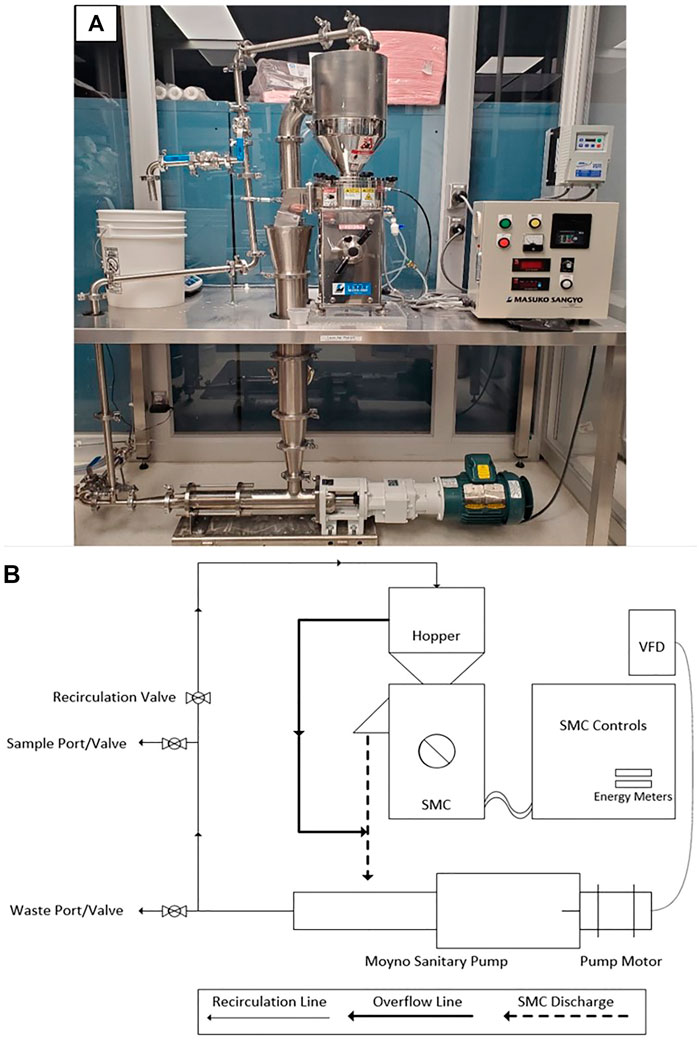
FIGURE 1. Supermasscolloider Refining System (A) SMC refining system and (B) schematic view.
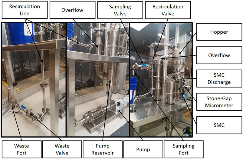
FIGURE 2. Supermasscolloider refining system components.
The SMC system was constructed within a temperature-controlled ISO 7 class cleanroom which included four HEPA filters and a custom recirculation chamber (NCI, Series 591) in order to provide a consistent and clean environment for CNF production. The cleanroom was divided into a gowning area and a working area, with designated zones for each stage of the CNF slurry and CNF sheet production processes. All procedures used in CNF slurry and sheet production were developed, implemented and documented employing Good Manufacturing/Laboratory Practices (World Health Organization 2010).
SMC operation was initiated by opening the gap between the refining stones (via the clearance adjustment) prior to turning on the drive motor; failure to separate the stones prior to engaging the drive motor could result in damaging the stones and/or the motor. The rotational speed of the stones was initially set at 2,000 rpm, and once this was achieved the gap between the stones was gradually decreased until there was a tonal change in the system characteristic of grazing stone contact. The inter-stone distance was set to zero under this condition by locking the gauging sleeve, and was used thereafter as a reference point, termed the zero point. Once the zero point had been determined and set, the inter-stone gap was opened to positive 50 µm in preparation for introduction of the pulp suspension to the system via the feed hopper. Feeding the system with an open but restricted gap ensured that all of the pulp that passed into the system experienced a preliminary refining period and that all fiber aggregates were subsequently broken down to dimensions less than the 50 µm inter-stone gap. When sufficient pulp suspension had been fed to the system to fill the intake line of the pump (14 L), circulation of the suspension was commenced via energizing the pump (set to 14.4 L/min). The system was filled to its 14 L capacity, at which point the slurry in the hopper continuously passed into the overflow passage for recirculation. Once the system was full and recirculation had commenced, a slurry sample, referred to as a zero-time sample, was taken from the recirculation line entering the hopper, via filling a 100 ml container; the inter-stone gap was subsequently reduced to negative 100 µm. There is intentional flexibility in the positioning of the stones such that when they are adjusted to a negative distance setting, the fluid between the stones will keep them flexed outward, preventing harmful contact of the stones whilst providing pressure for grinding.
At each 15-min time interval beyond the zero-time of the run, a 100 ml sample was removed from the system for off-site morphological analysis (with care taken to ensure that the total volume removed for the run did not exceed 1 L). When sampling from the SMC system, the gap was opened for 1 minute to positive 100 µm to allow the slurry to circulate freely throughout the system and to mix with the contents of the pump reservoir. The gap was subsequently returned to negative 100 µm, the cumulative electrical energy consumption of the run was recorded from the power meter, and the 100 ml sample was taken for off-site morphological analysis. It is noted that the SMC was typically run to a targeted cumulative energy consumption value, which was demonstrated to correlate with reproducible CNF fiber morphology. A final sample was collected before removing the CNF from the system by opening of the waste valve on the recirculation line to allow the pump to force the slurry out of the system versus into the hopper. The pump was shut off prior to its inlet line being emptied, thereby mitigating damage to the pump. The system was subsequently cleaned by running a copious amount of DI water through it; the system was deemed clean when no fibers were visible in the waste stream.
CNF slurry was typically refined at 2 wt% solids to a fines content of 90%; the neat slurry was used unmodified to create CNF sheets by spreading onto stainless steel plates. A casting knife film applicator was used to spread CNF into a wet sheet of 75 thousandths of an inch (∼1.9 mm) thickness. The sheets were left to dry overnight on the stainless steel plates under ambient conditions. The dried sheets were removed using razor blades to gently trim the sheets’ edge from the plate followed by lifting the sheets from the top to the bottom as the edges were trimmed. After sheet removal, the sheets were left to adjust to standard temperature and humidity (23°C and 50%RH) in the University of Maine Process Development Center (PDC’s) TAPPI room.
The tensile strength of CNF sheets was measured employing a combination of TAPPI standard methods 220 (pulp handsheets) and 494 (paper and paperboard). Specifically, the sample size was as defined in TAPPI standard method 220 (10 cm in length by 1.5 cm in width), and the rate of elongation remained constant as per TAPPI standard method 494 (25 mm/min). CNF sheets were acclimatized to the temperature and relative humidity of the TAPPI room for 24 h prior to measurements being made. An Instron model 5,564 running the Instron Bluehill software package was employed to perform tensile strength measurements. Samples were cut to the specified dimensions and clamped within the upper and lower grips of the Instron machine, the system was subsequently activated and the extension and load were recorded until the sample broke. It is noted that when casting the CNF sheets, the action of the draw knife spreading the slurry potentially creates a “machine direction”; as such, samples for tensile testing were cut both parallel to and perpendicular to the machine direction. To calculate the Young’s modulus of each sample, load and extension were converted to stress and strain, respectively. Stress was found through dividing load by the cross-sectional area of the test strip. Strain was calculated as the ratio of the deformed length to the original length of the test strip. Stress was plotted on the y-axis as a function of strain on the x-axis. Young’s modulus is defined as the initial, linear, slope of the stress-strain curve and was determined by maximization of the R-squared value of the fitted trend line for each sample (University of Cambridge 2002).
Air permeability of CNF sheets was measured employing a Gurley 4340N Automatic Densometer and Smoothness Tester equipped with an air filter and desiccator to ensure the input air was clean and had a low moisture content. The Densometer was housed in the TAPPI room of the Process Development Center; all CNF sheets were acclimated in the TAPPI room for 24 h prior to measurements being made. The Densometer measured the amount of time required to pass 100 cm3 of air through the material being tested, with data reported in Gurley Seconds. The greater the number of Gurley Seconds measured for a given sample, the less permeable it was. The measurement was performed by placing a CNF sheet into the Densometer where it was clamped in place over a charged cylinder that released air onto one surface of the sheet. Air that passed through the sheet flowed through an exit chamber equipped with a flow meter. The results from each test were recorded manually from the instruments display.
The porosity of CNF sheets was determined via the technique of mercury porosimetry employing a Micromeritics Autopore IV porosimeter and CNF sheets conditioned as described above. Specifically, the mass of a sample of a CNF sheet of approximately 0.02–0.03 g was measured to four decimal places and the sample was mounted in the penetrometer. The penetrometer was subsequently sealed and inserted into the pressure chamber of the porosimeter. The pressure exerted on a reservoir of mercury in contact with the sample was progressively increased, thereby altering the characteristic contact angle of the mercury and forcing it into progressively smaller pores within the sample. The inverse relationship between pore size and applied pressure enabled calculation of pore size, pore size distributions, cumulative volume etc. The resulting data were exported in both numerical and graphical form.
The topography of CNF sheets was measured employing a Tencor Alphastep 500 mechanical profilometer and CNF sheets conditioned as described above. Specifically, CNF sheets were cut into strips approximately 38 mm long by 6 mm wide. Samples were cut in both the machine and cross-machine directions to check for variability. Each sample strip was fixed to a glass slide using double-sided tape. Samples were attached with either the side that dried in contact with the stainless steel plate during sheet formation facing up, or the side that dried exposed to air facing up. Individual samples were loaded into the profilometer such that the stylus could scan from left to right, parallel to the length of the sample and centered on the width of the sample. The stylus position was set to zero at approximately ¼ of the sample length from the left edge. The profilometer was set to scan a 2 mm length and record the average surface roughness. The measurement was repeated for a total of three measurements per sample. It is noted that samples were taken from sheets cast on two different plates. Each combination of plate used for casting, machine or non-machine direction, and exposed surface during drying were tested 6 times.
The MorFi Fiber and Shiv Analyzer (Techpap MorFi Compact) is the standard device employed in the pulp and paper industry to measure fiber size, fiber diameter, distribution of these values, kink angle, etc., The MorFi Fiber and Shiv Analyzer, referred to hereafter as the MorFi, was housed in the Pilot Plant of the UMaine Process Development Center and was employed throughout the present work for CNF fiber analysis. Specifically, a 25 g sample of CNF slurry produced by the supermasscolloider was diluted via addition of DI water to a 1 L volume, followed by a subsequent 1:100 dilution with deionized water to produce a 50 mg/L CNF slurry. The diluted suspension was circulated through the MorFi and several images of the fibers were taken. The MorFi performed multiple calculations on the images of the fibers in the diluted suspension and determined arithmetic means, distributions of fiber physical parameters etc. Fibers that were greater than 200 µm in length were measured by the MorFi; fibers of smaller dimensions that were not able to be measured are termed “fines” and were reported as such. Consequently, a CNF slurry that had been measured by the MorFi as containing 90% fines comprised fibers, 90% of which had lengths less than 200 µm.
MorFi analysis was employed to track the progress of the refining of cellulose pulp to cellulose nanofiber via analysis of slurry samples withdrawn from the SMC at periodic intervals, Figure 3. It is important to note that the feedstock softwood pulp has a significant native percentage of fines (23%), prior to refinement in the SMC. Development of a consistent method to produce CNF resulted in the adoption of a 90% fines slurry at a solids content of 2 wt%.
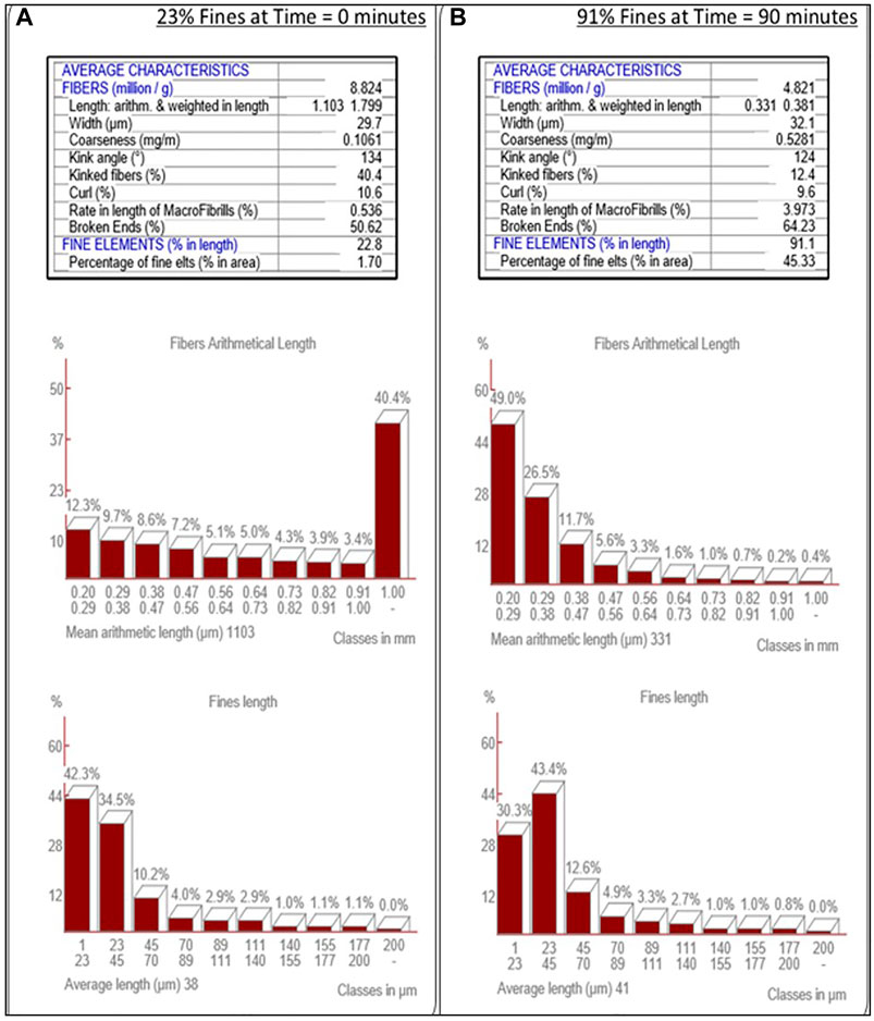
FIGURE 3. MorFi Fiber Characteristic Analysis. MorFi fiber analysis of the transition of fiber into fines through refinement of wood pulp (A) into cellulose nanofibers (B).
Cumulative energy consumption of the drive motor for the rotor of the SMC system (i.e. not including the recirculating pump energy consumption) was shown to be strongly correlated with the resultant cellulose fiber size, and the fiber distribution. As such, desired fiber distribution values were achieved through establishment of a calibration curve via triplicate processing runs and measurement of fiber size/distribution and cumulative energy consumption values. For a sample calibration curve, see Figure 4.
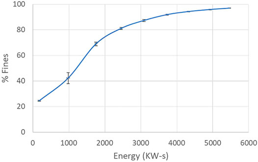
FIGURE 4. Correlation of percent fines with energy consumption. Average of three processing runs with standard deviations for both percent fines and energy consumption displayed.
During the refining process the viscosity of the pulp slurry increases dramatically as the percentage of fines (fibers less than 200 µm) increases, as is evident in Figure 5. The increase in viscosity is attributed to the progressively greater fiber entanglements that occur as the pulp fibers are increasingly segmented and defibrillated. The dramatic increase in viscosity (several orders of magnitude) makes refining a challenge as it becomes increasingly difficult to pump the slurry. Fortunately, however, the CNF slurry is shear thinning, a fact that does enable processing if great care is taken in system design and operation. It is noted that the high viscosity of the CNF slurry also impedes mixing; care must therefore be taken to avoid inconsistencies throughout CNF slurry production, and other downstream processes. The viscosity of a CNF slurry is also heavily dependent upon the solids content. Care must therefore be taken to ensure CNF slurry production is performed at a solids content that enables appropriate fluid flow (typically 3 wt% CNF or less).
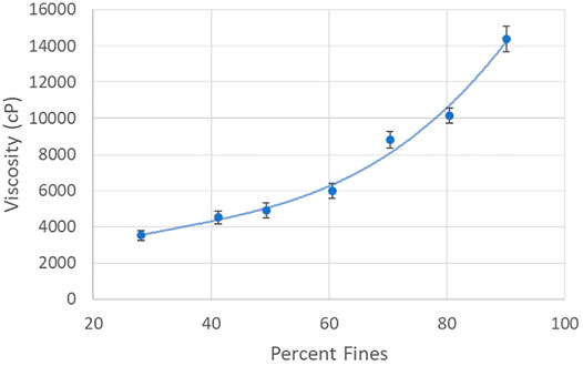
FIGURE 5. Viscosity Characteristics of CNF Production by Percent Fines. Viscosity of refined cellulose nanofiber slurries, at ∼2% solids by weight, over a range of percent fines.
CNF sheets were created by casting 100 ml of 2 wt% CNF slurry directly onto stainless steel plates. It should be noted that in the development phase of CNF sheet production a variety of materials were trialed as casting plates with mixed results. Specifically, plastic and plastic-coated metal plates created deformed and inconsistent sheets, aluminum plates resulted in metal particulate contaminants in the sheet upon removal, and glass plates bound the CNF sheets to the extent that they could not be removed intact. CNF sheets were successfully cast on stainless steel plates and characterized via various techniques as detailed in the following sections.
A series of 12 CNF sheets were created, six each on two different stainless steel plates. The thickness of each sheet was measured in order to assess the consistency of sheet formation. Thickness measurements were made employing a benchtop digital caliper (TMI 49–85). The 12 sheets were measured to have an average thickness of 56.2 µm with a standard deviation of less than 1.5 µm (less than 3% of the sheet thickness), see Table 1. It should be noted that sheet thickness was found to be readily adjustable through variation of the solids content of the CNF slurry employed to cast the sheet, as well as the thickness of the spread slurry.
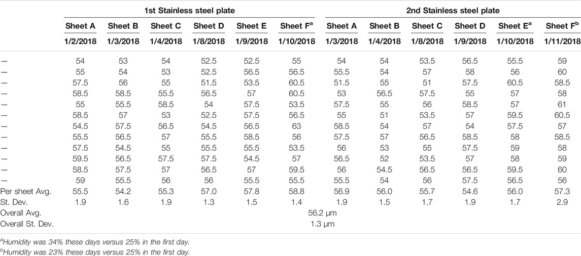
TABLE 1. Sheet Thickness Analysis. Sheet thickness consistency of 12 CNF sheets cast on two separate stainless steel plates, all values reported in µm.
Tensile strength testing was performed on the CNF sheets in order to ascertain the Young’s modulus, or the modulus of elasticity under tension—defined as the ratio of the stress acting on a material to the strain produced. Tensile testing was performed and the Young’s modulus was taken as the gradient of the linear portion of each stress vs. strain curve, as may be seen in Figure 6. Tensile data were recorded for CNF sheets oriented parallel to the machine (blade) direction, with Young’s modulus values observed to range from 4.99 to 5.71 GPa. Tensile data recorded for CNF sheets oriented perpendicular to the machine direction (cross machine direction) resulted in Young’s modulus values in the range of 4.62–5.10 GPa. Statistical analysis via Minitab (two sample t-test with p < 0.001) revealed that the average Young’s modulus of samples taken in the parallel direction was statistically greater than the average of samples taken in the perpendicular direction.
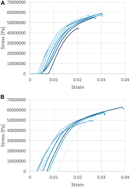
FIGURE 6. Tensile strength testing of CNF sheets. Samples taken in the machine (A) and cross-machine directions (B).
Due to the casting method employed to create the CNF sheets, the resultant sheets possessed two markedly different surfaces. Specifically, the face that dried in contact with the stainless steel plate was smoother and had a greater sheen relative to that which dried exposed to air, as evidenced by both visual and tactile investigation. To quantify the surface roughness of the sheets, sample strips were collected from sheets cast on two different stainless steel plates (designated P1 and P2). Strips were cut in both the machine (blade) and cross-machine direction, (designated M and C, respectively). The surface roughness of all strips was measured employing a Tencor Alphastep 500 mechanical profilometer. The surface roughness of both sides of each sheet was tested with the side that was dried in contact with the steel plate designated S, and the side that was dried exposed to air designated A. For each combination of parameters, two individual CNF strips were cut and analyzed (a and b); each individual measurement was performed in triplicate. Figure 7 presents the surface roughness data obtained. It is evident from examination of Figure 7 that neither the direction that the CNF strip was cut relative to the casting process, nor the individual stainless steel plate employed for casting, had any significant effect on the surface roughness of the sheets. However, the air-exposed and stainless steel plate contacting surfaces were consistently statistically different (2 sample t-test with p < 0.001). Indeed, the surface dried exposed to air had an average surface roughness across all sheets of 3.17 µm, while the surface dried in contact with the stainless steel plate had an average surface roughness across all sheets of 0.70 µm.
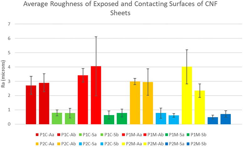
FIGURE 7. Surface Roughness Measurement Results. Average surface roughness (Ra) of two distinct sheet sides. P1-plate 1, P2-plate 2, C-cross machine direction, M-machine direction, A-air exposed, S-steel contacting, a-sample one, and b-sample two.
CNF sheets inherently possess a degree of transparency, a significant attribute in many biomedical applications. In order to ascertain the extent to which CNF sheet transparency could be controlled, sheets of varying thickness were created via modification of the solids content of the slurry cast on the stainless steel plates, and by variation of the height of the casting knife applicator. The resulting dried sheets were conditioned in a temperature and humidity-controlled environment in compliance with TAPPI standards prior to measurement of their thicknesses. All sheets were made in duplicate. One of each duplicate CNF sheet was hot calendared in the UMaine Process Development Center via two passes through the nip of two heated steel rollers. Figure 8 presents the solids content of the slurry employed, the thickness of the sheets resulting from variation of the height of the casting knife applicator, and images depicting the transparency of the calendared and non-calendared sheets. Investigation of Figure 8 reveals that the thinner the initial CNF sheet the greater the transparency, and that the transparency is significantly increased via calendaring.
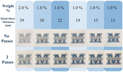
FIGURE 8. CNF Sheet Transparency. The effect of varying sheet thickness and calendaring on transparency.
The air permeability of CNF sheets was determined employing a Gurley 4340N Automatic Densometer and Smoothness Tester. The densometer measures the amount of time required to pass 100 cm3 of air through a sample and reports in units of Gurley Seconds over a range of 0–50,000. Testing of CNF sheets consistently resulted in an output of “Too dense to read”, implying that the sheets were highly impermeable to air and required in excess of 50,000 s for the passage of 100 cm3 of air.
The porosity of CNF sheets was determined employing a Mercury porosimeter. A representative plot of cumulative pore volume vs. pore diameter is presented in Figure 9. Investigation of Figure 9 reveals that the CNF sheet possesses no pores with diameters between 0.01 and 10 µm. It is noted that a spurious data point occurs at a pore diameter of ∼10 µm which is attributed to a mechanical switch in pressure made by the operator to increase the pressure in the sample chamber. At extremely small pore diameters, Figure 9 possesses an anomalous peak (in the 0.01–0.03 µm range). Measurements in this pore diameter regime are known to be affected by the surface roughness of the sheet. As evidenced by the profilometer measurements, the surface of the CNF sheet that was dried in contact with air was statistically rougher than the surface that was dried in contact with the stainless steel plate, likely giving rise to the inconsistent Mercury porosimetry data at very low pore diameters. Taken in combination, the Mercury porosimetry and the air permeability data suggest that the CNF sheets do not have any pores that completely traverse the thickness of the sheet, only small surface vacancies resulting from surface roughness.
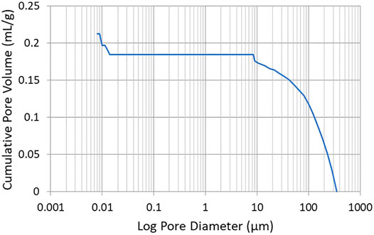
FIGURE 9. Mercury Porosimetery Results. Pore volume analysis of a CNF sheet.
Cellulose nanofiber (CNF) is being increasingly explored as a biodegradable, sustainable, and non-immunogenic material for biomedical applications (Nechyporchuk et al., 2016; Gorgieva and Trček 2019). As such it is critical that a process, or processes, be developed that enable production of CNF in a manner that creates a high quality, reproducible material that may be sterilized in preparation for implantation, or otherwise used in animal/human applications. The present work has developed such a production process for CNF slurry by means of a continuous grinding system. The production equipment was housed within an ISO 7 cleanroom to minimize airborne contamination. The cellulosic feedstock was a commodity softwood bleached kraft pulp, and deionized water was used throughout. The CNF slurry produced by the process was analyzed for fines content employing a MorFi fiber analysis system, and for viscosity via a Brookfield viscometer. The measurements provided confirmation of a consistent fiber/fines content, and a reproducible extent of fiber entanglement, respectively. Since many biomedical applications of CNF require the use of either sheets or other solid forms of the material, the CNF slurry was employed to create CNF films/sheets which were subsequently thoroughly characterized. It was determined that sheet thickness could be reproduced to within approximately 3%, that sheets had a Young’s modulus in the range of 4.6–5.7 GPa, and that the two sides of the sheet formed in the drying process had a statistically different surface roughness (2 sample t-test with p < 0.001). CNF sheets displayed extensive transparency, which could be increased via reduction of the sheet thickness, and via hot calendaring. The sheets were found to be highly impermeable to air, and to have no detectable porosity. CNF sheets produced in the present work were formed into conduits, sterilized via ethylene oxide, and implanted in well over 100 mice, and several non-human primates as peripheral nerve regenerating devices. No evidence of irritation or inflammation were found in any of the CNF implanted animals (data not shown). It is concluded that the CNF slurry production process developed in the present work creates a reproducible material that is well-suited for biomedical applications. Importantly, the process is readily scalable, and may be customized as desired to meet variable product parameters.
The original contributions presented in the study are included in the article, further inquiries can be directed to the corresponding author.
All authors listed have made a substantial, direct, and intellectual contribution to the work and approved it for publication.
This research was funded by a Department of Defense award DoD-A-14–084, an NSF REU Award EEC 1757529 “Explore It! Building the Next Generation of Sustainable Forest Bioproduct Researchers”, the Graduate School of Biomedical Science and Engineering of the University of Maine, and an NIH T32 award #5T32GM132006-02 ‘‘Transdisciplinary Predoctoral Training in Biomedical Science and Engineering.’’
The authors declare that the research was conducted in the absence of any commercial or financial relationships that could be construed as a potential conflict of interest.
All claims expressed in this article are solely those of the authors and do not necessarily represent those of their affiliated organizations, or those of the publisher, the editors and the reviewers. Any product that may be evaluated in this article, or claim that may be made by its manufacturer, is not guaranteed or endorsed by the publisher.
Mercury porosimetry measurements were performed by Lisa Weeks on CNF sheets provided by the authors. Caitlin Howell is gratefully acknowledged for assistance with structuring the documentation of the standard operating procedures for GMP/GLP compliance.
Abol-Fotouh, D., Hassan, M. A., Shokry, H., Roig, A., Azab, M. S., and Kashyout, A. E.-H. B. (2020). Bacterial Nanocellulose from Agro-Industrial Wastes: Low-Cost and Enhanced Production by Komagataeibacter Saccharivorans MD1. Sci. Rep. 10 (1), 1–14. doi:10.1038/s41598-020-60315-9
Ang, S., Haritos, V., and Batchelor, W. (2020). Cellulose Nanofibers from Recycled and Virgin Wood Pulp: A Comparative Study of Fiber Development. Carbohydr. Polym. 234, 115900. doi:10.1016/j.carbpol.2020.115900
Araldi da Silva, B., de Sousa Cunha, R., Valério, A., De Noni Junior, A., Hotza, D., and Gómez González, S. Y. (2021). Electrospinning of Cellulose Using Ionic Liquids: An Overview on Processing and Applications. Eur. Polym. J. 147 (December 2020), 110283. doi:10.1016/j.eurpolymj.2021.110283
de Assis, C. A., Iglesias, M. C., Bilodeau, M., Johnson, D., Phillips, R., Peresin, M. S., et al. (2018). Cellulose Micro- and Nanofibrils (CMNF) Manufacturing - Financial and Risk Assessment. Biofuels, Bioprod. Bioref. 12 (2), 251–264. doi:10.1002/bbb.1835
Gorgieva, Selestina., and Trček, Janja. (2019). Bacterial Cellulose: Production, Modification and Perspectives in Biomedical Applications. Nanomaterials 9 (10), 1352. doi:10.3390/nano9101352
Hsieh, Y.-L. (2018). Cellulose Nanofibers: Electrospinning and Nanocellulose Self-Assemblies, in Advanced Green Composites. 1st Edn, Chap. 2, 67–95. doi:10.1002/9781119323327.ch4
Liu, Q., Lu, Y., Aguedo, M., Jacquet, N., Ouyang, C., He, W., et al. (2017). Isolation of High-Purity Cellulose Nanofibers from Wheat Straw through the Combined Environmentally Friendly Methods of Steam Explosion, Microwave-Assisted Hydrolysis, and Microfluidization. ACS Sustainable Chem. Eng. 5 (7), 6183–6191. doi:10.1021/acssuschemeng.7b01108
Mokhena, T. C., and John, M. J. (2020). Cellulose Nanomaterials: New Generation Materials for Solving Global Issues. Cellulose 27, 1149–1194. doi:10.1007/s10570-019-02889-w
Moon, R. J., Martini, A., Nairn, J., Simonsen, J., and Youngblood, J. (2011). Cellulose Nanomaterials Review: Structure, Properties and Nanocomposites. Chem. Soc. Rev. 40, 3941. doi:10.1039/c0cs00108b
Moon, R. J., Schueneman, G. T., and Simonsen, J. (2016). Overview of Cellulose Nanomaterials, Their Capabilities and Applications. Jom 68 (9), 2383–2394. doi:10.1007/s11837-016-2018-7
Nechyporchuk, O., Belgacem, M. N., and Bras, J. (2016). Production of Cellulose Nanofibrils: A Review of Recent Advances. Ind. Crops Prod. 93, 2–25. doi:10.1016/j.indcrop.2016.02.016
Phanthong, P., Reubroycharoen, P., Hao, X., Xu, G., Abudula, A., and Guan, G. (2018). Nanocellulose: Extraction and Application. Carbon Resour. Convers. 1 (1), 32–43. doi:10.1016/j.crcon.2018.05.004
Piras, C. C., Fernández-Prieto, S., and De Borggraeve, W. M. (2019). Ball Milling: A Green Technology for the Preparation and Functionalisation of Nanocellulose Derivatives. Nanoscale Adv. 1 (3), 937–947. doi:10.1039/c8na00238j
Santos, Ricardo. B., Hart, Peter. W., Jameel, Hasan., and Chang, Hou-Min. (2013). Important Reactions of Lignin. BioResources 8 (1), 1456–1477. doi:10.15376/biores.8.1.1456-1477
Tayeb, A., Amini, E., Ghasemi, S., and Tajvidi, M. (2018). Cellulose Nanomaterials-Binding Properties and Applications: A Review. Molecules 23 (10), 2684. doi:10.3390/molecules23102684
Tibolla, H., Pelissari, F. M., Martins, J. T., Vicente, A. A., and Menegalli, F. C. (2018). Cellulose Nanofibers Produced from Banana Peel by Chemical and Mechanical Treatments: Characterization and Cytotoxicity Assessment. Food Hydrocolloids 75, 192–201. doi:10.1016/j.foodhyd.2017.08.027
Trache, D., TarchounTarchoun, A. F., Derradji, M., Hamidon, T. S., Masruchin, N., Brosse, N., et al. (2020). Nanocellulose: From Fundamentals to Advanced Applications. Front. Chem. 8. doi:10.3389/fchem.2020.00392
University of Cambridge (2002). Property Information - Young’s Modulus and Specific Stiffness. Cambridge, England: Department of Engineering. Available at: http://www-materials.eng.cam.ac.uk/mpsite/properties/non-IE/stiffness.html.
Wang, Q. Q., Zhu, J. Y., Gleisner, R., Kuster, T. A., Baxa, U., and McNeil, S. E. (2012). Morphological Development of Cellulose Fibrils of a Bleached Eucalyptus Pulp by Mechanical Fibrillation. Cellulose 19 (5), 1631–1643. doi:10.1007/s10570-012-9745-x
Wang, W., Mozuch, M. D., Sabo, R. C., Kersten, P., Zhu, J. Y., and Jin, Y. (2015). Production of Cellulose Nanofibrils from Bleached Eucalyptus Fibers by Hyperthermostable Endoglucanase Treatment and Subsequent Microfluidization. Cellulose 22 (1), 351–361. doi:10.1007/s10570-014-0465-2
Wiedenhoeft, Alex. C., and Miller, Regis. B. (2005). “Structure and Function of Wood,” in Handbook of Wood Chemistry and Wood Composites (Danvers, MA: CRC Press), 9–33.
World Health Organization (20102010). WHO Good Practices for Pharmaceutical Quality Control Laboratories. Geneva: WHO Technical Report Series.
Keywords: supermasscolloider, continuous refining, cellulose nanofiber, cellulose defibrillation, cellulose nanofiber slurry, cellulose nanofiber sheet
Citation: Carter N, Grant I, Dewey M, Bourque M and Neivandt DJ (2021) Production and Characterization of Cellulose Nanofiber Slurries and Sheets for Biomedical Applications. Front. Nanotechnol. 3:729743. doi: 10.3389/fnano.2021.729743
Received: 23 June 2021; Accepted: 01 November 2021;
Published: 06 December 2021.
Edited by:
Yogendra Kumar Mishra, University of Southern Denmark, DenmarkCopyright © 2021 Carter, Grant, Dewey, Bourque and Neivandt. This is an open-access article distributed under the terms of the Creative Commons Attribution License (CC BY). The use, distribution or reproduction in other forums is permitted, provided the original author(s) and the copyright owner(s) are credited and that the original publication in this journal is cited, in accordance with accepted academic practice. No use, distribution or reproduction is permitted which does not comply with these terms.
*Correspondence: David J. Neivandt, ZGF2aWQubmVpdmFuZHRAbWFpbmUuZWR1
Disclaimer: All claims expressed in this article are solely those of the authors and do not necessarily represent those of their affiliated organizations, or those of the publisher, the editors and the reviewers. Any product that may be evaluated in this article or claim that may be made by its manufacturer is not guaranteed or endorsed by the publisher.
Research integrity at Frontiers
Learn more about the work of our research integrity team to safeguard the quality of each article we publish.