
94% of researchers rate our articles as excellent or good
Learn more about the work of our research integrity team to safeguard the quality of each article we publish.
Find out more
ORIGINAL RESEARCH article
Front. Nanotechnol., 31 March 2021
Sec. Nanodevices
Volume 3 - 2021 | https://doi.org/10.3389/fnano.2021.660563
This article is part of the Research TopicMemristive Neuromorphics: Materials, Devices, Circuits, Architectures, Algorithms and their Co-DesignView all 13 articles
 Hiroshi Sato1,2
 Hisashi Shima2*
 Toshiki Nokami3
 Toshiyuki Itoh3
 Yusei Honma2
 Yasuhisa Naitoh2
 Hiroyuki Akinaga2
 Kentaro Kinoshita1
We demonstrate a new memristive device (IL-Memristor), in which an ionic liquid (IL) serve as a material to control the volatility of the resistance. ILs are ultra-low vapor pressure liquids consisting of cations and anions at room temperature, and their introduction into solid-state processes can provide new avenues in electronic device fabrication. Because the device resistance change in IL-Memristor is governed by a Cu filament formation/rupture in IL, we considered that the Cu filament stability affects the data retention characteristics. Therefore, we controlled the data retention time by clarifying the corrosion mechanism and performing the IL material design based on the results. It was found out that the corrosion of Cu filaments in the IL was ruled by the comproportionation reaction, and that the data retention characteristics of the devices varied depending on the valence of Cu ions added to the IL. Actually, IL-Memristors involving Cu(II) and Cu(I) show volatile and non-volatile nature with respect to the programmed resistance value, respectively. Our results showed that data volatility can be controlled through the metal ion species added to the IL. The present work indicates that IL-memristor is suitable for unique applications such as artificial neuron with tunable fading characteristics that is applicable to phenomena with a wide range of timescale.
Memristors, which were proposed as the fourth fundamental elements of electric circuitry in 1971 (Chua, 1971), have been extensively investigated in memory and neuromorphic devices since the reports of the TiO2 memristor in 2008 (Strukov et al., 2008; Yang et al., 2008). A memristor is a two-terminal passive device whose resistance changes with the amount of charge passing through it and is expected to advance electronics and electrochemical research (Sun B. et al., 2019). As the mechanism of resistance change in the memristor, not only the movement of oxygen vacancies (Sawa, 2008; Akinaga and Shima, 2010) but also the electrochemical metallization has been proposed (Gan et al., 2019). Here we propose an IL-Memristor in which ionic liquids (ILs) are introduced in a solid device as a new memristive material. ILs are ultra-low vapor pressure liquids comprised cations and anions at room temperature (Wasserscheid and Welton, 2002; Hallett and Welton, 2011) and can be used as chemical reaction field because of their wide potential window (Arimoto et al., 2008), making them suitable candidates for electronic devices (Harada et al., 2015a,b, 2016; Saito and Iwasa, 2015; Kinoshita et al., 2017; Yamaoka et al., 2017). Because ILs are stable in vacuum, they can be incorporated into existing microfabrication processes. The stability of the metal in the IL impacts the data retention characteristics in electrochemical metallization type memristors. Expanding the range of device applications is possible by controlling the metal filament stability in IL-Memristor. The stable metal filament have been applied to a non-volatile memory, such as conducting-bridge RAM, which are expected to become next-generation memory devices because of their simple structure and low power consumption (Waser et al., 2009, 2016; Valov et al., 2011). Besides, the stable filament has been used to demonstrate electronics synapse devices, in which a long-term potentiation (LTP) and long-term depression (LTD) as well as spike-timing-dependent plasticity (STDP) in the biological synapse are successfully emulated (Jeong et al., 2016; Shi et al., 2018). Recently, the unstable filament also attracts considerable attention because the resultant temporal resistance change is applicable to the emerging devices for the human brain inspired computing (Hasegawa et al., 2011; Deng et al., 2015; Ascoli et al., 2016; Zhang et al., 2018; Midya et al., 2019; Wang et al., 2019; Zhu et al., 2020).
As an influencing factor on the Cu filament stability, we focused on the comproportionation reaction of Cu in IL reported by Murase et al. (2001). We directly detected the formation of Cu(I) from Cu(II) in IL dropped on a thin Cu film using X-ray photoelectron spectroscopy (XPS) by taking advantage of ultra-low vapor pressure of ILs in the vacuum. We used this reaction to control the data retention characteristics of the IL-Memristor. As expected from the XPS measurement results, the data retention time was more than 10 times longer in Cu(I)-doped IL-Memristor than that in Cu(II)-doped IL-Memristor although reproducible resistance change was observed in both devices. These results indicate that IL-Memristor with controllable data volatility can be produced through changing metal ion species in ILs.
Figure 1A shows the SEM image of IL-Memristor. Figure 1B shows the cross-sectional view of IL-Memristor for lines A-B in Figure 1A. A Ta (1 nm)/Pt (20 nm)/Ta (1 nm) film was deposited on a SiO2 substrate by sputtering, followed by chemical vapor deposition of SiO2 (30 nm). Here, the Ta layer acts as the adhesion layer between the SiO2 and Pt layers, and the Pt layer acts as the inert electrode (IE). A pore structure with an area of 1 × 1 μm, which determined the device size, was microfabricated in the SiO2 layer by conventional photolithography and dry etching. As shown in Figures 1C,D, we used a W needle attached to a precision positioner to supply the IL microdroplet on the microfabricated IE and pore structure. The Cu active electrode (AE) patterns were prepared with the mask-through sputtering process using a metal mask. The thickness of Cu AE is 50 nm. The stacking structure of the present device is represented as Cu (50 nm)/IL (30 nm)/Pt (20 nm). We confirmed that the pore was successfully filled with IL from the results of the electrical measurement, which is explained in more detail in the Supplementary Material. 1-Butyl-3-methylimidazolium bis(trifluoromethyl sulfonyl)amide ([bmim][Tf2N]) was used as the IL (Harada et al., 2015a). Cu(I) was introduced into this IL by electrolysis (Abedin et al., 2007; Qiu et al., 2010). The introduction of Cu(II) was conducted by dissolving Cu(Tf2N)2 metal salts. Hereafter, Cu(I)-doped IL and Cu(II)-doped IL are denoted as Cu(I)-IL and Cu(II)-IL, respectively. In addition to that, the device using Cu(I)-IL and Cu(II)-IL are represented as Cu(I)-IL-Memristor and Cu(II)-IL-Memristor, respectively.
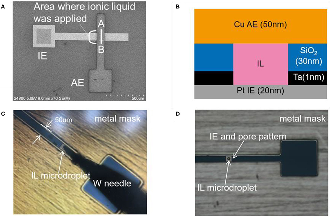
Figure 1. (A) The SEM image of IL-Memristor and (B) the cross-sectional view of IL-Memristor for lines A-B in (A). Photographs of (C) the W needle used to deliver IL microdroplet and (D) IL microdroplet on the IE and pore pattern. A metal mask for Cu AE pattering is also shown in (C,D). IL is filled in a pore structure microfabricated in the 30 nm thick SiO2 layer between Cu and Pt electrodes. In IL-Memristor, IL is used as a location for the Cu ion transport.
Optical microscopy of the Cu pattern in the IL was performed in the atmosphere at room temperature. In XPS measurements, ULVAC-PHI Quantera II applying a monochromatic Al Kα X-ray source (1486.6 eV) was used. The photoelectron take-off angle in XPS was 45°. Cu patterns deposited on SiO2 substrates were introduced into the IL and observed by an optical microscope. After 1 h, the IL was sequentially washed away by acetone and ethanol, and the Cu pattern height was measured using a surface profiler. We measured current–voltage (I–V), data retention, and fading characteristics using a semiconductor parameter analyzer (Agilent B1500A). For the data retention characteristics, the reading voltage (−20 mV) was continuously applied during the measurement, and the current readings were taken at regular intervals.
Shown in Figure 2A is the schematic illustration for the sample configuration to observe the Cu pattern dissolution process in IL. In this experiment, an IL droplet was dropped on the Cu patterns by using a micropipette. The corresponding photograph of the IL droplet and Cu patterns are depicted in Figure 2B. Figures 2C–E show the optical microscope images of the Cu pattern on SiO2 immediately after, 15 min after, and 60 min after Cu(I)-IL dropping, respectively. Figures 2F–H show the optical microscope images of the Cu pattern on SiO2 collected immediately after, 15 min after, and 60 min after Cu(II)-IL dropping, respectively. No change was observed in the shape of the Cu pattern in the case of Cu(I)-IL, whereas the Cu pattern was dissolved from the outside after 15 min in the case of Cu(II)-IL. Finally, the Cu pattern in Cu(II)-IL disappeared after 60 min. Although such electronics materials dissolution was an undesired negative phenomenon in terms of the device reliability and long-term use in the conventional electronics, its active utilization is proposed in the emerging field called transient electronics (Cheng and Vepachedu, 2016; Fu et al., 2016). The dissolution of Cu was also confirmed from the variation in the Cu pattern height measured by the surface profiler. Figures 3A,B show the surface profiler measurement results for the Cu pattern in Cu(I)- and Cu(II)-IL, respectively. The red and blue horizontal lines in Figures 2E,H correspond to the scanned location by the surface profiler shown in Figures 3A,B, respectively. When Cu(I)-IL was supplied, the Cu height pattern was almost the same as that of the as-prepared state, even after 60 min. This result indicates that the Cu pattern was not corroded in Cu(I)-IL. Moreover, when Cu(II)-IL was supplied, the Cu pattern height decreased over time and became <10 nm after 60 min, indicating that the Cu pattern was dissolved in Cu(II)-IL. As reported by Murase et al. (2001), Cu dissolution in Cu(II)-IL occurs because of the comproportionation reaction. To confirm this reaction, the chemical states of Cu in Cu(II)-IL on the Cu thin film were analyzed via XPS.
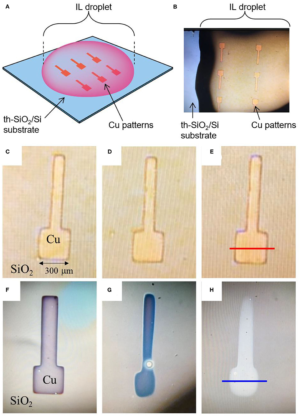
Figure 2. (A) Schematic illustration and (B) photograph of Cu patterns immersed in the IL droplet. Magnified image of Cu thin film patterns (C,F) immediately after, (D,G) 15 min after, (E,H) 60 min after they were introduced into Cu(I)-IL and Cu(II)-IL, respectively. The thickness of Cu pattern is 50 nm. When Cu pattern is in Cu(I)-IL, the appearance of Cu pattern exhibited almost no change with time. On the other hands, Cu pattern gradually disappeared in Cu(II)-IL. The red and blue horizontal lines in (E,H) correspond to the scan position for the surface profiles in Figures 3A,B.
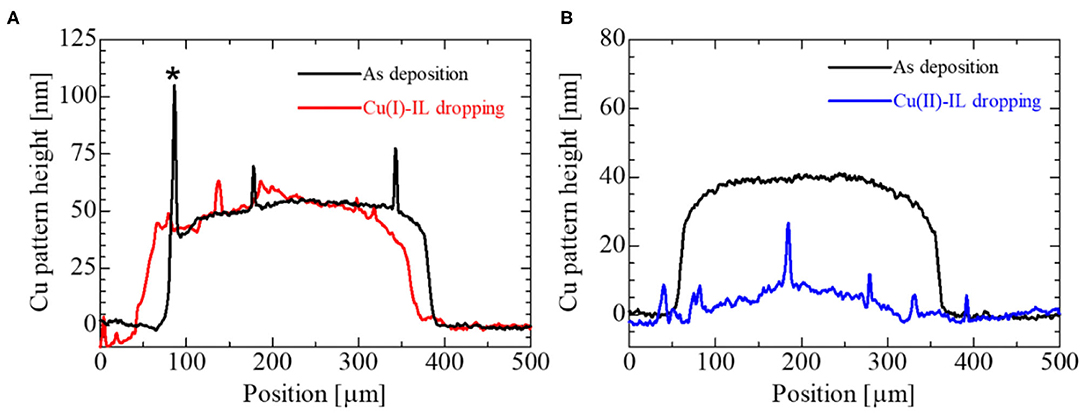
Figure 3. The surface profiler results for (A) Cu(I)-IL and (B) Cu(II)-IL dropped onto the Cu pattern. The red curve in (A) is the surface profile measured along the red horizontal line in Figure 2E. The blue curve in (B) correspond to the surface profile along the blue horizontal line in Figure 2H. The black lines are the surface profiles before the Cu patterns are immersed in the IL. Note that the spiky peak shape at the edge of the Cu pattern plotted by the black line in (A) marked with an asterisk (*) is thought to be a side-wall fence structure formed during the mask-through sputtering process. The profiles for the Cu patterns dipped in IL were measured after removing IL by acetone and ethanol.
Because the ionization of the Cu metal [Cu(0)] is the possible origin for Cu dissolution, we conducted XPS measurement on IL/Cu (Figure 4A) and IL/SiO2 (Figure 4B) to identify the change in Cu valence state during the dissolution. The former was prepared by dropping IL onto the Cu-sputtered SiO2/Si substrate. The thickness of the Cu thin film was 50 nm. The latter was prepared as the control in which IL was dropped directly on the SiO2/Si substrate. The area of the IL droplet in each case was ~5 mm in diameter, which is much larger than the detection area of the XPS measurement (100 μm in diameter). In addition, the IL droplet on the substrate is thick enough to be visible for the human eye (roughly several 100 μm) and it is much thicker than the detection depth of the present XPS measurement (<10 nm). Therefore, from the viewpoint of the size and thickness of the IL droplet, the Cu signal comes only from IL. In the present study, XPS measurements were started 1 h after dropping IL to ensure adequate time for Cu dissolution.

Figure 4. Schematic illustrations of (A) IL/Cu and (B) IL/SiO2 used for XPS measurements. The size of the substrate and IL drop (roughly 5 mm in diameter) is much larger than the detection area of the XPS instrument (100 μm in diameter).
Figure 5A shows the Cu 2p3/2 spectra for IL/Cu and IL/SiO2. Because Cu(Tf2N)2 dissolved in [bmim][Tf2N], the XPS signal of Cu species was detected even in IL/SiO2. The signal intensity of the Cu 2p3/2 spectrum for IL/Cu is much larger than that for IL/SiO2, which can be attributed to the increase in Cu content in IL as a result of the Cu dissolution. The chemical bonding state of Cu in IL/Cu can be estimated from the main peak position of the Cu 2p3/2 spectrum. The peak positions of the Cu 2p3/2 spectra in both IL/Cu and IL/SiO2 are close to those in Cu(NO3)2 (935.51 eV) and CuSO4 (936.00 eV) (Moretti and Beck, 2019). According to the previous reports, electrons delocalize within the S–N–S structure in Tf2N anion (Forsyth et al., 2002; Hapiot and Lagrost, 2008; Smith et al., 2018). Additionally, because oxygen is more electronegative than nitrogen and sulfur, it is expected that the electrons of Cu in the IL are shared by S, N, and O in Tf2N anion. Thus, the larger intensity of the Cu 2p3/2 spectrum for IL/Cu proves that the number of Cu cations interacting with Tf2N anions increased during the Cu dissolution in the IL. As shown in Figures 5B,C, the waveform analysis for the Cu 2p3/2 XPS spectra was conducted in order to investigate the Cu valence state in the IL in more detail. Here, the main peak was labeled as Peak 1, and the satellite structure was split into two peaks labeled as Peak 2 and Peak 3. The peak position for Peak 1 in IL/Cu was 935.75 eV, whereas that in IL/SiO2 was 936 eV. The lower binding energy value for Peak 1 in IL/Cu implied that not only Cu(II) but also Cu(I) was present in the IL on the Cu thin film. Although the constituent metal element is identical in the ionic material, the core-level binding energy becomes higher when the valence of the metal element (cation) increases because an increasing number of valence electrons is attracted by the neighboring anions. For instance, in the case of the Cu–O binary system (Cu2O and CuO), the main peak position shifts to a higher binding energy when the valence of Cu is increased from Cu(I) in Cu2O to Cu(II) in CuO (Moretti and Beck, 2019). By contrast, Peak 1 shifted to a lower binding energy in IL/Cu compared to that in IL/SiO2, which can be related to the valence state decrease in Cu [i.e., the formation of Cu(I)]. Regarding the satellite structure in the Cu 2p3/2 spectra, a strong satellite structure was observed in both samples, indicating that Cu(II) was involved in the IL. This is reasonable because Cu(Tf2N)2 dissolved in [bmim][Tf2N] has the divalent ions of Cu(II). However, the characteristics of the satellite structure of IL/Cu differ from that of IL/SiO2. In the case of IL/SiO2, the area ratio of Peak 3 to Peak 2, i.e., Peak 3/Peak 2, was ~0.97, whereas the value of Peak 3/Peak 2 in IL/Cu was ~1.1. The larger Peak 3/Peak 2 value in IL/Cu than that in IL/SiO2 is due to the Cu(I) formation, which may be accompanied by the weak satellite structure in Cu 2p3/2 spectrum, as observed for Cu(I) in Cu2O (Barreca et al., 2007; Wang et al., 2007).
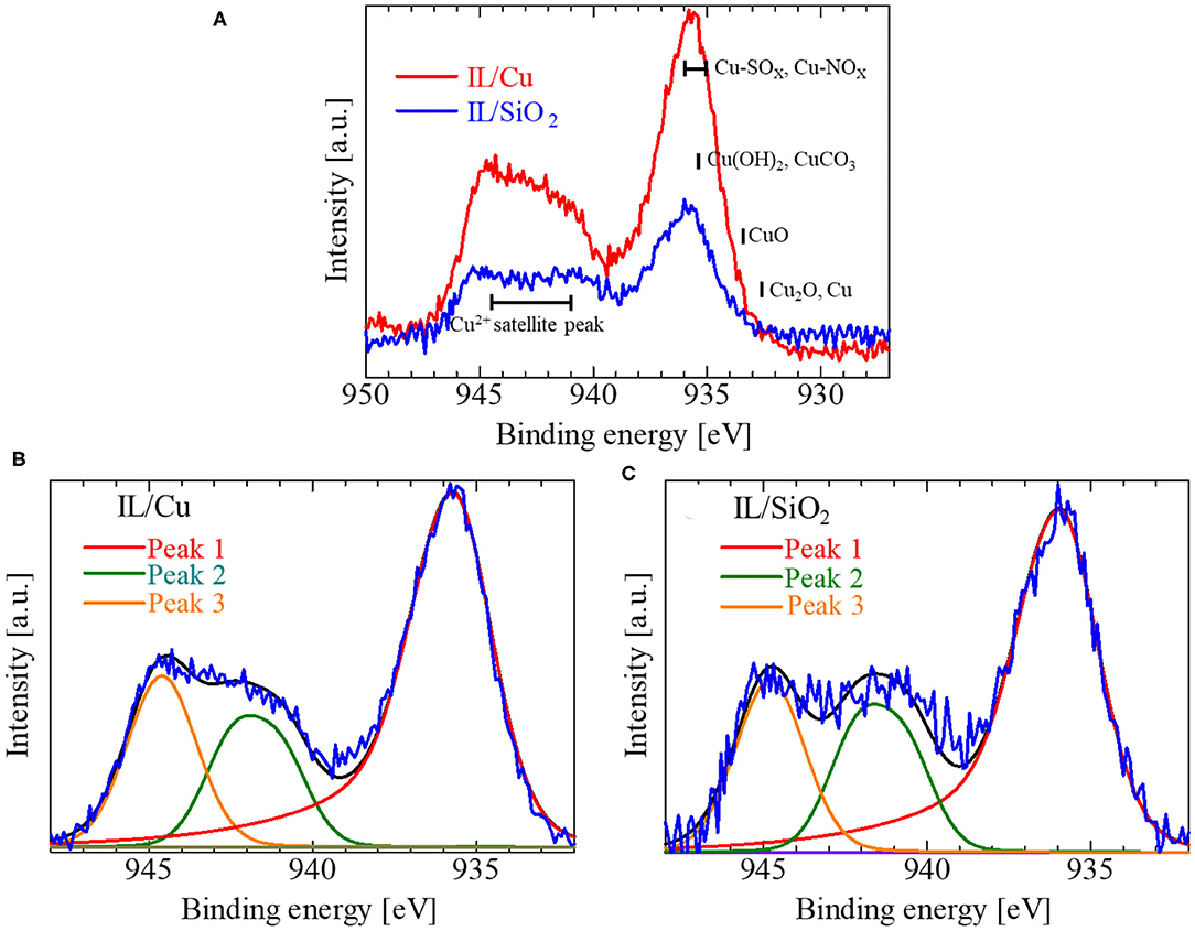
Figure 5. (A) Cu 2p3/2 spectra for IL/Cu and IL/SiO2 and the waveform analysis results for the Cu 2p3/2 spectrum in (B) IL/Cu and (C) IL/SiO2. In (A), the peak positions for some typical Cu compounds as well as Cu(II) satellite peaks are represented by the solid black bars. In (B,C), red, green, and orange curves are the fitting results for the peak separation. Black curves are the summation of those curves.
Considering the above Cu 2p3/2 XPS spectra measurement results, the possible chemical reaction for Cu dissolution is
From the viewpoint of the Cu valence state, Cu dissolution is induced by the following comproportionation reaction:
Two other signs of Cu(I) formation in IL/Cu were obtained. One was the Cu LMM Auger electron spectrum (Figure 6). The intensity of the Cu LMM Auger electron spectrum in IL/Cu is much larger than that in IL/SiO2. A similar change in the Cu LMM Auger spectrum was observed when Cu(I) was introduced in the [MAP][Tf2N] by the electrolysis of Cu (Qiu et al., 2010). Another was the shape of the N 1s XPS spectra in IL/Cu (Figure 7A) and IL/SiO2 (Figure 7B). The N 1s XPS spectrum can be separated into two peaks (Peaks 4 and 6 in Figure 7A) for IL/Cu, whereas it can be separated into three peaks (Peaks 4–6 in Figure 7B) for IL/SiO2. Peaks 4, 5, and 6 correspond to N in bmim cation, N in Tf2N anion having the interaction with metal cations, and N in free Tf2N anion (Caporali et al., 2016). Peak 5 in IL/Cu disappeared in Ag(I) containing [bmim][Tf2N], whereas it was observed in [bmim][Tf2N] with divalent metal cations, such as Cu(II), Ni(II), and Zn(II) (Caporali et al., 2016). As observed in the Cu 2p3/2 spectra, the binding energy between Cu cation and Tf2N anion was weakened because of the formation of Cu(I), which may have caused the disappearance of Peak 5 in Figure 7A. Such feature in N 1s XPS spectrum, i.e., the disappearance of Peak 5, was also observed in Cu(I)-IL prepared by the electrolysis (see Supplementary Material). Regarding Cu(I) in the present IL, there is a possibility that Cu(I) partly forms the carbene complex with imidazolium cation according to the previous studies on the N-heterocyclic carbenes coordinated to metals (Hapiot and Lagrost, 2008; Hopkinson et al., 2014).
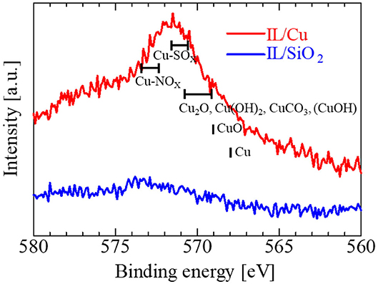
Figure 6. Cu LMM Auger electron spectra for IL/Cu (red) and IL/SiO2 (blue). The peak positions for some typical Cu compounds are depicted by black bars.
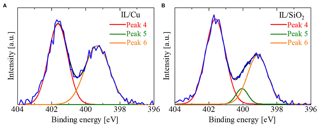
Figure 7. Waveform analysis for N 1s XPS spectrum in (A) IL/Cu and (B) IL/SiO2. Red, green, and orange curves are the fitting results for peak separation and black curves are the summation of those curves. For IL/Cu in (A), the peak intensity for Peak 5 was zero.
The operating mechanism of the IL-Memristor is as follows: when a voltage is applied to the AE, metal ions dissolve in the IL and deposit on the IE to form filaments, resulting in a low resistance state (LRS). Afterward, by applying a negative voltage to the AE in LRS, filaments are ruptured, resulting in a high resistance state (HRS). The switching from HRS to LRS is called SET, whereas that from LRS to HRS is called RESET. Figure 8A shows the I–V characteristics of the Cu(I)-IL-Memristor and Cu(II)-IL-Memristor, which were plotted using the median values calculated from 500 cycles. It should be noted that the number of DC sweep cycle in the present study for evaluating the statistical distribution in the operating voltages is comparable to or larger than those in the previous reports (Yan et al., 2017, 2019a). As indicated by the blue and red arrows in Figure 8A, the voltage values when the filament formation/rupture occurs are represented as VSET/VRESET, respectively. Figure 8B shows the cumulative probabilities of the operating voltage (VSET and VRESET) for the Cu(I)-IL-Memristor and Cu(II)-IL-Memristor. In Figures 8A,B, the blue circles show the Cu(II)-IL-Memristor, and the red triangles show the Cu(I)-IL-Memristor. The VSET of the Cu(I)-IL-Memristor was lower than that of the Cu(II)-IL-Memristor. The comproportionation reaction affects each memristor differently: in the Cu(I)-IL-Memristor, Cu easily deposits on the IE, whereas in the Cu(II)-IL-Memristor, Cu easily dissolves from the AE. The reduction reaction (Cu deposition) on the IE is more dominant in affecting the SET process than the oxidation reaction (Cu dissolution) on the AE because the VSET was lower in the Cu(I)-IL-Memristor than in the Cu(II)-IL-Memristor. This result was consistent with previous reports suggesting that the Helmholtz layer formed on the IE surface and the proton-accepting ability of ILs affect the SET process (Harada et al., 2016; Yamaoka et al., 2017). Additionally, the distribution of VRESET is insusceptible to the Cu valence state in the IL. Assuming that the operating mechanism for the RESET process is mainly based on Joule heating (Tsuruoka et al., 2010; Sun et al., 2014), Cu valence insusceptibility of VRESET may be because it masks the impact of corrosion by the comproportionation reaction. From Figure 8B, it is necessary to point out that the Cu(I)-IL-Memristors still have statistical variabilities in the values of VRESET and VSET. It is considered that such variabilities strongly affect the device reliabilities such as cycle endurance characteristics because it results in the resistance switching failure during the cycle endurance test. Therefore, the suppression of the operating voltage variabilities through the development of materials, device structures, and fabrication processes for IL-Memristor is required. In terms of the device-to-device reproducibility, there is some device-to-device difference in the SET voltage distribution in Figure 8B (see Supplementary Material). However, the impact of the Cu valence on VSET is qualitatively assured. One of the possible reasons for the device-to-device difference is that the volume of the IL microdroplet involved in each IL-Memristor is uncontrollable at present because it is transferred manually by using a W needle. The improvement of the device fabrication process such as adopting the ink-jet technology is required to confirm the device-to-device reproducibility.
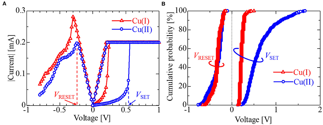
Figure 8. (A) I–V characteristics and (B) cumulative probabilities of Cu(I)-IL-Memristor and Cu(II)-IL-Memristor. Red and blue plots, respectively corresponds to the data obtained from Cu(I)-IL-Memristor and Cu(II)-IL-Memristor. VSET was defined as the voltage value just before the measured current reaches the current compliance value (Icomp). VRESET was defined as the voltage at which the current value in the RESET process is maximized. The red and blue vertical dotted lines in (A) indicated the VRESET and VSET values for the case of Cu(II)-IL-Memristor shown as an example. Under the negative voltage, only the voltage scan from the origin to the negative direction was conducted in order to avoid the excessive voltage stress (For more detail, see Supplementary Material).
Figure 9 depicts the data retention characteristics of IL-Memristors. Data retention characteristics generally depend on the current level. To confirm the data retention characteristics at various current values, Icomp was set at 10, 20, and 200 μA. The Cu(II)-IL-Memristor showed a short data retention time (<103 s), whereas the Cu(I)-IL-Memristor showed a relatively long data retention time (more than 104 s). This indicates that the Cu filament was corroded by the comproportionation reaction in Cu(II)-IL, as expected from optical microscopy and XPS results of the Cu pattern in IL. Importantly, the volatility and non-volatility of the data retention characteristics in IL-Memristor can be controlled by changing metal ion species added to the IL. We found that the Cu(I)-IL-Memristor was more suitable for non-volatile memory applications compared with the Cu(II)-IL-Memristor. As shown in Figure 9, the resistance value of LRS in Cu(I)-IL-Memristor can be increased by decreasing Icomp. Therefore, both the low current operation and good data retention are compatibly realized in Cu(I)-IL-Memristor. Although the minimum value of Icomp in the present study is 10 μA at present, the value of Icomp can be further decreased by decreasing the device area because the device resistance in HRS inversely scales with the device area. This is also favorable because the device size miniaturization is expected to promote the energy-conserving device operation.
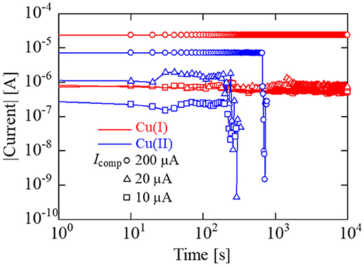
Figure 9. Data retention characteristics of Cu(I)-IL-Memristor (red) and Cu(II)-IL-Memristor (blue). For both devices, Icomp was set at 10, 20, and 200 μA. The Cu(II)-IL-Memristor showed a short data retention time (<103 s), whereas the Cu(I)-IL-Memristor showed a relatively long data retention time (more than 104 s).
As shown in Figure 9, the Cu(II)-IL-Memristor demonstrated data volatility. Recently, such volatile memristors attract considerable attention because of the applicability to the human brain inspired computing. Various materials including solid oxide and sulfides exhibiting voltage resistance change are intensively investigated in order to realize artificial synaptic devices which mimic the information processing function of biological synapse (Hasegawa et al., 2012; Wang et al., 2016; Sun J. et al., 2019; Yan et al., 2019b). In addition, the memristors exhibiting such time-dependent resistance change are developed as the physical reservoir device for the reservoir computing (RC), in which the fading memory function is one of the essential requirements for the device (Tanaka et al., 2019). It has been pointed out that the timescale of the resistance change influences the time period between input signals to the reservoir and the information processing time (Midya et al., 2019). Figure 10A schematically illustrates the measurement method for the fading characteristics of the Cu(II)-IL-Memristor. At first, a SET pulse having a pulse height/width of hSET/wSET was applied to the IL-Memristor in HRS to slightly decrease the device resistance. Immediately after the application of the SET pulse, a read pulse with a height of hREAD was applied, and the current was monitored at regular intervals. For Cu(II)-IL-Memristor, hSET/wSET was +0.6 V/1 ms, while hREAD was −100 mV. Because the pulse voltage was used in this experiment, the SET process was incomplete although the pulse voltage height was larger than the median value of VSET in Figure 8, which was evaluated by DC voltage sweep. Figure 10B shows the results of the fading characteristics of the Cu(II)-IL-Memristor, indicating a gradual current decrease. For comparison, fading characteristics of the Cu(I)-IL-Memristor was also evaluated (Figure 10C). For Cu(I)-IL-Memristor, hSET/wSET was +1.5 V/10 μs, while hREAD was −100 mV. During the reading process, about 45% increase of the resistance (from 15.6 to 22.8 kΩ was observed for 100 ms in Cu(II)-IL-Memristor. On the other hands, about 19% increase of the resistance (from 13.6 to 16.3 kΩ was observed for 800 ms in Cu(I)-IL-Memristor. The faster resistance change in Cu(II)-IL-Memristor suggests that the incomplete filament formation and subsequent dissolution by the comproportionation reaction in Cu(II)-IL lead to the time-dependent resistance change with a timescale of 100 ms. The timescale observed in Cu(II)-IL-Memristor is almost comparable to that observed in a solid diffusive memristor for RC (Midya et al., 2019). Therefore, the present results indicate that the Cu(II)-IL-Memristor is suitable for AI applications such as RC because of their fading memory characteristics. Moreover, the present results also imply that controlling the time-dependent resistance change timescale depending on the task executed in the reservoir is expected by selecting the appropriate IL in IL-Memristor.
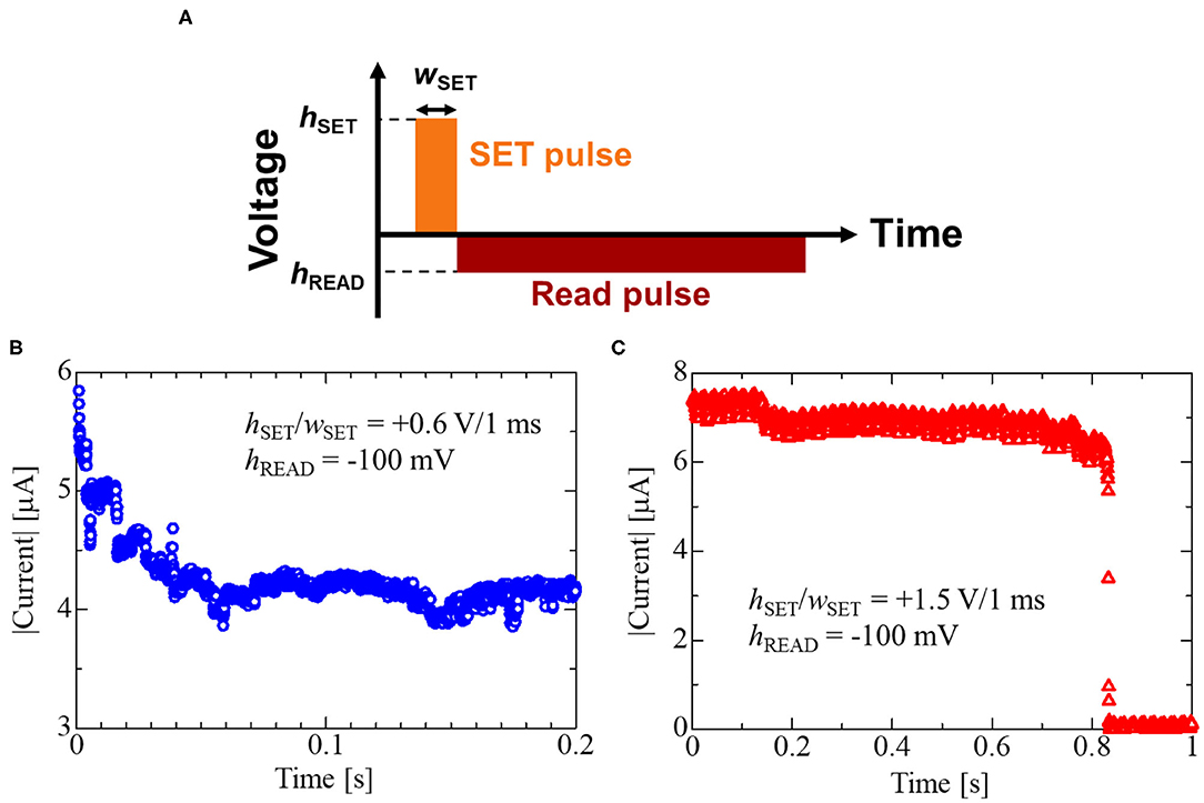
Figure 10. (A) Measurement method for fading characteristics and the results of the fading characteristics of (B) the Cu(II)-IL-Memristor and (C) Cu(I)-IL-Memristor. In (A), hSET and wSET denote the pulse voltage height and width for the SET pulse, while hREAD is the pulse voltage height for the read pulse. The values for hSET, wSET, and hREAD used in the present study are specified in (B,C). The faster fading of the current value was observed in Cu(II)-IL-Memristor compared to Cu(I)-IL-Memristor.
Cu corrosion in ILs was investigated by XPS. Based on this corrosion mechanism, we fabricated two types of devices, Cu(I)-IL-Memristor and Cu(II)-IL-Memristor, and evaluated their data retention characteristics. The Cu(II)-IL-Memristor showed data volatility because the comproportionation reaction promoted the corrosion of Cu filaments, whereas the Cu(I)-IL-Memristor was non-volatile. Our results show that data volatility and non-volatility can be easily controlled by changing metal ion species added to the IL. Additionally, the fading characteristics of the Cu(II)-IL-Memristor, where the current value gradually decreased over 100 ms, were confirmed. The Cu dissolution in IL and relevant time-dependent resistance change observed in IL-Memristor imply the adaptability of ILs and IL-Memristor to the emerging electronic and information processing technologies such as transient electronics and reservoir computing.
The original contributions presented in the study are included in the article/Supplementary Material, further inquiries can be directed to the corresponding author.
HSa, HSh, YN, HA, and KK conceived the experiments. HSh and YH prepared the devices. TN and TI synthesized the ionic liquids. HSa and HSh conducted the observations and measurements. HSa, HSh, HA, and KK analyzed the results. HSa, HSh, and KK wrote the manuscript. All authors contributed to the discussion about the results and commented on the manuscript.
A part of this work was financially supported by NAGASE & CO., LTD. New Value Creation Office.
The authors declare that the research was conducted in the absence of any commercial or financial relationships that could be construed as a potential conflict of interest.
A part of this work was conducted at NIMS Nanofabrication Platform, supported by Nanotechnology Platform Program of the Ministry of Education, Culture, Sports, Science and Technology‘(MEXT), Japan, Grant Number JPMXP09F20NM0072. We thank Enago (www.enago.jp) for the English language review.
The Supplementary Material for this article can be found online at: https://www.frontiersin.org/articles/10.3389/fnano.2021.660563/full#supplementary-material
Abedin, S. Z. E., Saad, A. Y., Farag, H. K., Borisenko, N., Liu, Q. X., and Endres, F. (2007). Electrodeposition of selenium, indium and copper in an air- and water-stable ionic liquid at variable temperatures. Electrochim. Acta 52, 2746–2754. doi: 10.1016/j.electacta.2006.08.064
Akinaga, H., and Shima, H. (2010). Resistive Random Access Memory (ReRAM) based on metal oxides. Proc. IEEE 98, 2237–2251. doi: 10.1109/JPROC.2010.2070830
Arimoto, S., Kageyama, H., Torimoto, T., and Kuwabata, S. (2008). Development of in situ scanning electron microscope system for real time observation of metal deposition from ionic liquid. Electrochem. Commun. 10, 1901–1904. doi: 10.1016/j.elecom.2008.10.003
Ascoli, A., Tetzlaff, R., Chua, L. O., Strachan, J. P., and Williams, R. S. (2016). “Fading memory effects in a memristor for cellular nanoscale network applications,” in 2016 Design, Automation, and Test in Europe Conference and Exhibition (DATE) (Dresden), 421–425.
Barreca, D., Gasparotto, A., and Tondello, E. (2007). CVD Cu2O and CuO nanosystems characterized by XPS. Surf. Sci. Spectra 14, 41–51. doi: 10.1116/11.20080701
Caporali, S., Pedio, M., Chiappe, C., Pomelli, C. S., Acres, R. G., and Bardi, U. (2016). Surface study of metal-containing ionic liquids by means of photoemission and absorption spectroscopies. Surf. Sci. 648, 360–365. doi: 10.1016/j.susc.2015.12.014
Cheng, H., and Vepachedu, V. (2016). Recent development of transient electronics. Theor. Appl. Mech. Lett. 6, 21–31. doi: 10.1016/j.taml.2015.11.012
Chua, L. (1971). Memristor-the missing circuit element. IEEE Trans. Circuit Theory 18, 507–519. doi: 10.1109/TCT.1971.1083337
Deng, L., Li, G., Deng, N., Wang, D., Zhang, Z., He, W., et al. (2015). Complex learning in bio-plausible memristive networks. Sci. Rep. 5:10684. doi: 10.1038/srep10684
Forsyth, C. M., MacFarlane, D. R., Golding, J. J., Huang, J., Sun, J., and Forsyth, M. (2002). Structural characterization of novel ionic materials incorporating the bis(trifluoromethanesulfonyl)amide anion. Chem. Mater. 14, 2103–2108. doi: 10.1021/cm0107777
Fu, K. K., Wang, Z., Dai, J., Carter, M., and Hu, L. (2016). Transient electronics: materials and devices. Chem. Mater. 28, 3527–3539. doi: 10.1021/acs.chemmater.5b04931
Gan, K. J., Chang, W. C., Liu, P. T., and Sze, S. M. (2019). Investigation of resistive switching in copper/InGaZnO/Al2O3-based memristor. Appl. Phys. Lett. 115:143501. doi: 10.1063/1.5116359
Hallett, J. P., and Welton, T. (2011). Room-temperature ionic liquids: solvents for synthesis and catalysis. 2. Chem. Rev. 111, 3508–3576. doi: 10.1021/cr1003248
Hapiot, P., and Lagrost, C. (2008). Electrochemical reactivity in room-temperature ionic liquids. Chem. Rev. 108, 2238–2264. doi: 10.1021/cr0680686
Harada, A., Yamaoka, H., Ogata, R., Watanabe, K., Kinoshita, K., Kishida, S., et al. (2015a). Enhanced stability of the HfO2 electrolyte and reduced working voltage of a CB-RAM by an ionic liquid. J. Mater. Chem. C 3, 6966–6969. doi: 10.1039/C5TC01127B
Harada, A., Yamaoka, H., Tojo, S., Watanabe, K., Sakaguchi, A., Kinoshita, K., et al. (2016). Improved performance of a conducting-bridge random access memory using ionic liquids. J. Mater. Chem. C 4, 7215–7222. doi: 10.1039/C6TC01486K
Harada, A., Yamaoka, H., Watanabe, K., Kinoshita, K., Kishida, S., Kishida, S., et al. (2015b). Copper ion-containing ionic liquids provide improved endurance and switching voltage distributions of conducting-bridge Random Access Memory. Chem. Lett. 44, 1578–1580. doi: 10.1246/cl.150773
Hasegawa, T., Itoh, Y., Tanaka, H., Hino, T., Tsuruoka, T., Terabe, K., et al. (2011). Volatile/nonvolatile dual-functional atom transistor. Appl. Phys. Express 4:015204. doi: 10.1143/APEX.4.015204
Hasegawa, T., Terabe, K., Tsuruoka, T., and Aono, M. (2012). Atomic switch: atom/ion movement controlled devices for beyond von-neumann computers. Adv. Mater. 24, 252–267. doi: 10.1002/adma.201102597
Hopkinson, M. N., Rishter, C., Schedler, M., and Glorius, F. (2014). An overview of N-heterocyclic carbenes. Nature 510, 485–496. doi: 10.1038/nature13384
Jeong, D. S., Kim, K. M., Kim, S., Choi, B. J., and Hwang, C. S. (2016). Memristors for energy-efficient new computing paradigms. Adv. Electron. Mater. 2:1600090. doi: 10.1002/aelm.201600090
Kinoshita, K., Sakaguchi, A., Harada, A., Yamaoka, H., Kishida, S., Fukaya, Y., et al. (2017). Improvement of switching endurance of conducting-bridge random access memory by addition of metal-ion-containing ionic liquid. Jpn. J. Appl. Phys. 56:04CE13. doi: 10.7567/JJAP.56.04CE13
Midya, R., Wang, Z., Asapu, S., Zhang, X., Rao, M., Song, W., et al. (2019). Reservoir computing using diffusive memristors. Adv. Intell. Syst. 1:1900084. doi: 10.1002/aisy.201900084
Moretti, G., and Beck, H. P. (2019). Relationship between the Auger parameter and the ground state valence charge of the core-ionized atom: the case of Cu(I) and Cu (II) compounds. Surf. Interface Anal. 51, 1359–1370. doi: 10.1002/sia.6704
Murase, K., Nitta, K., Hirato, T., and Awakura, Y. (2001). Electrochemical behaviour of copper in trimethyl-n-hexylammonium bis((trifluoromethyl)sulfonyl)amide, an ammonium imide-type room temperature molten salt. J. Appl. Electrochem. 31, 1089–1094. doi: 10.1023/A:1012255601793
Qiu, F., Taylor, A. W., Men, S., Villar-Garcia, I. J., and Licence, P. (2010). An ultra high vacuum-spectroelectrochemical study of the dissolution of copper in the ionic liquid (N-methilacetate)-4-picolinium bis(trifluoromethylsulfonyl)imide. Phys. Chem. Chem. Phys. 12, 1982–1990. doi: 10.1039/b924985k
Saito, Y., and Iwasa, Y. (2015). Ambipolar insulator-to-metal transition in black phosphorus by ionic-liquid gating. ACS Nano 9, 3192–3198. doi: 10.1021/acsnano.5b00497
Sawa, A. (2008). Resistive switching in transition metal oxides. Mater. Today 11, 28–36. doi: 10.1016/S1369-7021(08)70119-6
Shi, Y., Nguyen, L., Oh, S., Liu, X., Koushan, F., Jameson, J. R., et al. (2018). Neuroinspired unsupervised learning and pruning with subquantum CBRAM array. Nat. Commun. 9:5312. doi: 10.1038/s41467-018-07682-0
Smith, C. J., Gehrke, S., Hollóczk, O., Wagle, D. V., Heitz, M. P., and Baker, G. A. (2018). NMR relaxometric probing of ionic liquid dynamics and diffusion under mesoscopic confinement within bacterial cellulose ionogels. J. Chem. Phys. 148:193845. doi: 10.1063/1.5016337
Strukov, D. B., Snider, G. S., Stewart, D. R., and Williams, R. S. (2008). The missing memristor found. Nature 453, 80–83. doi: 10.1038/nature06932
Sun, B., Chen, Y., Xiao, M., Zhou, G, Ranjan, S., Hou, W., et al. (2019). A unified capacitive-coupled memristive model for the nonpinched current-voltage hysteresis loop. Nano Lett. 19, 6461–6465. doi: 10.1021/acs.nanolett.9b02683
Sun, J., Wand, H., Wang, Z., Song, F., Zhu, Q., Dang, B., et al. (2019). Physically transient memristive synapse with short-term plasticity based on magnesium oxide. IEEE Electron Device Lett. 40, 706–709. doi: 10.1109/LED.2019.2904752
Sun, P., Li, L., Lu, N., Li, Y., Wang, M., Xie, H., et al. (2014). Physical model of dynamic Joule heating effect for reset process in conductive-bridge random access memory. J. Comput. Electron. 13, 432–438. doi: 10.1007/s10825-013-0552-x
Tanaka, G., Yamane, T., Héroux, J. B., Nakane, R., Kanazawa, N., Takeda, S., et al. (2019). Recent advances in physical reservoir computing: a review. Neural Netw. 115, 100–123. doi: 10.1016/j.neunet.2019.03.005
Tsuruoka, T., Terabe, K., Hasegawa, T., and Aono, M. (2010). Forming and switching mechanisms of a cation-migration-based oxide resistive memory. Nanotechnology 21:425205. doi: 10.1088/0957-4484/21/42/425205
Valov, I., Waser, R., Jameson, J. R., and Kozicki, M. N. (2011). Electrochemical metallization memories-fundamentals, applications prospects. Nanotechnology 22:254003. doi: 10.1088/0957-4484/22/25/254003
Wang, Z., Jawhari, H. A., Al-Nayak, P. K., Caraveo-Frescas, J. A., Wei, N., Hedhili, M. N., et al. (2007). Low temperature processed complementary metal oxide semiconductor (CMOS) device by oxidation effect from capping layer. Sci. Rep. 5:9617. doi: 10.1038/srep09617
Wang, Z., Joshi, S., Savel'ev, S. E., Jiang, H., Midya, R., Lin, P., et al. (2016). Memristors with diffusive dynamics as synaptic emulators for neuromorphic computing. Nat. Mater. 16, 101–108. doi: 10.1038/nmat4756
Wang, Z., Li, C., Song, W., Rao, M., Belkin, D., Li, Y., et al. (2019). Reinforcement learning with analogue memristor arrays. Nat. Electron. 2, 115–124. doi: 10.1038/s41928-019-0221-6
Waser, R., Dittmann, R., Staikov, G., and Szot, K. (2009). Redox-based resistive switching memories nanoionic mechanisms, prospects, and challenges. Adv. Mater. 21, 2632–2663. doi: 10.1002/adma.200900375
Waser, R., Ielmini, D., Akinaga, H., Shima, H., Wong, H. S. P., Yang, J. J., et al. (2016). Introduction to Nanoionic Elements for Information Technology, Resistive Switching: From Fundamentals of Nanoionic Redox Processes to Memristive Device Applications. Hoboken, NJ: Wiley Online Library, 1–29.
Wasserscheid, P., and Welton, T. (2002). Ionic Liquids in Synthesis. Weinheim: Wiley-VCH, Verlag GmbH, 1.
Yamaoka, H., Yamashita, T., Harada, A., Sakaguchi, A., Kinoshita, K., Kishida, S., et al. (2017). Significantly improved performance of a conducting-bridge random access memory (CB-RAM) device using copper-containing Glyme Salt. Chem. Lett. 46, 1832–1835. doi: 10.1246/cl.170854
Yan, X., Pei, Y., Chen, H., Zhao, J., Zhou, Z., Wang, H., et al. (2019a). Self-assembled networked PbS distribution quantum dots for resistive switching and artificial synapse performance boost of memristors. Adv. Mater. 7:1805284. doi: 10.1002/adma.201805284
Yan, X., Zhang, L., Yang, Y., Zhou, Z., Zhao, J., Zhang, Y., et al. (2017). Highly improved performance in Zr0.5Hf0.5O2 films inserted with graphene oxide quantum dots layer for resistive switching non-volatile memory. J. Mater. Chem. C 5, 11046–11052. doi: 10.1039/C7TC03037A
Yan, X., Zhao, Q., Chen, A. P., Zhao, J., Zhou, Z., Wang, J., et al. (2019b). Vacancy-induced synaptic behavior in 2d ws2 nanosheet-based memristor for low-power neuromorphic computing. Small 15:1901423. doi: 10.1002/smll.201901423
Yang, J. J., Pickett, M. D., Li, X., Ohlberg, D. A. A., Stewart, D. R., and Williams, R. S. (2008). Memristive switching mechanism for metal/oxide/metal nanodevices. Nat. Nanotech. 3, 429–433. doi: 10.1038/nnano.2008.160
Zhang, Y., He, W., Wu, Y., Huang, K., Shen, Y., Su, J., et al. (2018). Highly compact artificial memristive neuron with low energy consumption. Small 14:1802188. doi: 10.1002/smll.201802188
Keywords: conductive bridge RAM, data retention characteristics, AI devices, fading memory, ionic liquids, reservoir devices
Citation: Sato H, Shima H, Nokami T, Itoh T, Honma Y, Naitoh Y, Akinaga H and Kinoshita K (2021) Memristors With Controllable Data Volatility by Loading Metal Ion-Added Ionic Liquids. Front. Nanotechnol. 3:660563. doi: 10.3389/fnano.2021.660563
Received: 29 January 2021; Accepted: 05 March 2021;
Published: 31 March 2021.
Edited by:
J. Joshua Yang, University of Southern California, United StatesReviewed by:
Zhongrui Wang, The University of Hong Kong, Hong KongCopyright © 2021 Sato, Shima, Nokami, Itoh, Honma, Naitoh, Akinaga and Kinoshita. This is an open-access article distributed under the terms of the Creative Commons Attribution License (CC BY). The use, distribution or reproduction in other forums is permitted, provided the original author(s) and the copyright owner(s) are credited and that the original publication in this journal is cited, in accordance with accepted academic practice. No use, distribution or reproduction is permitted which does not comply with these terms.
*Correspondence: Hisashi Shima, c2hpbWEtaGlzYXNoaUBhaXN0LmdvLmpw
Disclaimer: All claims expressed in this article are solely those of the authors and do not necessarily represent those of their affiliated organizations, or those of the publisher, the editors and the reviewers. Any product that may be evaluated in this article or claim that may be made by its manufacturer is not guaranteed or endorsed by the publisher.
Research integrity at Frontiers

Learn more about the work of our research integrity team to safeguard the quality of each article we publish.