- 1Department of Mechanical and Mechatronic Engineering, Tshwane University of Technology, Pretoria, South Africa
- 2Department of Mechanical and Mechatronic Engineering, Central University of Technology, Free state, Bloemfontein, South Africa
- 3Department of Mechanical, Bioresources and Biomedical Engineering, University of South Africa, Florida, South Africa
- 4Department of Mechanical Engineering, Faculty of Engineering, and the Built Environment, Durban University of Technology, Durban, South Africa
Titanium alloy Ti6Al4V is extensively utilized in biomedical applications due to its excellent biocompatibility, corrosion resistance, and mechanical properties. The design of dental implant surface textures has changed throughout time to address issues with oral rehabilitation in both healthy and damaged bones. The longevity of an implant is significantly impacted by surface roughness. This study examines the use of laser shock peening (LSP) as a surface modification technique to improve the mechanical properties of implants. A numerical model is developed using the commercial finite elements software in ABAQUS/Explicit for simulating dynamic conditions. The aim of the study is to develop surface roughness parameters using computational methods such as studies have not yet been contemplated. The single shot angle, shot repeat, time, material orientation, and laser power are applied for the first time simultaneously to evaluate the impact of material orientation and loading angles on surface roughness parameters. The study showed that the developed computational model’s compressive residual stress was −578.45 MPa, while the experimental samples were −592.18 MPa. Consequently, the difference between the computational and experimental results was 2.32%. Without regard to material orientation or angle, the compressive residual stress of the samples under examination was found to be −578.450 MPa after three repetitions and to decreased to −1.620 MPa after four. These results demonstrate that by varying the material orientation and loading angle, the Ra value may be increased four times.
1 Introduction
The term “direct contact between living bone and implant” refers to osseointegration (Lebea D. et al., 2024). Histological anchoring of an implant can be defined as the process in which bony tissue grows around the implant without the formation of fibrous tissue at the interface between the implant and the bone (Al-zubaidi et al., 2020). According to numerous studies (Lebea et al., 2021; Lebea, H. M. et al., 2022), the morphology, structure, and wettability of the implant surface all play significant roles in osseointegration (Al-zubaidi et al., 2020). Despite being commonly utilized biomaterials in the production of dental implants for use in orthopedic and maxillofacial surgery, titanium (Ti) and its alloys do not directly bond with living bone (Lebea L. et al., 2022). As a natural byproduct of machining, surface roughness is usually strictly required when the treated materials are utilized in structural components subjected to cyclic loads (Xiao et al., 2012). Arithmetic mean roughness (Ra), an average geometric parameter, is typically used to describe surface roughness (Öztürk and Kara, 2020). Furthermore, modern industry depends on the efficiency and precision of roughness measures (Ren et al., 2021). Although titanium materials have long been subject to surface treatments (Le Guéhennec et al., 2007; Jemat et al., 2015; Marenzi et al., 2019), technology for these treatments has advanced significantly over the past 10 years (Kunrath, 2020). According to Obiukwu et al. (2015), surface roughness has a significant impact on how long an implant will last (Obiukwu et al., 2015). Surface topography and roughness must be characterized in order to reveal surface wear and damage (Suh et al., 2003).
The authors characterized the surface roughness and analyzed the electron beam melting (EBM) process, finding that the average roughness values (Ra) were consistent with those reported in the literature for the EBM process (Galati et al., 2019). Abaqus, a flexible finite element analysis (FEA) application, is used to model heterogeneous and homogeneous structures (Khamis, Zin, and Bahari, 2016). The material model is a significant additional aspect that impacts FEA results, and several techniques have also been applied in this domain (Crupi et al., 2017). Plasticity is usually incorporated into the material model through various techniques, like the elastic–perfectly plastic model, a bilinear elastic–plastic model (which accounts for strain hardening), or by directly utilizing the material’s stress–strain data to evaluate damage (Ruiz de Galarreta et al., 2020; Xu et al., 2019). A laser beam strikes the metallic target’s sacrificial layer during the LSP process, generating plasma that rapidly expands and sends shock waves into the surrounding area (Rozmus-Gornikowska et al., 2020). The metal is subjected to compressive residual stresses due to these shock waves, which improve its mechanical properties. Plastic deformation occurs when the compressive residual stresses generated exceed the yield strength of the metal being processed. Diffraction techniques are the main methods used to measure residual stresses. The sin2ψ and cosα methods are two of the four main diffraction techniques commonly used to assess residual stresses. These techniques can be used with synchrotron and neutron diffraction techniques as well as laboratory diffractometers (Schubnell et al., 2023). Additionally, the residual stress was measured from the surface to a depth of 1 mm using the Prism residual stress measuring system, which is based on the hole-drilling approach (Guo et al., 2018).
To determine the ideal combination of factors that simultaneously ensure surface integrity and the intended residual stress field, residual stress measurements were performed on the same groups of specimens used for the surface roughness evaluation in a previous study (Attolico et al., 2022). The metal’s mechanical properties are improved by the compressive residual stresses induced by these shock waves. When these compressive residual stresses exceed the yield strength of the treated metal, plastic deformation occurs. The main approach to quantifying residual stresses is through diffraction techniques. It is a common practice to evaluate residual stresses using two of the four main diffraction techniques, namely, the sin2ψ and cosα approaches. Both synchrotron and neutron diffraction methods and lab diffractometers can be used to apply these methods (Schubnell et al., 2023). Furthermore, utilizing the hole-drilling approach-based Prism residual stress measuring system, the residual stress was measured from the surface to a depth of 1 mm (Guo et al., 2018). Sun et al. (2023) used an HDS-I type X-ray residual stress tester to assess residual stresses in the surface and depth directions of the strengthened area, measuring residual stresses at 0.2 mm intervals from the surface.
Laser shock peening (LSP) is a surface modification process that improves the mechanical properties of metals and alloys (Ningthemba and Singh, 2022). It has been characterized as a procedure where the surface layer of a target substance or coating is vaporized using brief, intense laser pulses. The temperature of this vapor is increased. To estimate the size and depth of the compressive residual stress in LSP, analytical investigations have been carried out (Cheng, 2013). These analytical solutions, however, are oversimplified and only work with single-pulse LSP and standard laser beam size. Because it is a hybrid process involving multiple disciplines, the mechanics of laser shock peening provides many fascinating issues. The two factors, namely, loading angle and material orientation, were derived from previously published work (Lebea H. M. et al., 2022; Lebea et al., 2023; Lebea D. et al., 2024). These parameters were in line with the ISO 140800 standard for testing dental implants. As such, the purpose of this study is to develop a computational model of laser shock peening with five parameters, namely, shot angle, shot repetition, time, material orientation, and laser power; such studies have not yet been explored in the development of surface roughness parameters for dental application. The study utilizes the previous recommendations made by Lebea L. et al. (2023), who identified an orientation angle of 60 degrees as a potential factor.
2 Methodology
2.1 Computational modeling
2.1.1 Model setup
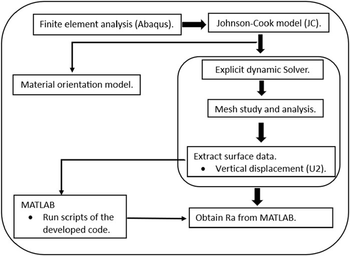
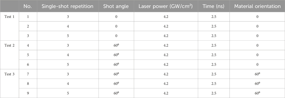
The finite element analysis approach was utilized in this study employing Abaqus CAE 2020 software with the explicit solver, as shown in Figure 1. In this study, nine sets of computational experiments were conducted with single-shot repetition, single-shot angles, laser power, time, and material orientation as parameters for the laser shock peening finite element modeling test, as shown in Table 1.
Fatigue failure of dental implants was previously observed, with the implant failing between the second and third threads. Based on the study by Lebea D. et al. (2024), the 60-degree angle was selected. However, by using laser shock peening, its lower surface roughness property can be increased. Their work has shown that a 60⁰ orientation offers potential for application as implant material. For the 60⁰ orientation sample, the study has created an avenue for exploration. In this study, we employ cutting-edge computational modeling approaches to improve the surface roughness qualities of titanium attributes. However, Fameso et al. (2021) reported the successful application of this technology in turbine usage.
2.1.2 Mesh study, boundary condition, loading condition, and orientation
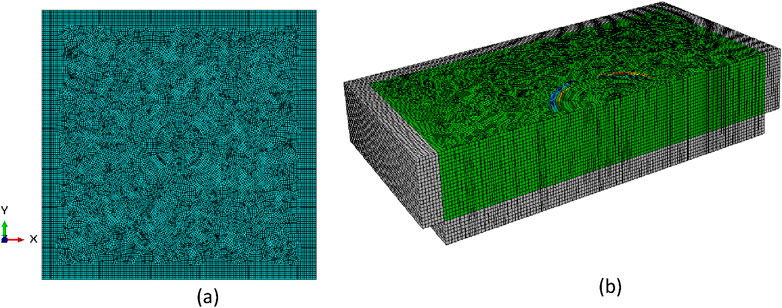
A total of 383313 nodes were used, and 359440 linear hexahedral elements of type C3D8R were employed, as seen in Figure 2A. The mesh convergence analysis was conducted to ascertain the mesh quality. The default mesh size was progressively decreased until the stress curve flattened, and a constant result was attained. Figure 2B shows infinite elements, with a total mesh size of 0.0001 mm. A finer mesh was used around the shot’s diameter to reduce distortion.
The study introduces fiber orientation, single repetition, and pressure load orientation. This follows a worst-case scenario in the application of dental implant design. By changing the orientation of the material, it is possible to enhance the strength and stiffness of the material. The fiber orientation was assigned to the model at a 60-degree angle using the coordinate system, as shown in Figure 3A.
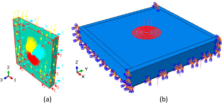
Figure 3. (A) Material orientation using the coordinate system at 60 degrees and (B) boundary conditions and applied surface load at 60 degrees.
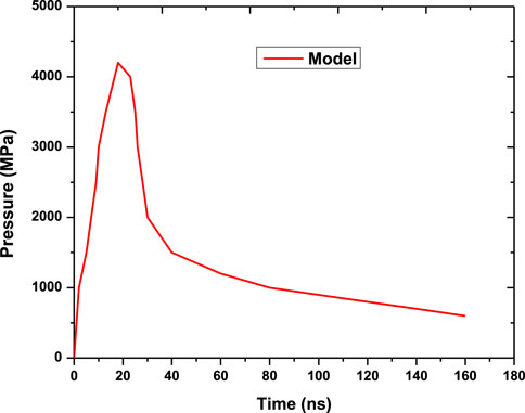
The boundary conditions of the samples are set to allow laser power to be applied as a distributed load along the laser shot spot, as shown in Figure 3B. The simulation follows the pulse temporal profile, as shown in Figure 4, and the load was assigned a 60-degree angle for computational tests 2 and 3. Computational test 1 had no material orientation or shot angles, as shown in Table 1. This approach allowed the comparison and distinction of the effect of the applied parameters.
2.2 Material model development
2.2.1 Johnson–Cook plasticity model
The relationships between stress and strain in the degradation of metallic materials may be sufficiently described using the Johnson–Cook model in the presence of large deformation, high strain rates, and increasing temperatures. Its simple structure and ease of estimating material constants have made it a popular tool among researchers to predict the flow behavior of various materials. The flow stress model has the following expression:
where σ is the equivalent stress and

Table 2. Representation of the Ti6Al4V Johnson–Cook material parameters as per Equation 1 (Zhang et al., 2015; Zhou et al., 2012).
2.2.2 Surface roughness
A novel surface roughness model is proposed that considers the laser shock peening process parameters to determine the optimum Ra for dental applications. The arithmetic mean of the absolute value of the measured actual contour offset within a sampling length is known as the contour arithmetic mean deviation, and it is chosen as the surface roughness evaluation parameter. Its computation formula is given as follows:
where
The contour centerline slope, denoted by
The surface roughness code was updated to develop a novel model, and the material orientation (
The period (T) and amplitude (A) parameters are used to introduce a repetitive pattern to the surface profile, and the passes parameter is used to simulate laser passes:
The laser power (w) parameter is used to simulate the effect of laser passes on the surface roughness. The pulse duration (ts) and the time between passes (tb) parameters are used to simulate the laser pulse duration and number of passes (
The final roughness value can be expressed as follows:
Equations 2–8 were coded using MATLAB 2023 with displacement coordinates as inputs to determine the surface roughness.
2.3 Experimental setup
To investigate the effect of surface roughness on titanium samples, the laser shock peening experiment was carried out. The adopted experimental methodology was successfully used in the previous studies (Guo et al., 2018; Luo et al., 2021; Warzanskyj et al., 2023; Zhou et al., 2012). The specimens with dimensions of 1.4 × 1.4 × 0.2 cm were cut from a titanium plate. One side of the specimens was peened with the ablative tape using the Nd: Glass process. For every shot, a peak laser power density, a 0.2-cm spot diameter, and a pulse width were used, as described in Table 1 .The output data for every shot were stored on a PC that was connected to the oscilloscope for later recollection. This was done to guarantee that the laser’s settings would not change during the three shots. A consistent water flow was maintained in each shot to maintain the same thickness of the water film. To maintain a consistent water film thickness for every shot, the water flow was kept constant. Mainly, diffraction techniques are used to detect residual stresses. To measure the compressive residual stress, X-ray diffraction (XRD) was performed. The cosα and sin2ψ methods, which may be utilized with synchrotron and neutron diffraction methods and laboratory diffractometers, are among the four primary diffraction methods commonly employed for measuring residual stresses (Schubnell et al., 2023).
3 Results and discussion
3.1 Computational model calibration
Experimental data were used to calibrate the computational model (Lan et al., 2020; Zhou et al., 2012). Figures 5, 6 show that the compressive residual stress was −592.18 MPa for the experimental sample and −578.45 MPa for the computational model when laser power was applied and repeated three times. The difference between the experimental and computational results as a consequence was 2.32%, as shown in Table 3. An acceptable value of less than 10% indicates that the computational and experimental results align closely.
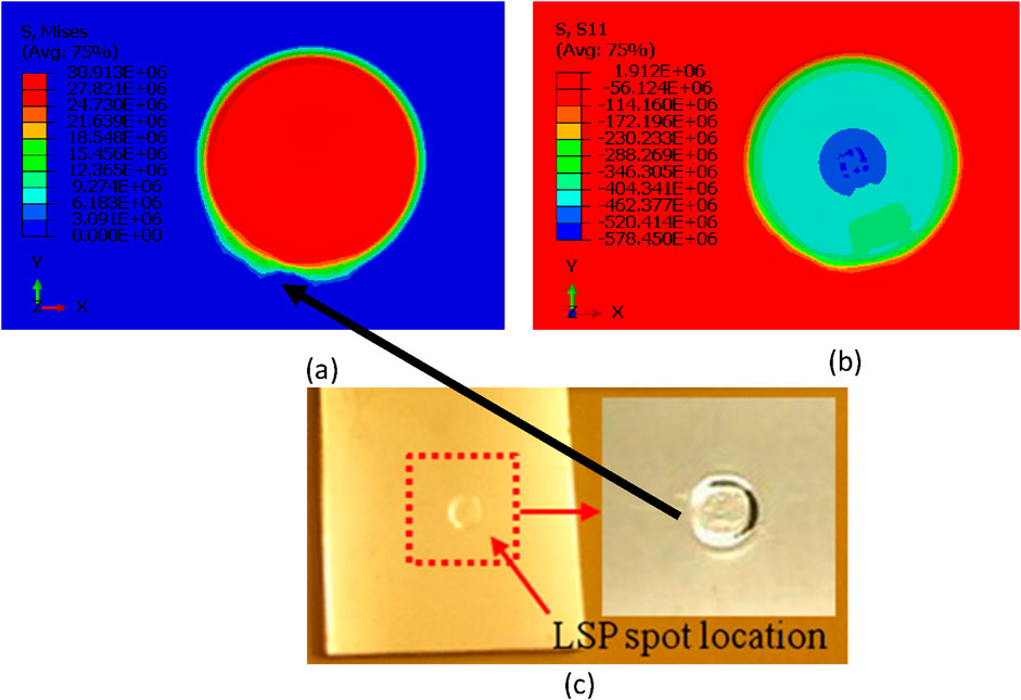
Figure 5. (A, B) Computational results of von Mises and residual stress and (C) deformed laser spot diameter.
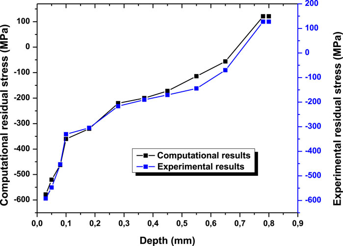
Figure 6. Compressive residual stress of Ti64 tested at 4.2 GW/cm2, and this test comprises both experimental and computational results.
The titanium sample that has been treated with LSP is depicted in Figure 5C. Although there is no discernible bending deformation in the sample, the distortion caused by the single spot shock is clearly visible. Figure 5 shows that when the samples are computed and experimented with laser shock, they display a similar imprint. The computational results of Zhou et al. (2012) reveal that the compressive residual stress of Ti6Al4V was 578 MPa. Furthermore, Nie et al. (2021) conducted an experimental study using 4.24 GW/cm2 laser power and reported that the compressive residual stress was 410 MPa. Ran et al. (2022) utilized a lap rate of 30% to treat titanium alloy and achieved a residual stress of up to 552.4 MPa without ablation. The results of the current study are favorably compared with a recently published review of various LSP processes in titanium materials (Jia et al., 2024). Experimental trials, which are costly and time-consuming, are typically used to investigate the impact of LSP factors on surface roughness. The impact of LSP parameters on residual stress and surface displacement in metallic components has recently been investigated using the FEA approach (Lan et al., 2020; Ran et al., 2018; Singh and Deoghare, 2023; Zhang et al., 2023).
3.2 Residual stress analysis
Based on the numerical model, parametric research was used to anticipate the influences of material orientation, number of shocks, and pulse energy on surface residual stress and von-Mises (Table 1). Using the finite element model (FEM), Li et al. (2015) computed the impact of LSP on the mechanical characteristics of titanium alloy blades. In the present investigation, JC served as the material model, and Figure 7 displays the results of the compressive residual stress.
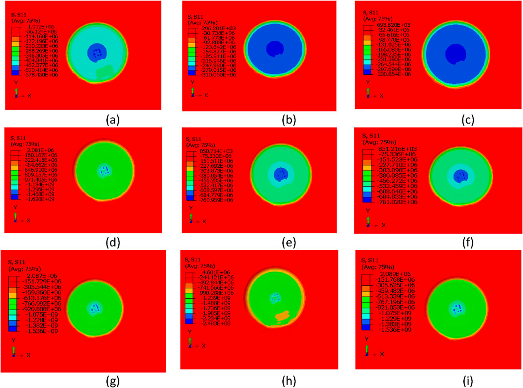
Figure 7. Surface residual stress: (A–C) without angle and material orientation, (D–F) with a load applied at 60 degrees and without material orientation, and (G–I) load applied at 60 degrees and material orientation assigned at 60 degrees.
The compressive residual stress of the examined samples, without an angle or material orientation, was determined to be −578.450 MPa after three repetitions, and it increased to −1.620 MPa after four repetitions. Conversely, the CRS for the five repetitions was measured to be −1.536 MPa (Figures 7A, D, G). Furthermore, the weight applied to the model was at a 60-degree angle, and the material orientation was not assigned (Figures 7B, E, H). The study found that a compressive residual stress of −31.050 MPa was detected after three repetitions and −760.959 MPa after four repetitions. The study also considers a material orientation of 60 degrees and a force applied at 60 degrees (Figures 7C, F, I). During the fourth repetition, the values increased from −330.85 MPa to −761.020 MPa. Moreover, −1.536 MPa was noted for five repetitions. Zhang et al. (2023) used ABAQUS/Explicit to conduct experimental and numerical research. The modeling results indicated that the compressive residual stress decreased, while the depth increased with radial inward movement. When compared to experimental data, the modeling results showed a good agreement in the residual stress distribution along the impact spot and the depth direction. When comparing the modeling results to the experimental data, there was a good agreement in the depth direction and the residual stress distribution along the impact spot.
3.3 Surface roughness analysis
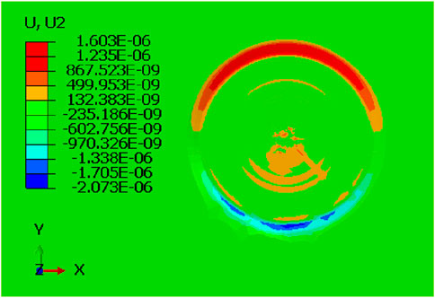
The vertical displacement values were retrieved from the computational output, and the surface roughness was computed using MATLAB, as described in Equation 4. Surface roughness (Ra) parameters were obtained using the provided code, which was developed using Equations 2–8. With three repetitions, no material orientation, no loading angle, and a laser power of 4.2 GW/cm2, Figure 8 displays the contour plot of the surface’s vertical displacements (U2).
Figures 9A–C depict the models’ vertical displacement. Based on material orientation, angle loading, and repetition, these data show that the applied laser power changes. An earlier investigation discovered that as the pulse energy increases, the surface indentation becomes more noticeable and vertical displacements increase (Ran et al., 2018). According to Shen et al. (2022), there is an alternative perspective that suggests LSP surface treatment serves as a filter, allowing LSP to identify high-viability cells while excluding unhealthy cells, which could potentially yield more advantages.
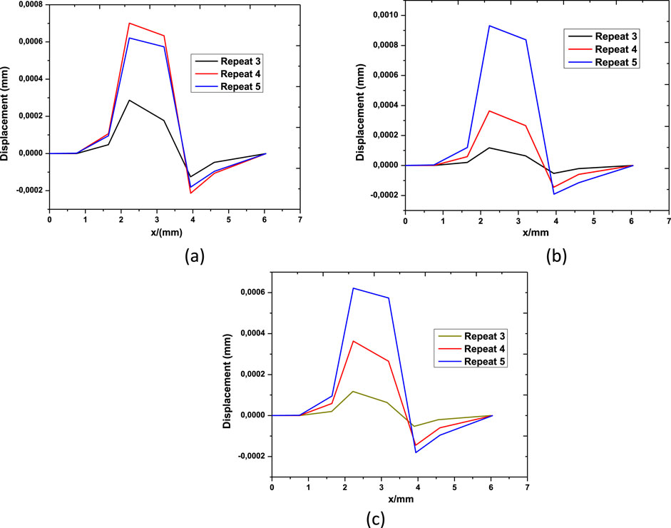
Figure 9. Vertical displacement profile: (A) without angle and material orientation, (B) with a load applied at 60 degrees and without material orientation, and (C) load applied at 60 degrees and material orientation assigned at 60 degrees.
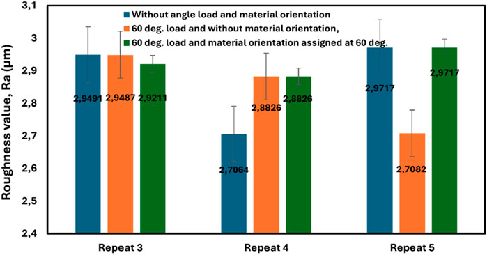
A bar graph (Figure 10) was then used to compare the acquired surface plot results. When considering three repetitions, the model without an angle and material orientation recorded a surface roughness value of 2.9491 µm; when a loading angle of 60 degrees was included, the surface roughness increased to 2.9487 µm. Additionally, when the loading angle and material orientation were applied, the surface roughness was reported to be 2.9211 µm. When material orientation and loading were applied, the model yielded a lower Ra value of 2.7064 µm after increasing the repetition to four times. These findings reveal that Ra values can be increased through four repetitions with changes in loading angle and material orientation. After evaluating five repetitions, the current investigation established that the Ra value was 2.9717 for models without angle load and material orientation. Furthermore, it decreased to 2.7082 when 60-degree loading angle was applied without considering material orientation. Under the conditions of a 60-degree loading angle and corresponding material orientation, Ra values were again found to be 2.9717 µm. The results compared favorably with previously published experimental findings (Luo et al., 2021; YIN et al., 2019). Significant variations were observed between the smooth (Ra 0.23 ± 0.02 µm) and rough (Ra 1.98 ± 0.12 µm) surfaces, as determined by the roughness analysis conducted via interferometry. The in vitro study was conducted to investigate the impact of surface treatment on bone cell proliferation and differentiation. The results showed that the untreated surface had a Ra value of 0.3 ± 01 μm, while the treated surface had a maximum Ra value of 1.4 ± 0.04 µm (Stoilov et al., 2022). Since it is predicted that surfaces with Ra values of 3–5 μm will be more favorable for osteoblast responses than smooth surfaces with Ra values <1 μm, the majority of studies (Flack, Schultz, and Volino, 2020; Lebea L. et al., 2023; Zarei et al., 2020) now focus more on lower roughness values of <5 μm. Understanding the circumstances of Ti-64, ELI can be accomplished in part by using surface roughness characterization, a crucial analytical technique (Hazzan and Pacella, 2022). The in vitro investigations conducted by Zhao et al. (2006) revealed a complex surface topography consisting of 1–3 μm submicron pits superimposed atop 30 μm diameter hemispherical micro-craters (Zhao et al., 2006). The hybrid structure was shown to produce the most developed osteoblast phenotype. Consistent with the in vivo experiment results, studies conducted by Tamayo et al. (2021) and Wang et al. (2023) similarly revealed no deleterious effects of the rough SLM Ti implants on bone repair.
4 Conclusion
In this paper, the computational model of laser shock peening is examined with five parameters, namely, single-shot angle, single-shot repetition, duration, material orientation, and laser power. For the first time, such studies are carried out to evaluate the surface roughness model for dental implant applications. After applying laser power and performing three repetitions, the compressive residual stress measured was −592.18 MPa for the experimental sample and −578.45 MPa for the computational model, resulting in a discrepancy of 2.32% between the computational and experimental results. The compressive residual stress of the examined samples, without considering angle or material orientation, was determined to be −578.450 MPa after three repetitions, and it decreased to −1.620 MPa after four repetitions. These findings demonstrate that Ra values can be increased through four repetitions while adjusting the material orientation and loading angle. After evaluating five repetitions, the current investigation determined the ideal Ra values to be 2.9717, 2.7082, and 2.9717 µm.
Data availability statement
The raw data supporting the conclusions of this article will be made available by the authors, without undue reservation.
Author contributions
LL: writing–original draft and writing–review and editing. DD: supervision and writing–review and editing. HN: supervision and writing–review and editing. FN: supervision and writing–review and editing.
Funding
The author(s) declare that financial support was received for the research, authorship, and/or publication of this article. The research was supported and funded by Tshwane University of Technology, Central University of Technology, and University of South Africa (UNISA) research funding.
Acknowledgments
The author carried out the computational modeling at the Bloemfontein campus of the Central University of Technology.
Conflict of interest
The authors declare that the research was conducted in the absence of any commercial or financial relationships that could be construed as a potential conflict of interest.
Publisher’s note
All claims expressed in this article are solely those of the authors and do not necessarily represent those of their affiliated organizations, or those of the publisher, the editors, and the reviewers. Any product that may be evaluated in this article, or claim that may be made by its manufacturer, is not guaranteed or endorsed by the publisher.
References
Al-zubaidi, S. M., Madfa, A. A., Mufadhal, A. A., Hameed, O. S., Yue, X.-G., and Yue, X. G. (2020). Improvements in clinical durability from functional biomimetic metallic dental implants. Front. Mater. 7. doi:10.3389/fmats.2020.00106
Attolico, M. A., Barile, C., Casavola, C., Moramarco, V., Furfari, D., and Busse, D. O. (2022). Effects of laser shock peening on surface roughness and residual stress of AA 7050-t7451. J. Mater. Eng. Perform. 31 (10), 7973–7988. doi:10.1007/s11665-022-06857-7
Cheng, G. J. (2013). Shock induced plastic deformation: the case of copper. J. Manuf. Sci. Eng. 132, 1–8. doi:10.1115/1.4002849
Crupi, V., Kara, E., Epasto, G., Guglielmino, E., and Aykul, H. (2017). Static behavior of lattice structures produced via direct metal laser sintering technology. Mater. Des. 135, 246–256. doi:10.1016/j.matdes.2017.09.003
Fameso, F., Desai, D., Kok, S., Newby, M., Glaser, D., and Fameso, F. (2021). Coupled explicit-damping simulation of laser shock peening on X12Cr steam turbine blades. J. Phys. Conf. Ser. 1780 (1), 012002. doi:10.1088/1742-6596/1780/1/012002
Flack, K. A., Schultz, M. P., and Volino, R. J. (2020). The effect of a systematic change in surface roughness skewness on turbulence and drag. Int. J. Heat Fluid Flow 85, 108669. doi:10.1016/j.ijheatfluidflow.2020.108669
Galati, M., Minetola, P., and Rizza, G. (2019). Surface roughness characterisation and analysis of the electron beam melting (EBM) process. Materials 12 (13), 2211. doi:10.3390/ma12132211
Guo, W., Sun, R., Song, B., Zhu, Y., Li, F., Che, Z., et al. (2018). Laser shock peening of laser additive manufactured Ti6Al4V titanium alloy. Surf. Coatings Technol. 349, 503–510. doi:10.1016/j.surfcoat.2018.06.020
Hazzan, K. E., and Pacella, M. (2022). Surface defect detection and prediction in carbide cutting tools treated by lasers. Procedia CIRP 108 (C), 851–856. doi:10.1016/j.procir.2022.05.198
Jemat, A., Ghazali, M. J., Razali, M., and Otsuka, Y. (2015). Surface modifications and their effects on titanium dental implants. BioMed Res. Int. 2015, 1–11. doi:10.1155/2015/791725
Jia, M., Wang, Y., Yue, J., Cao, C., Li, K., Yu, Yu, et al. (2024). Recent progress in laser shock peening: mechanism, laser systems and development prospects. Surfaces Interfaces 44, 103757. doi:10.1016/j.surfin.2023.103757
Khamis, N. A., Zin, S.Md, and Bahari, A. R. (2016). Mild steel sheet metal forming using Abaqus software: influence of drawbeads in minimize springback. ARPN J. Eng. Appl. Sci. 11 (20), 11888–11893.
Kunrath, M. F. (2020). Customized dental implants: manufacturing processes, topography, osseointegration and future perspectives of 3D fabricated implants. Bioprinting 20, e00107. doi:10.1016/j.bprint.2020.e00107
Lan, L., Xin, R., Jin, X., Gao, S., He, Bo, Rong, Y., et al. (2020). “Effects of laser shock peening on microstructure and properties of Ti–6Al–4V titanium alloy fabricated via selective laser melting.” Materials 13:3261. doi:10.3390/ma13153261
Lebea, L., Desai, D., Ngwangwa, H., and Nemavhola, F. (2024). Evaluation of 3D printing orientation on volume parameters and mechanical properties of as-build TI64ELI. Metals 14 (4), 1–15. doi:10.3390/met14040447
Lebea, L., Ngwangwa, H. M., Desai, D. A., and Nemavhola, F. (2022) “Corrosion resistance of 3D-printed titanium alloy Ti64-ELI parts for dental application,” in Applied Bionics and biomechanics 2022, 1–8.
Lebea, L., Ngwangwa, H. M., Desai, D., and Nemavhola, F. (2021). Experimental investigation into the effect of surface roughness and mechanical properties of 3D-printed titanium Ti-64 ELI after heat treatment. Int. J. Mech. Mater. Eng. 16, 16. doi:10.1186/s40712-021-00138-2
Lebea, L., Ngwangwa, H. M., and Subramaniyan, K. A. (2023). “Role of sensing integrated prosthetic socket in comfort,” in Digital design and manufacturing of medical devices and systems. Editors R. Velu, K. Subburaj, and A. K. Subramaniyan (Singapore: Springer Nature Singapore), 77–92.
Lebea, L., Ngwangwa, H. M., Desai, D., and Nemavhola, F. (2022). “Investigation on 3D printed dental titanium Ti64ELI and lifetime prediction,” in Eighth international conference on structural engineering, mechanics and computation (SEMC 2022, cape town, South Africa, 5-7 september 2022) (United Kingdom: CRC Press. Taylor & Francis), 613–617.
Le Guéhennec, L., Soueidan, A., Layrolle, P., and Amouriq, Y. (2007). Surface treatments of titanium dental implants for rapid osseointegration. Dent. Mater. 23 (7), 844–854. doi:10.1016/j.dental.2006.06.025
Li, P., Huang, S., Xu, H., Li, Y., Hou, X., Wang, Q., et al. (2015). Numerical simulation and experiments of titanium alloy engine blades based on laser shock processing. Aerosp. Sci. Technol. 40, 164–170. doi:10.1016/j.ast.2014.10.017
Luo, X., Ning, D., and Wang, X. (2021). The effect of laser shock peening, shot peening and their combination on the microstructure and fatigues properties of Ti-6Al. Int. J. Fatigue 1 (153), 153. doi:10.1007/978-1-4419-9863-7_1423
Marenzi, G., Impero, F., Scherillo, F., Sammartino, J. C., Squillace, A., and Spagnuolo, G. (2019). Effect of different surface treatments on titanium dental implant micro-morphology. Materials 12 (5), 733. doi:10.3390/ma12050733
Nie, X., Tang, Y., Zhao, F., Yan, Li, Wu, H., Chen, W., et al. (2021). Formation mechanism and control method of residual stress profile by laser shock peening in thin titanium alloy component. Materials 14 (8), 1878. doi:10.3390/ma14081878
Ningthemba, S., and Singh, A. (2022). Laser shock peening of laser based directed energy deposition and powder bed fusion additively manufactured parts: a review. Metals Mater. Int. 29, 1563–1585. doi:10.1007/s12540-022-01334-1
Obiukwu, O., Martin, N., Okafor, B., Lawa, G., Grem, L., Obiukwu, O., et al. (2015). The effect of surface finish on the low cycle fatigue of low and medium carbon steel. Int. Conf. Mech Ind. Engg (August).
Öztürk, B., and Kara, F. (2020). Calculation and estimation of surface roughness and energy consumption in milling of 6061 alloy. Adv. Mater. Sci. Eng. doi:10.1155/2020/5687951
Ran, Z., Xie, D., Zhu, S., and Zhang, Y. (2022). Effect of high frequency Nd: YLF flat-top laser shock on surface stress and micro-deformation of titanium alloy. Met 47 (03), 204–210.
Ran, Z., Zhang, Y., Sun, G., Shen, X., and Pu, Li (2018). Finite element analysis of surface roughness generated by multiple laser shock peening. Rare Metal Mater. Eng. 47 (1), 33–38. doi:10.1016/S1875-5372(18)30067-5
Ren, B., Yi, W., Liu, C., Wang, H., Yu, M., Zhang, X., et al. (2021). Improved osseointegration of 3D printed Ti-6Al-4V implant with a hierarchical micro/nano surface topography: an in vitro and in vivo study. Mater. Sci. Eng. C 118, 111505. doi:10.1016/j.msec.2020.111505
Rozmus-Gornikowska, M., Kusin´ski, J., and Cieniek, Ł. (2020). Effect of laser shock peening on the microstructure and properties of the inconel 625 surface layer. J. Mater. Eng. Perform. 29, 1544–1549. doi:10.1007/s11665-020-04667-3
Ruiz de Galarreta, S., Jeffers, J. R. T., and Ghouse, S. (2020). A validated finite element analysis procedure for porous structures. Mater. Des. 189, 108546. doi:10.1016/j.matdes.2020.108546
Schubnell, J., Carl, E.-regine, Sarmast, A., Hinterstein, M., Preußner, J., Seifert, M., et al. (2023). Surface conditions after LASER shock peening of steel and aluminum alloys using ultrafast laser pulses. Materials 16, 6769–6813. doi:10.3390/ma16206769
Shen, X., Shukla, P., Nayak, S., Gopal, V., Subramanian, P., Benjamin, A. S., et al. (2022). Biological and mechanical response of laser shock peening orthopaedic titanium alloy (Ti-6Al-7Nb). Proc. Institution Mech. Eng. Part H J. Eng. Med. 236 (8), 1169–1187. doi:10.1177/09544119221105849
Singh, S. N., and Deoghare, A. B. (2023). Laser shock peening of laser based directed energy deposition and powder bed fusion additively manufactured parts: a review. Metals Mater. Int. 29, 1563–1585. doi:10.1007/s12540-022-01334-1
Stoilov, M., Stoilov, L., Enkling, N., Stark, H., Winter, J., Marder, M., et al. (2022). Effects of different titanium surface treatments on adhesion, proliferation and differentiation of bone cells: an in vitro study. J. Funct. Biomaterials 13 (3), 143. doi:10.3390/jfb13030143
Suh, A. Y., Polycarpou, A. A., and Thomas, F. C. (2003). Detailed surface roughness characterization of engineering surfaces undergoing tribological testing leading to scuffing. Wear 255 (1–6), 556–568. doi:10.1016/s0043-1648(03)00224-2
Sun, J., Li, J., Chen, X., Xu, Z., Lin, Y., Jiang, Q., et al. (2023). Optimizing parameters with FEM model for 20CrMnTi laser shocking. Materials 16 (328), 328–412. doi:10.3390/ma16010328
Tamayo, J. A., Riascos, M., Vargas, C. A., and Baena, L. M. (2021). Additive manufacturing of Ti6Al4V alloy via electron beam melting for the development of implants for the biomedical industry. Heliyon 7 (5), e06892. doi:10.1016/j.heliyon.2021.e06892
Wang, C., Wu, J., Liu, L., Xu, D., Liu, Y., Li, S., et al. (2023). Improving osteoinduction and osteogenesis of Ti6Al4V alloy porous scaffold by regulating the pore structure. Front. Chem. 11 1190630–1190715. doi:10.3389/fchem.2023.1190630
Warzanskyj, W., Angulo, I., Cordovilla, F., Díaz, M., Porro, J. A., García-Beltrán, A., et al. (2023). Analysis of the thermal stability of residual stresses induced in Ti-6Al-4 V by high density LSP treatments. J. Alloys Compd. 931, 167530. doi:10.1016/j.jallcom.2022.167530
Xiao, W. L., Chen, H. B., and Yin, Y. (2012). Effects of surface roughness on the fatigue life of alloy steel. Key Eng. Mater., 525–526.
Xu, Y., Zhang, D., Hu, S., Chen, R., Gu, Y., Kong, X., et al. (2019). Mechanical properties tailoring of topology optimized and selective laser melting fabricated Ti6Al4V lattice structure. J. Mech. Behav. Biomed. Mater. 99, 225–239. doi:10.1016/j.jmbbm.2019.06.021
Yin, M. gui, bing Cai, Z., Zhen yang, L. I., Zhong, rong ZHOU, Wang, W. jian, and Wei feng, H. E. (2019). Improving impact wear resistance of Ti-6Al-4V alloy treated by laser shock peening. Trans. Nonferrous Metals Soc. China English Ed. 29 (7), 1439–1448. doi:10.1016/S1003-6326(19)65051-X
Zarei, H., Marulli, M. R., Paggi, M., Pietrogrande, R., Üffing, C., and Weißgraeber, P. (2020). Adherend surface roughness effect on the mechanical response of silicone-based adhesive joints. Eng. Fract. Mech. 240 107353. doi:10.1016/j.engfracmech.2020.107353
Zhang, X., Li, H., Duan, S., Yu, X., Feng, J., Wang, B., et al. (2015). Modeling of residual stress field induced in Ti-6Al-4V alloy plate by two sided laser shock processing. Surf. Coatings Technol. 280, 163–173. doi:10.1016/j.surfcoat.2015.09.004
Zhang, Z., Qiu, W., Zhang, G., Liu, D., and Wang, P. (2023). Progress in applications of shockwave induced by short pulsed laser on surface processing. Opt. Laser Technol. 157 108760. doi:10.1016/j.optlastec.2022.108760
Zhao, Ge, Zinger, O., Schwartz, Z., Wieland, M., Landolt, D., and Boyan, B. D. (2006). Osteoblast-like cells are sensitive to submicron-scale surface structure. Clin. Oral Impl. Res. 258–64 17, 258–264. doi:10.1111/j.1600-0501.2005.01195.x
Keywords: laser shock peening, residual stress, computational modeling, loading angle, material orientation
Citation: Lebea L, Desai D, Ngwangwa H and Nemavhola F (2024) Influence of material orientation, loading angle, and single-shot repetition of laser shock peening on surface roughness properties. Front. Manuf. Technol. 4:1421589. doi: 10.3389/fmtec.2024.1421589
Received: 22 April 2024; Accepted: 30 October 2024;
Published: 15 November 2024.
Edited by:
Reza Teimouri, Cracow University of Technology, PolandReviewed by:
Pasquale Guglielmi, Politecnico di Bari, ItalyJinoop Arackal Narayanan, Teesside University, United Kingdom
Copyright © 2024 Lebea, Desai, Ngwangwa and Nemavhola. This is an open-access article distributed under the terms of the Creative Commons Attribution License (CC BY). The use, distribution or reproduction in other forums is permitted, provided the original author(s) and the copyright owner(s) are credited and that the original publication in this journal is cited, in accordance with accepted academic practice. No use, distribution or reproduction is permitted which does not comply with these terms.
*Correspondence: Lebogang Lebea, bGxlYmVhQGN1dC5hYy56YQ==
 Lebogang Lebea
 Dawood Desai
 Harry Ngwangwa
 Fulufhelo Nemavhola4